
Pressure sensor mat calibration should set activation and release thresholds from measured empty and required-occupied distributions in the finished mechanical stack. For OEM seat teams, the decision is not a universal force value: it is whether the worst credible empty condition and the weakest required occupied condition remain separated after preload, temperature, position, assembly variation, and measurement uncertainty are included.
JASPER certifications: ISO 9001, ISO 13485, IATF 16949, and ISO 14001.
A seat occupancy sensor mat can provide a contact state, an analog signal, several zone signals, or a conditioned output. That architecture changes the calibration method. This guide develops a defensible pressure mat threshold and seat sensor hysteresis rule without inventing a trigger load. Vehicle-level occupant classification, diagnostics, and regulatory approval remain outside a component supplier's calibration decision.
Define the Decision Before Choosing a Threshold
A calibration plan begins with states, not numbers. State what must count as empty, what must count as occupied, which transitional conditions may hold the previous state, and which electrical faults require a separate diagnostic state. Also identify the more serious error for the application: false activation, missed activation, delayed release, or repeated state changes.
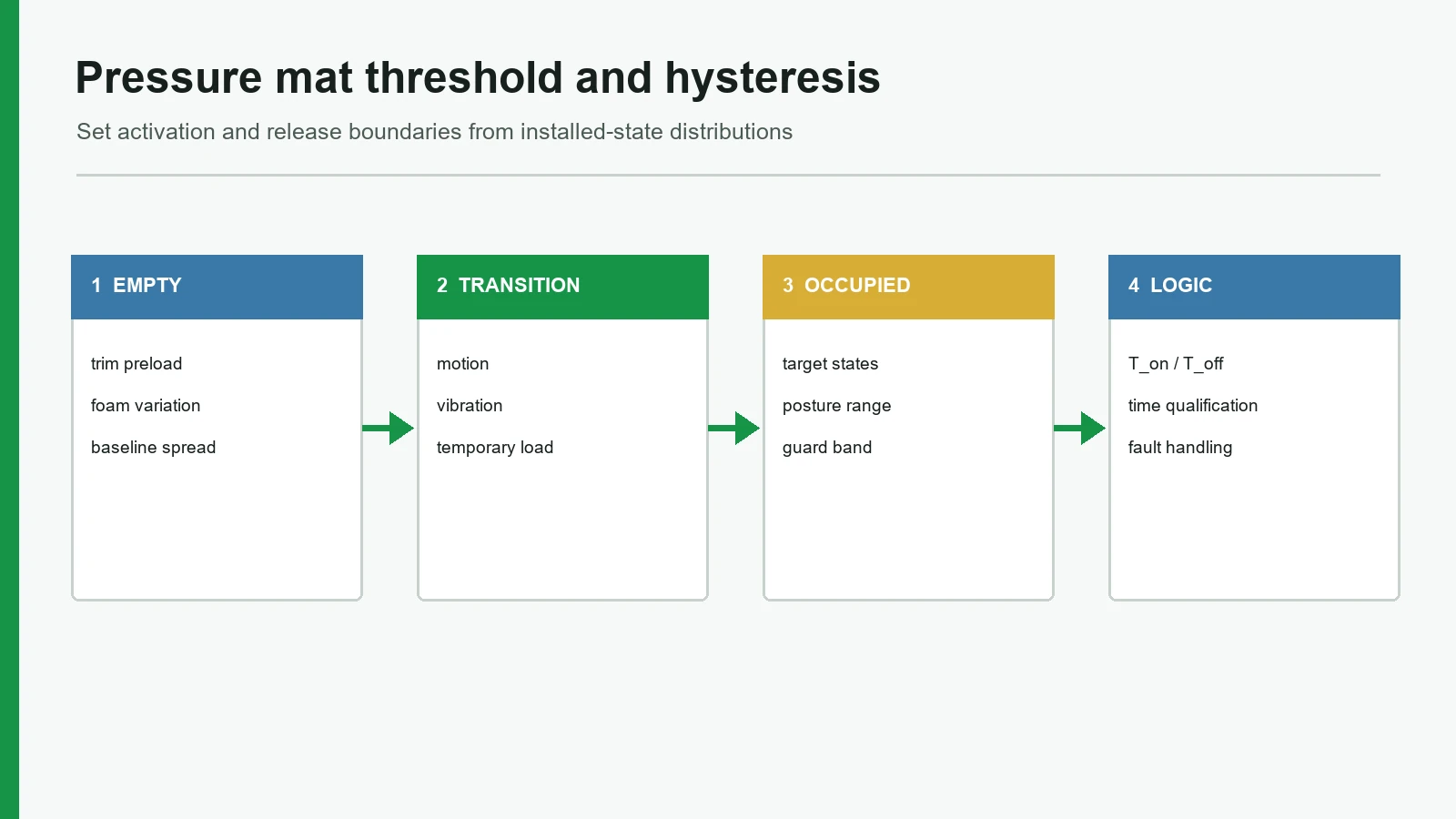
Six terms keep the decision precise:
| Term | Engineering meaning | What it does not prove |
|---|---|---|
| Baseline | Output of the complete assembly in its defined empty condition | The loose mat's bench output does not establish the installed baseline |
| Preload | Force already applied by trim, foam, adhesive, clips, support geometry, cable routing, or assembly compression | Preload is not the intended occupant load |
| Activation threshold, T_on | Boundary that must be crossed to change from empty to occupied | It does not define release behavior |
| Release threshold, T_off | Separate boundary that must be crossed to return from occupied to empty | It is not automatically the inverse of T_on |
| Hysteresis | Amplitude gap between activation and release boundaries | It does not qualify how long a condition persists |
| Debounce / time qualification | Required duration or sample count before a candidate state is accepted | It cannot separate two stable conditions that generate the same signal |
| Guard band | Deliberate margin between measured evidence and a decision boundary | It is not a universal percentage |
Texas Instruments' SNOA997A comparator note uses separate upper and lower trip points to keep a slowly changing or noisy input from toggling at one boundary. The same decision principle applies in software even when the mat does not contain a hardware comparator. The actual threshold values must still come from the installed sensor system.
NIST treats short-term repeatability, longer-term reproducibility or variability, calibration, stability, bias, and uncertainty as distinct parts of measurement-process characterization. One clean trace therefore demonstrates only one run. It does not establish a production boundary.
Pressure Sensor Mat Calibration Starts With the Installed Stack
The mat is one element in a load path. Seat trim can tension the foam; foam can spread or concentrate load; a support rib can create a local preload; an adhesive can change compliance; and a cable route can lift one edge. SAE paper 2005-01-0461 identifies seat-foam stiffness, trim preload, occupant or restraint condition, position, and temperature among the factors considered when laying out an automotive occupant-classification sensor mat.
A useful stack sketch looks like this:
Applied load / occupant condition
Upholstery or trim · ← tension can add preload
Cushion foam / load spreader · ← distributes force; changes with condition
Sensor mat and sensing zones · ← contact or analog response
Adhesive / carrier / protective film · ← changes local compliance
Seat pan, frame, ribs, or support · ← can create concentrated reaction loads
Cable + connector + interface circuit + controller state logic
A commercial pressure-mapping supplier, Tekscan, recommends calibrating its systems with the interface materials used in the application. That advice concerns Tekscan equipment rather than every occupancy mat, but the underlying test-design lesson is sound: a fixture that removes the production interface can remove the very preload and load distribution being evaluated.
Identify the output before planning occupant sensor calibration
“Pressure sensor mat” does not name one electrical behavior. The threshold can live in the mechanics, electronics, firmware, or all three.
| Output architecture | Observable output | Main calibration question | Typical mistake |
|---|---|---|---|
| Contact-type membrane mat | Open/closed continuity or contact resistance state | At what installed load condition does contact close, remain stable, and release? | Treating the device as a calibrated force instrument |
| Analog resistive mat | Resistance, conductance, voltage, or ADC count | Do empty and required-occupied signal distributions stay separated? | Assigning a threshold from one bare-sensor curve |
| Multi-zone mat | Several contact or analog channels | What per-zone evidence and combined logic define the state? | Validating only the center zone |
| Conditioned sensor module | Processed analog, digital state, or communication message | Which calibration resides inside the module, and what must the system controller verify? | Testing the message while ignoring physical load-path variation |
| Quantitative pressure map | Cell-by-cell pressure distribution | Is each cell/system calibrated for the measurement range and interface? | Assuming a pressure map and a binary occupancy switch have the same acceptance criteria |
Interlink Electronics publishes repeatability, hysteresis, and drift characteristics for its FSR 400 Series under stated product-specific conditions. Those values are useful evidence that resistive sensing error terms exist; they are not valid JASPER mat specifications and should not be copied into a seat requirement.
Build the Pressure Mat Threshold From Distributions
Assume the measured signal rises with load. Define:
- N_high: highest credible empty-state signal across the approved test space;
- O_low: lowest credible signal for a condition that must register as occupied;
- T_on: boundary for changing from empty to occupied; and
- T_off: boundary for changing from occupied to empty.
A clean steady-state relationship is:
N_high < T_off < T_on < O_low
For a signal that falls with load, reverse the inequalities and state logic. This relationship is not an industry threshold or a statistical confidence claim. It is the logical order required if two steady-state populations are to be separated by distinct release and activation boundaries.
Measure loading and unloading. A sensor, foam stack, or mechanical contact may follow a different path as load rises than it does as load falls. The open-access study Evaluating the Dynamic Performance of Interfacial Pressure Sensors at a Simulated Body-Device Interface evaluates calibration method, loading area, hysteresis, and repeatability as separate performance influences. Although the study concerns interface-pressure measurement rather than a binary automotive switch, it supports testing the real loading path rather than one static point.
Decide what the data permits
| Observed evidence | Threshold decision | Engineering action |
|---|---|---|
| N_high remains below O_low with usable margin in every required condition | A two-threshold rule may be feasible | Select T_off and T_on inside the evidence gap, then verify timing and faults |
| Empty and occupied bands are separated in nominal tests but approach each other under one variation | The decision is marginal | Add samples and repeats; examine that variation; improve mechanics or narrow the validated condition before approval |
| O_low <= N_high in a required condition | No single steady-state threshold can classify every measured case | Stop threshold approval; change zone geometry, stack, sensing architecture, or classification requirement |
| The bands separate, but brief transitions cross both thresholds | Amplitude separation exists but temporal disturbances remain | Add evidence-based time qualification after defining allowed response delay |
| Contact state is stable, but an accurate force value is requested | Binary detection may be feasible; force measurement is not proven | Use an architecture and calibration chain intended for quantitative force measurement |
Do not place a threshold directly on the worst observed point without an uncertainty argument. NIST's conformity-assessment work describes decision rules, acceptance zones, risk analysis, and guard bands as ways to account for measurement uncertainty. The size of a seat-sensor guard band depends on the measurement process, distribution evidence, consequences of an incorrect state, and controlled operating range. No public source supports one universal percentage.
Averages are especially weak threshold evidence. Two populations can have widely separated means yet overlap at their tails. Record sample identity, minimum, maximum, distribution shape, load position, loading direction, dwell, environment, electronics revision, and any excluded observation with a reason.
Seat Sensor Hysteresis and Debounce Solve Different Problems
Seat sensor hysteresis is an amplitude rule. Debounce is a time rule. Combining the terms hides two separate design decisions.
A two-boundary state machine can be written without choosing invented values:
When state = EMPTY:
accept OCCUPIED only if the signal crosses T_on
in the valid direction and remains qualified for the approved activation time
When state = OCCUPIED:
accept EMPTY only if the signal crosses T_off
in the release direction and remains qualified for the approved release time
Between T_off and T_on:
hold the current state
Microchip's sensor documentation likewise distinguishes a detection threshold from a hysteresis-adjusted release condition. It is not seat-specific guidance, but it illustrates why returning through a lower boundary prevents repeated toggling near the activation level.
Too little time qualification can pass contact bounce, vibration, occupant movement, or a short electrical disturbance. Too much can delay a required state change and mask an intermittent signal. Activation and release times may differ; both belong in the system requirement and must be checked against recorded transitions.
Most important, longer debounce cannot repair overlapping stable populations. If an empty condition and a required occupied condition settle at the same signal, both will eventually satisfy the same time rule.
A Nine-Point Calibration Framework
The following framework turns sensor data into an auditable decision. Each criterion has a acceptance evidence and a release blocker because a polished graph can still hide a weak method.
1. Define states and error consequences
Write separate requirements for empty, required occupied, transitional, hold, and electrical-fault conditions. Name the conditions that must be distinguished and the permitted response time for each direction.
The specification links each physical input to an expected state, timing requirement, and prohibited failure.
The project begins with “switch at X newtons” but has no definition for object loads, edge loads, transitions, or faults.
2. Identify architecture, signal direction, and interface
Document whether the output is contact, analog, multi-zone, or conditioned. For analog designs, identify whether the signal rises or falls with load, the supply/reference path, conversion method, sample rate, and filtering. For contacts, document pull-up or pull-down logic and fault interpretation.
A reviewer can trace the physical load to the controller variable and state transition.
Threshold equations are copied into firmware before anyone confirms signal polarity or circuit revision.
3. Freeze the representative mechanical stack
Control the mat revision, sensing-zone geometry, location, foam, trim tension, adhesive, carrier, support, cable route, connector, and fixture. Record any build that differs from the intended production stack.
Calibration samples represent the approved drawing and installation, including expected tolerance conditions.
The loose mat passes while the trimmed seat has a shifted empty baseline.
4. Measure populations rather than one sample
Collect repeated empty, transition, and required-occupied data from multiple representative assemblies. Include loading and unloading, relevant positions, reinstallation where installation variation matters, and the conditions needed to expose longer-term variation.
Raw observations retain sample and condition identity, allowing N_high and O_low to be traced.
Only an average curve or a single “golden sample” screenshot survives.
5. Establish activation and release boundaries
Plot empty and occupied populations before selecting values. Place T_on and T_off in the supported separation region and document signal direction, rationale, and margin. A threshold pair is initial until the full validation matrix passes.
Both boundaries have a written link to measured distributions and wrong-decision risk.
One boundary controls activation and release despite slow transitions or noise.
6. Set time qualification independently
Measure transition duration, contact bounce, vibration response, occupant movement, and any controller filtering. Choose activation and release time rules that reject prohibited disturbances without violating the system response requirement.
Timing is verified with recorded signals and exact controller logic.
Debounce keeps increasing until a noisy demonstration appears stable.
7. Challenge operating and assembly variation
Risk-screen temperature, conditioning, foam/trim tolerance, mat and spacer variation, adhesive thickness, support geometry, supply/reference variation, harness resistance, load position, dwell, and repeated loading. Not every project needs the same test matrix; every omitted factor needs a reason.
The matrix links each factor to a plausible baseline, span, timing, or fault effect.
Approval uses room-temperature center loading on one freshly assembled seat.
8. Validate state logic and diagnostic behavior
Run the exact state machine against recorded signals and production-representative hardware. Test startup, power cycle, open circuit, short circuit, disconnected zone, contradictory zone states, delayed activation, delayed release, and chatter where those conditions apply.
Physical condition, raw signal, filtered signal, state, and diagnostic result are synchronized in the test record.
A sensor plot passes, but no one exercises the shipping firmware or controller.
9. Control acceptance and future changes
Define which characteristics receive development validation, first-article approval, and production screening. List changes that trigger review: mat revision, zone layout, foam, trim, adhesive, support, installation, connector, interface circuit, filtering, sample rate, or state logic.
Threshold values, test method, fixtures, software revision, acceptance rule, and revalidation triggers are controlled records.
The only record is a firmware constant or an uncontrolled spreadsheet.
Run Occupant Sensor Calibration as a Six-Step Workflow
Step 1 — Write the classification and response requirement
Create a table of physical conditions and expected outcomes. Separate presence detection from weight measurement or regulated occupant classification. If the project interfaces with an airbag or another safety function, the OEM or system integrator must define the vehicle-level requirement.
Step 2 — Build and document representative samples
Use the intended stack and record every revision. Photograph or draw the mat location, sensing zones, foam interfaces, trim, supports, cable, and fixture. Keep sample identity through the entire study.
Step 3 — Acquire empty, transition, and occupied distributions
Measure all required positions in both loading directions. Include dwell and recovery. Save raw values rather than only pass/fail states. If the system is multi-zone, retain each channel before calculating a combined decision.
Step 4 — Propose thresholds, hysteresis, and timing
Apply the correct signal direction. Reject the proposal if the populations overlap. If separation exists, choose initial T_on and T_off boundaries, then derive time qualification from transition data and allowed response delay.
Step 5 — Validate the complete decision chain
Test the final stack, electronics, filtering, firmware, diagnostics, and operating variations together. JASPER's testing and validation capabilities page can support a project-specific component test plan, but the OEM or seat-system owner must approve system acceptance and vehicle validation.
Step 6 — Release production checks and change triggers
A production screen does not need to repeat every development condition. It must, however, protect the critical characteristics that preserve the approved margin. Define the fixture, applied condition, response window, traceability, retest rule, and reaction plan before release.
Use a Test Matrix That Exposes Margin Loss
The matrix should be proportional to application risk. It is a planning structure, not a universal sample-count prescription.
| Factor | Conditions to compare | Evidence to retain | Margin-loss question |
|---|---|---|---|
| Assembly | Representative mats, cushions, trim builds, and reinstallations | Sample and build identity; raw baseline and loaded signal | Does part/build variation move N_high or O_low? |
| Position | Center, edge, zone boundary, specified occupant/object positions | Location, footprint, orientation, state result | Is a required condition weak at a zone edge? |
| Direction | Loading and unloading | Activation/release signal and time | Is mechanical hysteresis larger than expected? |
| Dwell and recovery | Immediate, approved dwell, and post-unload recovery | Time-series raw and filtered signals | Does creep or delayed recovery consume margin? |
| Environment | Required temperature/conditioning states | Stabilization method, condition, signal distribution | Does baseline or span shift outside the lab state? |
| Electronics | Supply/reference, interface tolerances, harness/connector states | Electrical configuration and controller variable | Does the same physical condition produce a different digital value? |
| Disturbance | Vibration, movement, contact bounce, or specified transient loads | Duration, peak, filtered response, accepted state | Can time qualification reject the transient without excessive delay? |
| Faults | Open, short, disconnect, zone disagreement, startup/power cycle | Diagnostic code/state and transition timing | Can a hardware fault be mistaken for occupied or empty? |
| Repetition | Repeated cycles appropriate to development risk | Cycle index and drift/recovery trend | Does the distribution migrate with use or conditioning? |
A concise acceptance statement contains the input, controlled condition, expected state, time, repetitions, and allowed failures:
Given:
the approved seat, mat, electronics, and software revisions
the specified assembly and environmental condition
When:
the defined empty or required-occupied input is applied
at the specified position, footprint, direction, and dwell
Then:
the controller shall reach and hold the required state
within the approved response window
without prohibited chatter or a contradictory diagnostic state
Repeat:
across the controlled sample, position, build, and condition matrix
The numerical limits belong in the controlled customer specification or approved test plan. They should not exist only in source code comments.
Know When a Pressure Mat Is Not the Best Choice
A binary pressure mat is not the best construction when the requirement is accurate force measurement across a broad range, detailed pressure distribution, rich occupant classification, or reliable separation after required data populations overlap. Those needs may call for a calibrated pressure map, load cells, strain gauges, capacitive classification, more sensing zones, sensor fusion, or a revised mechanical stack.
The failure chain often starts upstream of firmware:
Foam / trim / support variation
Changed preload or load distribution
Empty baseline rises or required-occupied signal falls
Threshold margin contracts or distributions overlap
Noise, motion, or measurement uncertainty crosses the decision boundary
False state, chatter, delayed transition, or diagnostic conflict
Changing one software number acts only near the end of this chain. If steady-state populations overlap, investigate zone placement, load spreading, stack tolerance, sensor architecture, and the actual state requirement before adding filtering.
For automotive applications, FMVSS No. 208 sets vehicle occupant-protection and automatic-suppression performance conditions; it does not give every pressure mat one electrical threshold. A NHTSA-hosted Toyota service procedure, for example, uses a vehicle-specific zero calibration and a controlled 30 kg sensitivity check. That is evidence that calibration procedures are system-specific—not permission to use 30 kg as a new seat design target.
Pressure Sensor Mat Sample Approval Checklist
Before sample approval, the engineering and sourcing package should answer each item below.
Mechanical and sensing inputs
- [ ] Approved seat/product drawing and stack revision
- [ ] Mat outline, sensing zones, installation datum, and tolerances
- [ ] Foam, trim, adhesive, carrier, support, and load-spreader details
- [ ] Cable route, connector, and strain-relief requirements
- [ ] Required load range, footprint/contact area, position, rate, and dwell
- [ ] Empty, required-occupied, transitional, and object/restraint conditions
Electrical and logic inputs
- [ ] Output architecture and signal direction
- [ ] Supply, reference, interface circuit, ADC/digital input, and sample rate
- [ ] Raw and filtered signal definitions
- [ ] Proposed T_on, T_off, activation time, and release time
- [ ] Startup, open/short, disconnect, and multi-zone fault logic
Evidence and release controls
- [ ] Sample matrix and representative-build rationale
- [ ] Raw loading/unloading data with sample and condition identity
- [ ] Empty and occupied distribution plots
- [ ] Guard-band and decision-risk rationale
- [ ] Exact software/controller revision used for validation
- [ ] Acceptance criteria, fixture method, and production check
- [ ] Change list that triggers recalibration or revalidation
A deeper pressure sensor mat design and applications resource can help organize zone and stack inputs. That planned route may remain unpublished during site build; the final URL is retained intentionally.
Frequently Asked Questions
What is a pressure mat threshold?
A pressure mat threshold is the signal or mechanical decision boundary used to change a system state. In a binary occupancy application, T_on activates the occupied state and a separate T_off releases it. The units may be force, resistance, conductance, voltage, ADC count, or a digital condition, depending on the architecture.
What is seat sensor hysteresis?
Seat sensor hysteresis is the separation between activation and release conditions. The separation may arise from mechanics, foam, trim, the sensing element, a comparator, or controller logic. A two-threshold rule holds the current state between T_off and T_on, reducing repeated switching around one boundary.
Is hysteresis the same as debounce?
No. Hysteresis separates decision boundaries in amplitude or load; debounce qualifies a candidate state over time. A system may need both. Neither should be copied from another design, and longer debounce cannot resolve two stable conditions that produce overlapping signals.
Can pressure sensor mat calibration be completed on a bare mat?
Bare-mat testing can characterize the component, but it cannot by itself approve an installed-seat threshold. Foam, trim tension, adhesive, support geometry, installation, cable routing, electronics, and fixture conditions can shift the baseline or loaded response. Final thresholds require a representative stack.
How much guard band should an occupant sensor use?
There is no universal guard-band percentage. The margin should reflect repeatability, longer-term variation, measurement uncertainty, assembly and environmental effects, and the consequence of a wrong state. NIST conformity-assessment guidance supports explicit decision rules and guard bands rather than an arbitrary copied percentage.
What happens if empty and occupied signal bands overlap?
If the lowest required-occupied signal is at or below the highest credible empty signal, one steady-state threshold cannot separate every measured case. Stop approval and review zone geometry, load distribution, stack tolerance, sensor architecture, additional inputs, or the classification requirement. Filtering cannot create missing physical separation.
Does FMVSS 208 provide a universal pressure-mat threshold?
No. FMVSS No. 208 defines vehicle-level occupant-protection and automatic-suppression performance conditions, not one resistance, voltage, force, or ADC threshold for every pressure mat. The OEM or system integrator must derive and validate system-specific logic against the applicable vehicle requirements.
What should an OEM send for occupant sensor calibration review?
Send the mechanical stack and sensor drawings, sensing zones, empty and required-occupied definitions, load range and footprint, positions, dwell, raw signal data, electronics and software revisions, proposed thresholds and timing, fault logic, environmental requirements, sample matrix, acceptance criteria, and production/change-control expectations.
Next Step: Send the Load Range and Switching Thresholds
A useful review package connects physical conditions to raw signals, decision logic, and acceptance evidence. JASPER can review a custom mat project when an OEM is ready to send the load range and switching thresholds, along with the stack drawing, sensing zones, electronics interface, sample plan, and required operating conditions. If threshold bands are not known yet, send the state definitions and mechanical stack first; prototype data should establish whether a defensible separation exists.
Technical References
- Source: NIST measurement process characterization. Accessed 2026.
- Source: Texas Instruments comparator hysteresis circuit guidance. Accessed 2026.
- Source: SAE 2005-01-0461 occupant classification sensor mat layout. Accessed 2026.
- Source: 49 CFR 571.208 occupant crash protection. Accessed 2026.
- Source: NHTSA vehicle-specific occupant classification calibration procedure. Accessed 2026.
- Source: Inverting Comparator With Hysteresis Circuit* (SNOA997A). Accessed 2026.
- Source: Engineering Statistics Handbook — Measurement Process Characterization. Accessed 2026.
- Source: CAE Application for the Layout of an Occupant Classification Sensor Mat* (2005-01-0461). Accessed 2026.
- Source: Three Easy Ways to Calibrate Your Pressure Mapping System. Accessed 2026.
- Source: FSR 400 Series Integration Guide. Accessed 2026.
- Source: Evaluating the Dynamic Performance of Interfacial Pressure Sensors at a Simulated Body-Device Interface. Accessed 2026.
- Source: Assessment of Conformity, Decision Rules and Risk Analysis. Accessed 2026.
- Source: Microchip Technology documentation on sensor threshold and hysteresis. Accessed 2026.
- Source: 49 CFR § 571.208 — Standard No. 208; Occupant crash protection. Accessed 2026.
- Source: Toyota Occupant Classification System zero-point calibration and sensitivity-check instructions. Accessed 2026.
- Source: ISO/TR 16840-9:2015 — Wheelchair seating — Part 9: Clinical interface pressure mapping guidelines for seating. Accessed 2026.
Set thresholds from installed-stack evidence
Send the empty and loaded states, seat stack, electronics, sample plan, environment, and allowed response timing.