
A sound pressure sensor mat design starts with the decision the equipment must make—not with a film, adhesive, or outside shape. An OEM team must define the required output, pressure sensing zones, mechanical load path, active and prohibited areas, flexible tail, connector, mounting process, and approval evidence. This guide shows how to make those choices for embedded equipment. It does not prescribe one universal stack or certify the finished vehicle, medical device, or machine.
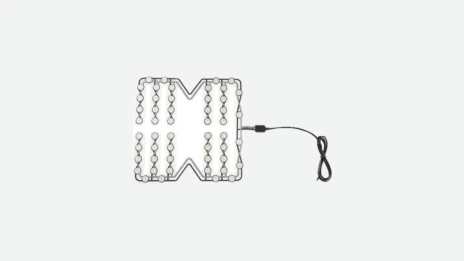
A mat can match the CAD envelope and still respond incorrectly after foam, trim, a housing rib, assembly preload, or cable strain changes the load reaching the sensor. The useful release package therefore controls the relationship among the mat, surrounding mechanics, electronics, assembly process, and test method.
Pressure Sensor Mat Design Starts With the Output Decision
A pressure sensor mat is a thin component that detects load in one or more defined regions. That definition covers several architectures with very different outputs. Some close a contact. Some produce a load-related resistance or voltage after signal conditioning. Others scan many cells to calculate a pressure distribution. The correct architecture is the least complicated one that supplies the decision the controller actually uses.
Before requesting a seat occupancy sensor mat, write the output requirement in one sentence. Examples include “report whether Zone A is active,” “report which of three regions are loaded,” or “measure the spatial pressure distribution across the surface.” Those statements lead to different conductors, channel counts, connectors, electronics, calibration work, and validation plans. For the broader signal chain—from applied load through the controller decision—see how seat occupancy sensors work.
| Architecture | System question it answers | Main design burden | It is not the best choice when… |
|---|---|---|---|
| Contact-switch mat | Is a defined region active or inactive? | Spacer/gap control, closure and release, open/short diagnostics | Quantitative force or a spatial map is required |
| Analog discrete-zone mat | Has load in a named region crossed a calibrated band or threshold? | Mechanical conditioning, excitation/readout circuit, calibration, hysteresis and drift | The project needs traceable high-accuracy force measurement without a suitable reference transducer |
| Multi-zone contact or analog mat | Which named regions are loaded, and in what combination? | More traces, pins, channels, states, edge cases, and fault combinations | Zone identity does not change the controller decision |
| Matrix pressure-mapping array | How is pressure distributed across an area? | Row/column scanning, crosstalk, signal conditioning, software, and cell calibration | A binary presence decision is sufficient |
| Textile or capacitive conformable system | How can a soft or formed surface sense distributed load? | Dielectric/textile variability, shielding, packaging, electronics, and environmental control | A simpler laminated contact structure meets the controlled load case |
Interlink Electronics describes its FSR as a force-sensitive resistor whose resistance changes under load, while Tekscan's FlexiForce guidance treats the actuator, support, loading alignment, electronics, and calibration as one integration problem. Research on flexible piezoresistive arrays shows a different burden: patterned rows and columns reduce external wiring, but matrix scanning introduces crosstalk and per-cell characterization questions. These are useful architecture principles, not proof that every custom mat uses an FSR or a scanned matrix.
A thin laminated mat is also the wrong starting point when the application needs a calibrated load cell, a high-resolution mapping instrument, a dynamic-only piezoelectric response, or a machinery safeguarding device covered by ISO 13856-1. ISO 13856-1:2013 addresses pressure-sensitive protective mats and floors used to safeguard people from hazardous machinery; an embedded occupancy input does not become such a device because both products contain the word “mat.”
Why a Mat That Fits the CAD Outline Can Still Fail
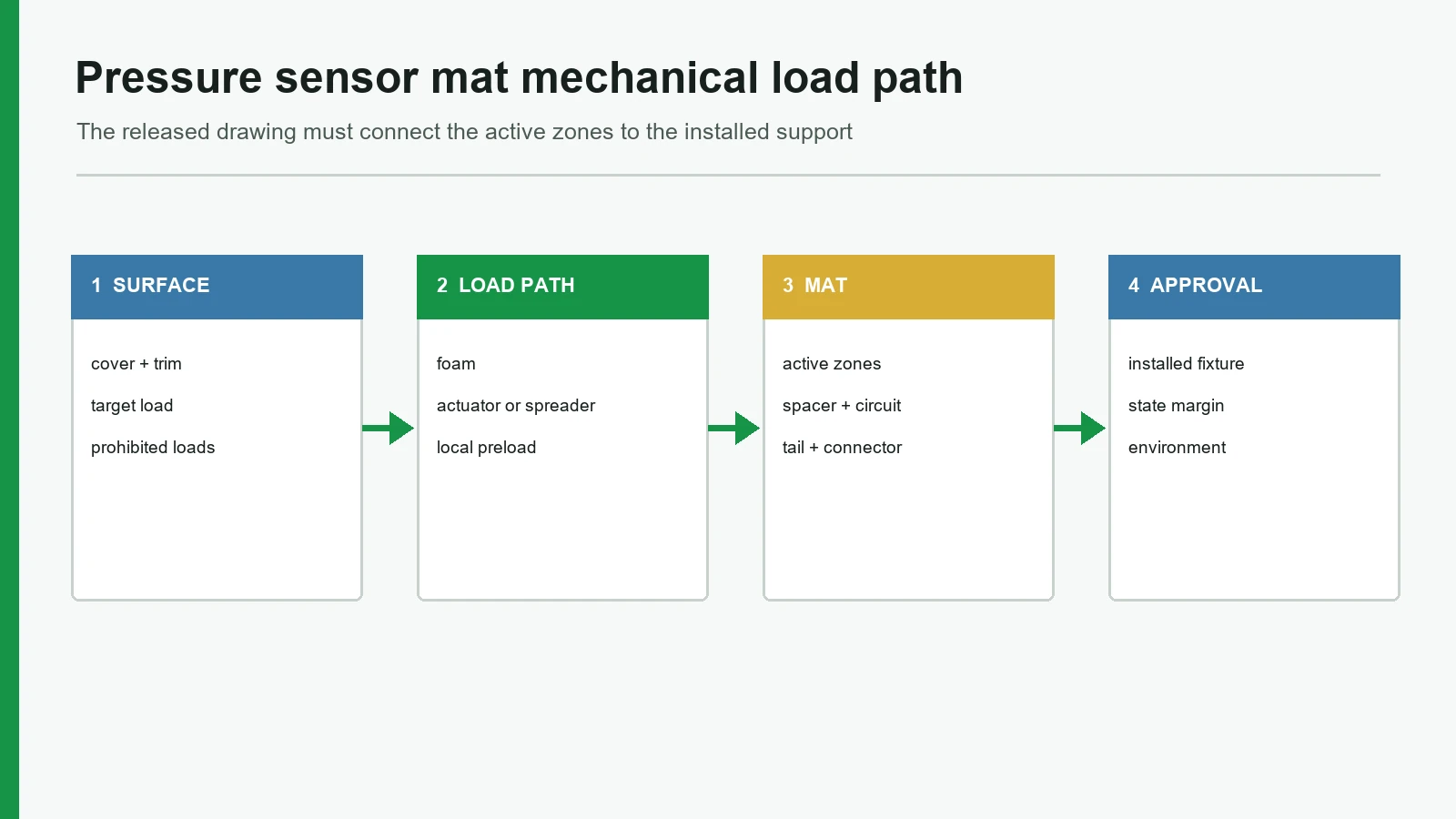
Geometry is only the visible part of the interface. Load travels through covers, foam, actuators, adhesive, and supports before it reaches an active zone. At the same time, die-cut registration, spacer alignment, conductor routing, tail bends, connector strain, and controller thresholds determine whether the mechanical event becomes a reliable electrical state.
Applied load or occupant
Cover, trim, cushion, or equipment surface
Foam, elastomer, actuator, or load spreader
Electrical active zone in the sensor mat
Backing plate, cushion support, housing, or frame
Conditioning circuit → controller decision
A short failure chain helps expose what an outline-only drawing misses.
| Omitted input | Physical mechanism | Observed symptom | Verification method |
|---|---|---|---|
| Foam or actuator section | Load spreads away from, or concentrates inside, a zone | Missed detection or local over-response | Sectioned fixture and mapped load cases |
| No-sense area | Rib, clip, screw boss, or trim preload presses a live region | False active state when nominally empty | Assembly check at tolerance extremes |
| Spacer/contact relationship | Contact gap or travel differs across the zone | Inconsistent closure or release | Load/unload sweep on representative builds |
| Tail transition | Bend or pull reaches converging conductors | Intermittent open circuit after assembly | Continuity monitoring during route and strain trials |
| Lamination datum | Printed contacts, spacer apertures, and cut outline shift relative to one another | Narrow clearance, shifted activation, or short | Layer-to-datum inspection and worst-case stack review |
| Mounting process | Wrinkle, contamination, trapped stress, or premature adhesive contact | Baseline shift, lift, or location error | Controlled assembly trial and visual/functional inspection |
| Controller interface | Excitation, input circuit, timing, or pin map is assumed | Bench sensor “works” but system input does not | Test with production-intent electronics and mating connector |
The lesson is practical: approve a load path and interface, not merely a cut shape.
The 9-Point Custom Pressure Mat Design Framework
A custom pressure mat should pass nine reviews before production release. The sequence follows engineering dependency: output first, then geometry and load transfer, then construction and interconnect, then assembly, evidence, and change control.
1. Define the required decision and output architecture
Start with controller behavior. Identify active, inactive, transitional, and fault states; output type; channel count; timing; and diagnostic assumptions. A contact mat may need a normally open state and open/short diagnostics. An analog zone needs the measurement circuit, expected signal band, sampling method, and downstream threshold logic. A matrix needs cell count, scan strategy, spatial resolution, frame rate, and acceptable crosstalk.
Do not use “pressure” as shorthand for accuracy. An FSR, contact switch, capacitive array, and load cell do not make equivalent measurements. Interlink explicitly distinguishes an FSR from a load cell and strain gauge. If the system decision is only occupied/not occupied, a high-channel-count pressure map may add electronics and calibration without improving the decision.
The requirement names the output, controller interface, states, fault response, and what each channel changes in system logic.
A supplier is asked to choose the technology from only “thin pressure mat” and an outline.
2. Convert equipment CAD into a controlled design envelope
The design envelope must include datums, orientation, installation side, permitted mat area, cutouts, holes, ribs, seams, clips, fasteners, moving mechanisms, high-curvature regions, service access, and the assembly insertion path. Mark prohibited regions by function: no sensor, no conductor, no adhesive, no stiff transition, or no concentrated load.
An internal cutout is not merely an empty shape. Its edge may compress available trace space, concentrate strain, or alter layer registration. Likewise, a mat installed flat has a different mechanical duty from one formed over a compound surface. Dimensions that control zone-to-load alignment deserve different tolerances from cosmetic or reference dimensions.
The CAD package establishes X/Y datums, top/bottom orientation, critical feature classes, mounting references, and explicit keepouts.
The only supplied geometry is an outside length and width, screenshot, or hand-marked photograph.
3. Map pressure sensing zones to load cases and logic
Pressure sensing zones belong where required loads reach the sensor plane—not necessarily at the visual center of a seat, pad, or housing. For each load case, record where load enters, how the mechanical stack distributes it, which electrical zone should respond, which other zones may respond without changing the decision, and which regions must stay inactive.
Use drawing terms consistently:
- Overall outline: the complete cut shape.
- Electrical active zone: the contact or sensing feature.
- Effective detection area: the assembly region where a specified load produces the approved response.
- No-sense area: a region that must not create a valid activation.
- Trace corridor: the protected conductor route from zone to tail.
- Tail transition: the stiffness and geometry change from sensor body to interconnect.
One large zone minimizes routing and state combinations. Several smaller zones can identify front/rear, left/right, or other named load patterns, but each one needs a system purpose. Research comparing pressure-matrix electrode designs reinforces the same general point: more spatial information changes the sensing and processing problem; it is not free coverage.
Every zone has a named load case, output channel, edge-condition test, and controller decision.
Zones are placed by symmetry, or added because a denser drawing appears more capable.
4. Engineer the mechanical load path and load distribution
The sensor receives only the force that survives the mechanical stack. Compliant foam may spread a concentrated input across several zones. A hard actuator may focus load onto a small area. A support gap may let the sensor bend instead of compress. Trim tension, fasteners, adhesive, or the product's own weight can create preload before the target event occurs.
Loading area, alignment, load concentrators, support, and shear control belong in the mechanical specification. Bending near an active area can preload an FSR; shear or creasing can damage a layered sensor. Normal load, shear, support, and alignment require explicit review for every custom mat construction.
Test edge positions, zone gaps, cutouts, ribs, trace corridors, and posture or equipment-position extremes. A center press on a flat bench says little about a curved cushion with assembly variation.
A section drawing and fixture plan define cover, foam or actuator, sensor plane, support, preload, shear, contact area, and alignment extremes.
Finger pressure or one centered dead weight is treated as proof of installed performance.
5. Specify the functional stack, spacer, and lamination
Choose layers by function before choosing brand names or thicknesses. A contact mat, analog resistive zone, matrix array, and capacitive textile do not share one universal construction.
Optional wear or environmental protection
Upper conductor / electrode / circuit carrier
Spacer, controlled gap, resistive medium, or dielectric
Lower conductor / electrode / support carrier
Internal bonding and protected/unbonded regions
Mounting layer or mechanical retention feature
Equipment substrate or cushion support
The spacer may control where contact is possible, where movement occurs, or where a dielectric compresses. Bonded, unbonded, vented, and protected regions must be shown when the architecture requires them. Full-area bonding can inhibit travel; uncontrolled unbonded regions can permit wrinkles, contamination, or layer migration.
Lamination drawings should identify layer datums, active-feature alignment, spacer-to-contact relationship, conductor clearances, adhesive keepouts, internal cutouts, tail-layer alignment, and cut-edge relationships. IPC-2223E provides design requirements for flexible and rigid-flex printed boards, but it applies only when the selected interconnect and customer requirement fall within its scope. It is not a blanket pressure-mat certification.
Each layer has a named electrical, spacing, bonding, protection, or mounting function, plus an inspection reference.
A generic PET/conductive ink/adhesive recipe is frozen before load, environment, output, and assembly requirements are known.
6. Treat conductors, flexible tail, and connector as one interface
The tail is part of the sensor design. Select its exit before zone routing is fixed. Record trace corridors, body-to-tail transition, one-time versus repeated bends, bend direction, adjacent stiff regions, support, strain relief, abrasion risk, connector pull, mating part, pin orientation, and zone-to-pin mapping.
A flexible pressure sensor mat can contain areas with very different bend duties. The body, active zone, transition, tail, stiffener, and connector are not equally flexible. Interlink's integration guide warns against kinking or creasing its tails and against bending near the active area. The article deliberately does not copy its numeric bend limits because those values belong to its named products.
Connector control should include manufacturer and part number once approved, mate, pin count and numbering view, polarization, lock, insertion direction, service access, and continuity checks. “Compatible connector” is not an inspectable interface.
The released package contains approved bends, transition protection, strain relief, mating connector, and a zone-to-pin map.
The tail route is added after zones, mounting points, and connector packaging are frozen.
7. Design the mounting and assembly process
Mounting alters mechanics as well as location. Document substrate material, surface texture, curvature, coating or release agents, cleanliness, installation temperature, access for placement pressure, fixture or alignment features, rework requirement, and expected environmental exposure.
3M's 2017 VHB surface-preparation bulletin shows why “self-adhesive” is not a process specification: the approved preparation depends on substrate and bonding system. That source does not mean a JASPER design uses VHB tape. It supports the narrower point that the exact adhesive supplier's data and the real substrate must drive surface preparation.
Assembly instructions should prohibit stretching the mat to fit, pulling the body with the tail, folds through active zones, wrinkles, unsupported bridging, trapped cable tension, and uncontrolled rubbing at cut edges. If manual placement cannot hold a critical zone-to-datum relationship, use an alignment feature or fixture.
A work instruction controls surface condition, placement datum, sequence, fixture, rework, and inspection.
“Peel liner and apply” is the complete installation method.
8. Build prototype evidence in stages
Prototype work should reduce uncertainty in a deliberate order. Start with geometry and fit, then functional response, then unit-to-unit and assembly variation, followed by environmental and misuse conditions relevant to the application. Use the real controller or a production-representative circuit before approving thresholds.
NIST's measurement-process framework separates repeatability, longer-term reproducibility, bias, stability, calibration, gauge studies, and uncertainty. Those categories prevent a common mistake: reporting an average from one sensor and one fixture as if it proves production behavior.
The prototyping process should close open geometry and interface questions before production tooling or documentation is fixed. The separate testing and validation capabilities page can support planning, but the OEM and finished-system owner must define the applicable conditions and acceptance criteria.
The plan names samples, equipment builds, positions, load cases, circuits, conditions, repetitions, acceptance limits, and responsibility for every stage.
One center-load result on one mat and one assembly is called validation.
9. Define change-control triggers and the application boundary
A pressure mat is approved inside a configuration. Changes to foam density or shape, trim tension, support geometry, zone layout, spacer, adhesive, mounting position, tail route, connector, excitation circuit, firmware threshold, or assembly method can alter response. The drawing and validation plan should state which changes require review, partial requalification, or full revalidation.
The component boundary matters just as much. A seat mat may provide an input to warning or occupant-detection logic, but the vehicle system owner validates the complete function. A component built for medical or assistive seating does not confer finished-device biocompatibility, electrical safety, cleaning validation, clinical performance, or regulatory approval. A general occupancy input does not replace an ISO 13856-1 machinery-safety mat.
A controlled list connects each design or process change to an assigned review and evidence action.
A similar outline is assumed to deliver equivalent behavior in another seat, cushion, machine, or controller.
Framework closeout: release ownership
The nine criteria fail when responsibility is implicit. Use the same owner names in the requirement, drawing review, prototype report, and change notice.
| Controlled item | Primary owner | Required approval evidence | Revisit when… |
|---|---|---|---|
| System decision and fault behavior | OEM systems team | Interface or functional requirement | Controller logic, use case, or hazard analysis changes |
| Envelope, load path, and mounting | OEM mechanical team | CAD, section drawing, fixture/load plan | Foam, trim, support, substrate, or assembly changes |
| Zones, conductors, tail, and connector | Sensor plus OEM electrical teams | Zone drawing, pin map, mating-interface review | Zone logic, tail route, connector, or circuit changes |
| Layer stack and lamination controls | Sensor manufacturer | Controlled construction and inspection plan | Material, spacer, bonding, print, or cutting process changes |
| Prototype and release evidence | OEM quality/system owner | Approved matrix, raw-data traceability, disposition | Acceptance criteria, configuration, or test method changes |
A Six-Step OEM Specification Process
The framework becomes manageable when the project team follows the same sequence for every new design.
Step 1 — Write a one-page decision sheet
State the system decision, output type, channels, active/inactive/fault behavior, timing, controller interface, and application boundary. If the project needs only presence detection, say so. If it needs pressure distribution, state the required spatial information and why. This prevents an expensive array from solving a binary question—or a contact switch from being expected to report force.
Step 2 — Release the mechanical input package
Provide controlled CAD with datums, orientation, permitted envelope, cutouts, ribs, seams, moving parts, prohibited areas, sensor plane, mounting substrate, and assembly route. Add a section through the complete stack. Identify load positions, contact areas, directions, dwell, and mechanical extremes rather than only nominal weight.
Step 3 — Approve zones and interfaces before materials
Review electrical active zones, effective detection areas, no-sense regions, trace corridors, tail transition, tail exit, connector location, and zone-to-pin map. Cross-check every zone against controller logic. Only then should the project lock layer functions, conductor approach, spacer/gap concept, lamination map, mounting system, and protective features.
Step 4 — Build fit and functional prototypes
The first samples should confirm outline, cutouts, zone alignment, tail route, connector access, and assembly sequence. The next set should exercise required loads, no-sense cases, edges, gaps, loading and unloading, preload, continuity, and the real input circuit. Calibration belongs after the representative mechanical stack is stable; the companion pressure sensor mat calibration guide covers threshold, hysteresis, and guard-band development.
Step 5 — Challenge variation and foreseeable misuse
Use multiple sensor samples and multiple representative equipment builds. Test alignment extremes, repeated assembly, relevant environmental conditioning, cable handling, concentrated or off-axis loading, and defined fault cases. Medical, automotive, and industrial programs will have different hazards and standards; the system owner selects the applicable plan.
Step 6 — Release evidence, owners, and change control together
Do not release only a sensor drawing. Approve the material and layer specification, zone-to-pin map, assembly instruction, critical-to-function dimensions, prototype report, open-risk list, production inspection plan, change triggers, and responsibility split. A requirement without a named owner usually becomes a late dispute.
Prototype and Sample Approval Test Matrix
This matrix is a procurement-preparation tool, not a universal test standard. Conditions, sample quantities, cycles, and acceptance limits must come from the application's risk analysis and controlled requirements.
| Stage | Representative evidence | Questions to close | Release output |
|---|---|---|---|
| 1 — Geometry and fit | Controlled CAD, cut samples, equipment/seat build, connector mate | Does the mat fit without folds, interference, tail strain, or inaccessible assembly steps? | Approved outline, datums, keepouts, tail exit, assembly direction |
| 2 — Functional response | Required and prohibited load cases, edges, zone gaps, load/unload, production-intent circuit | Does each zone produce the intended state or signal, and remain inactive where required? | Approved zone map, pin map, preliminary electrical limits |
| 3 — Variation and environment | Multiple mats and builds, alignment extremes, relevant conditioning, cable/connector handling | Are repeatability, reproducibility, stability, and fault responses acceptable? | Characterization report, risk updates, proposed acceptance limits |
| 4 — Production release | Drawing inspection, assembly trial, end-of-line method, change-control review | Can manufacturing detect wrong geometry, layer shift, open/short, connector, and placement errors? | Released drawing/BOM, work instruction, inspection/test plan, change list |
A useful sample-approval record identifies the measurement reference, fixture revision, equipment build, sensor revision, circuit revision, software revision, operator or automated method, raw data location, and disposition. That traceability matters more than a polished graph without configuration details.
Supplier Release Blockers That Stop a Pressure Mat Project
These issues should pause design release regardless of a supplier's price or responsiveness:
- One universal stack is proposed before requirements review. Architecture and materials are being selected without the output, load path, or environment.
- Active area and overall outline are used interchangeably. Non-sensing borders, traces, transition, and effective detection area are uncontrolled.
- No one asks for the mating connector or controller circuit. The electrical interface is being deferred until samples fail to integrate.
- A catalog bend radius is copied to a different construction. Product-specific guidance is being presented as a universal rule.
- Only center loading is tested. Edges, gaps, no-sense areas, preload, alignment, and support variation remain unknown.
- The supplier promises finished-system compliance from a component drawing. Vehicle, medical, and machinery responsibilities are being blurred.
- Layer registration and die-cut relationships have no inspection method. A tolerance exists on paper but cannot be verified in production.
- The assembly process is reduced to adhesive backing. Surface state, alignment, wrinkles, rework, and strain are unmanaged.
- Thresholds are fixed before mechanics stabilize. Firmware may be compensating for an unresolved load-transfer problem.
- Changes to foam, trim, support, mounting, or electronics trigger no review. The approved configuration has no boundary.
Application Fit: Where a Flexible Pressure Sensor Mat Works—and Where It Does Not
A flexible pressure sensor mat fits applications that need thin, distributed detection under a controlled mechanical stack. Examples include seat occupancy inputs, operator-presence seats, smart furniture, position zones in cushions, and bounded load-distribution sensing. Automotive HMI and sensing applications often add strict packaging, connector, traceability, environmental, diagnostic, and system-validation requirements.
| Application | Suitable design question | Main integration risk | Boundary |
|---|---|---|---|
| Passenger or commercial-vehicle seat | Is a defined seat region occupied, or which named zones are loaded? | Foam/trim variation, preload, posture, tail routing | Vehicle warning, classification, and restraint logic remain system-owned |
| Operator-presence seat | Is the operator in the required position? | Transitional states, vibration, faults, cushion change | Machine risk reduction requires system-level analysis; ordinary seat mats are not safety mats by default |
| Smart furniture or equipment seating | Is a seat/region occupied or how is load distributed? | Replaceable cushions, user variation, service routing | Consumer claims and privacy/data functions need separate review |
| Medical or assistive seating component | Does a defined component detect a bounded load condition? | Cleaning exposure, pressure distribution, cable handling | Finished-device safety, biocompatibility, clinical performance, and regulatory approval are not component-manufacturing claims |
| Pressure mapping or ergonomic analysis | What spatial distribution exists across the contact surface? | Cell calibration, crosstalk, scan electronics, software | A discrete contact mat is usually too simple |
| Machinery safeguarding floor | Does a protective floor detect a person before hazardous motion? | Safety architecture, minimum performance, installation, validation | Use a purpose-designed system assessed to applicable requirements such as ISO 13856-1; do not substitute an embedded occupancy mat |
The recommended laminated contact or zone construction is not the best choice when the project needs metrology-grade absolute force, dense spatial mapping, dynamic impact-only sensing, stretchable textile behavior, or a certified protective-device function. Choose the measurement and safety architecture first.
Drawing Checklist: What to Submit for Design Review
For efficient pressure sensor mat design review, send one controlled package rather than separate emails with disconnected dimensions. JASPER can be considered as one manufacturing and development option after the input boundary is clear; the same checklist is suitable for evaluating any qualified supplier.
- Product or seat CAD with units, datums, orientation, revision, and sensor plane.
- Permitted envelope, cutouts, holes, ribs, seams, clips, and prohibited regions.
- Section drawing through cover, foam/actuator, sensor, support, and mounting layer.
- Required active, inactive, transitional, and fault states.
- Load cases with position, direction, contact area, dwell, and repetition.
- Required contact, analog, multi-zone, matrix, or conditioned output.
- Purpose and effective coverage requirement for every sensing zone.
- Tail exit, route, one-time or repeated bends, length, and strain-relief concept.
- Connector and mating-part drawing, pin numbering view, and zone-to-pin map.
- Excitation/readout circuit, supply, ADC or digital input, sampling, timing, and diagnostics.
- Substrate, mounting, assembly, environment, cleaning, handling, and service conditions.
- Prototype quantities, equipment builds, fixtures, acceptance matrix, and responsible owners.
- Traceability, labeling, packaging, annual planning volume, and change-control requirements.
Unknown values should be labeled open. They should not be replaced with a generic catalog number. To begin a review, submit a project brief with dimensions, active zones, output requirements, installation section, tail route, and connector interface.
Frequently Asked Questions
What information is needed for pressure sensor mat design?
Start with the controller decision, output architecture, mechanical envelope, load path, pressure sensing zones, no-sense regions, stack section, tail route, connector, mounting substrate, environment, prototype plan, and acceptance method. A cut outline alone cannot define how the mat behaves in the finished assembly.
Is the active area the same as the overall mat size?
No. The overall outline can include non-sensing borders, conductors, adhesive, labels, protective regions, cutouts, and the tail transition. The effective detection area can also differ from the electrical active zone because foam, covers, actuators, and supports redistribute load.
How many pressure sensing zones should a custom pressure mat use?
Use the fewest zones that support the controller's required decision, coverage, and diagnostics. Every added zone creates routing, pin or scanning, calibration, edge-case, fault, and validation work. If zone identity never changes system behavior, the extra channels may not be justified.
Can a flexible pressure sensor mat bend?
Some regions can flex, but the allowable bend depends on construction, location, direction, and duty. The active body, body-to-tail transition, tail, stiffener, and connector may have different limits. Define whether each bend occurs once during assembly or repeatedly in operation, then validate that exact route.
Should a pressure mat be calibrated before installation?
Component characterization can begin before installation, but final thresholds or load relationships should be developed and verified in the representative mechanical stack with production-intent electronics. Foam, support, preload, alignment, mounting, and the input circuit can all change the observed signal.
Which mounting adhesive should an OEM specify?
There is no universal choice. Selection depends on the carrier, substrate, surface energy and texture, environment, service requirement, assembly process, and the adhesive's effect on sensor movement. Follow the chosen supplier's current technical data and validate the complete mounted assembly.
Can one pressure mat design be reused in several products?
Only after confirming that the envelope, load path, foam or actuator, support, mounting, zone logic, tail route, connector, electronics, environment, and acceptance conditions remain equivalent. A similar outside shape does not prove equivalent sensing behavior.
Is a seat occupancy mat the same as a machinery safety mat?
No. ISO 13856-1 addresses pressure-sensitive protective mats and floors used for machinery safeguarding. A seat occupancy or equipment input mat should not be represented as a protective device unless the complete product, control architecture, installation, and validation meet the applicable safety requirements.
Technical References
- Source: IPC-2223E flexible and rigid-flex printed board design. Accessed 2026.
- Source: NIST measurement process characterization. Accessed 2026.
- Source: 3M pressure-sensitive adhesive surface preparation guidance. Accessed 2026.
- Source: ISO 13856-1 pressure-sensitive protective devices scope. Accessed 2026.
- Source: Peer-reviewed flexible piezoresistive array design research. Accessed 2026.
- Source: Tekscan FlexiForce integration resources. Accessed 2026.
- Source: Tekscan pressure sensing mat systems. Accessed 2026.
- Source: Fraunhofer CeSMA configurable pressure sensing mat. Accessed 2026.
- Source: 3M substrate surface considerations for adhesive selection. Accessed 2026.
- Source: IPC board design standards scope. Accessed 2026.
- Source: Interlink Electronics, *FSR 400 Series Integration Guide. Accessed 2026.
- Source: Tekscan, FlexiForce Integration Guides and mechanical integration resources. Accessed 2026.
- Source: Recent Advances in Flexible Piezoresistive Arrays: Materials, Design, and Applications. Accessed 2026.
- Source: ISO, *ISO 13856-1:2013 — Safety of machinery — Pressure-sensitive protective devices — Part 1. Accessed 2026.
- Source: Embodiment Lab, *Optimizing Pressure Matrices: Interdigitation and Interpolation Methods. Accessed 2026.
- Source: IPC, IPC-2223E: Sectional Design Standard for Flexible/Rigid-Flexible Printed Boards, official scope. Accessed 2026.
- Source: 3M, Surface Preparation for 3M VHB Tape Applications — Technical Bulletin, October 2017. Accessed 2026.
- Source: NIST/SEMATECH, *Engineering Statistics Handbook, Chapter 2: Measurement Process Characterization. Accessed 2026.
- Source: Wireless pressure monitoring system utilizing a 3D-printed Origami pressure sensor array*, npj Flexible Electronics, April 3, 2024. Accessed 2026.
- Source: IPC, Board Design Standards — IPC-2223 design-scope overview. Accessed 2026.
- Source: NIST, publication record for NIST/SEMATECH Engineering Statistics Handbook, Chapter 2, June 1, 2003. Accessed 2026.
- Source: Tekscan, FlexiForce Integration Resources — mechanical, electrical, calibration, and prototyping index. Accessed 2026.
- Source: 3M, *Substrate Surface Consideration for Adhesive Selection. Accessed 2026.
- Source: Tekscan, Pressure Sensing Mat Systems — pressure-distribution system category and application overview. Accessed 2026.
- Source: Fraunhofer/CeSMA, Pressure Sensing Mat — configurable textile/capacitive sensing-point example. Accessed 2026.
- Source: Tekscan, Custom Tactile Pressure Sensors — public upper capability reference of 1,600 sensing elements/in² (248/cm²). Accessed 2026.
- Source: IATF, Certification Bodies — Under Contract — official list of IATF-recognized certification bodies. Accessed 2026.
- Source: ISO, *ISO 9001:2015 — Quality management systems — Requirements. Accessed 2026.
Freeze the pressure mat drawing inputs
Send the active zones, prohibited areas, load path, tail and connector, mounting process, environment, and acceptance evidence.