
Choose screen printing for stable spot colors, engineered opaque or transparent layers, and repeat releases. Choose digital for gradients, photographs, many variants, short runs, or frequent revisions. Use hybrid only when a named layer function earns the added interfaces.
JASPER certifications: ISO 9001, ISO 13485, IATF 16949, and ISO 14001.
1. Quick Verdict: Choose by Graphic Function and Release Pattern
Screen printing usually leads when an overlay uses a small, stable set of solid colors and purpose-built layers such as opaque white, transparent window color, dead-front masks, or a printed texture. Digital printing usually leads when the file contains continuous gradients, photographic imagery, multiple versions, serialized information, or unsettled artwork. Quantity matters, but it is not a stand-alone rule. These are process tendencies synthesized from Nazdar's membrane-overlay ink data, Mimaki's plate-free UV inkjet guidance, and Tekra's overlay-film comparison, not performance guarantees.
| Project condition | Screen printing usually leads | Digital printing usually leads | Decision boundary |
|---|---|---|---|
| Stable solid spot colors | ✓ | Approve the mixed ink on the actual film and finish; a color name alone is not acceptance evidence. | |
| Photographs and smooth gradients | ✓ | Screen halftones are possible, but digital output normally avoids one stencil and registration sequence per color. | |
| Frequent artwork revisions | ✓ | A digital file can change without remaking color-specific screens; a new proof is still required. | |
| Many language, model, or serial variants | ✓ | Confirm the RIP, variable-data controls, inspection, and file-to-part traceability. | |
| Repeat releases of unchanged artwork | ✓ | Screen setup can be amortized only if the screens, ink recipe, material, and approval reference remain controlled. | |
| High-opacity, dead-front, or transparent functional layers | ✓ | Digital white and multilayer modes also exist; compare qualified builds rather than assuming one-pass opacity. | |
| Selective printed textures or specialty screen inks | ✓ | Use only an ink/film/cure combination qualified for the downstream converting sequence. | |
| Fast appearance prototypes | ✓ | A digital prototype does not automatically predict a later screen-printed production part. | |
| Subsurface printing behind clear film | ✓ | ✓ | Subsurface describes layer position. Either imaging method can be used if the film and ink system are compatible. |
| Durability in service | Depends on film treatment, ink chemistry, cure, hardcoat, layer order, edge exposure, cleaning, UV, and test conditions. |
The practical verdict is conditional: select screen for stable, layer-driven artwork; select digital for image complexity and change; qualify a hybrid when one method cannot meet the optical and production requirements alone. If chemical exposure, backlighting, or an unusual film grade drives the design, neither route should be released until production-intent coupons and an assembled first article pass the agreed checks.
2. How the Two Graphic Overlay Printing Methods Work
The two graphic overlay printing methods differ in how they create and change the image. Screen printing transfers ink through open areas in a mesh stencil. Digital printing images the file without a color-specific physical screen, using a platform such as UV inkjet or liquid electrophotography. “Digital” is therefore a production class, not an ink specification; “screen” does not define one mesh, deposit, or cure condition.
Screen printing: a controlled stencil and ink sequence
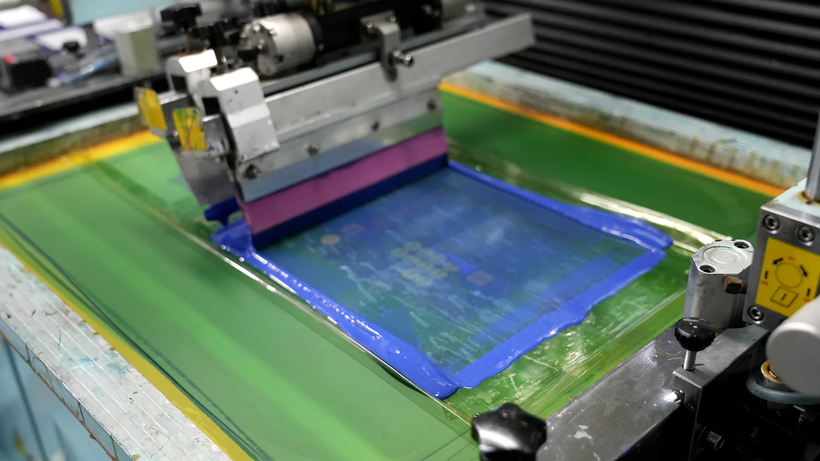
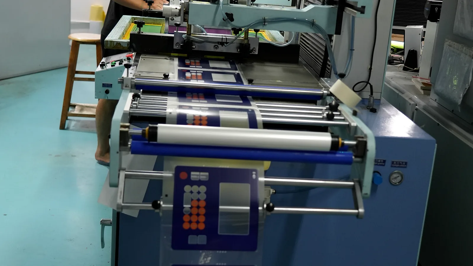
A screen printed graphic overlay is built one printed separation at a time. Artwork is separated by color or function; each separation becomes a stencil; the press pushes its specified ink through the mesh; the layer is dried or cured; later colors, white, blocking, window, or texture layers follow in registration. ISO 12647-5:2015 formalizes process control for four-color screen printing from data preparation through production, although it does not set overlay durability or spot-color tolerances.
Screen flow: controlled artwork → color/function separations → screen preparation → ink setup → print and register each layer → cure or dry → inspect → emboss, laminate, and cut
Screen printing is not limited to flat colors. Nazdar's screen-ink catalog describes CMYK halftone dots for full-color reproduction and identifies mesh, squeegee, and press mechanics as variables that affect shade and density. The useful distinction is that screen gradients need halftone separations, controlled dot formation, and multi-screen registration; digital workflows normally render tonal transitions directly from raster data.
Ink laydown is configurable rather than universally “thick.” Mesh opening, stencil build, ink rheology, squeegee settings, print passes, and cure shrinkage all matter. SAATI's Hi-R mesh data publishes different theoretical wet volumes for different mesh constructions, but those values are not transferred or dry-film thickness. A supplier should report the actual build when thickness affects embossing, lamination, window optics, or fit.
Digital printing: plate-free imaging with equipment-specific ink channels
A digital printed graphic overlay moves from the approved file through a RIP and device profile to the printer. The platform may place CMYK, light colors, white, clear, or primer in one or several imaging passes. Film treatment, head technology, drop mode, print direction, white-layer strategy, and cure remain part of the process.
Digital flow: controlled artwork → preflight and RIP → profile and layer order → digital imaging passes → cure → inspect → emboss, laminate, and cut
Representative equipment shows why “digital” cannot be treated as one fixed result. Mimaki's UJF-6042 MkII e lists up to 1200 × 1200 dpi, CMYK, white, clear, and a variable-data workflow. EFI's Pro 30f+ lists reverse printing on clear media, white backing, variable-drop imaging, and multilayer modes. These are examples, not minimum overlay specifications and not JASPER equipment claims.
Subsurface printing is a layer position, not a third imaging method
Subsurface printing places the image on the rear of a transparent film so the user views it through the film. Both screen and digital systems can produce that construction when the chosen film surface accepts the ink. JASPER's verified graphic overlay printing capability lists screen or digital route selection and subsurface printing for suitable clear-film builds.
Typical subsurface overlay stack, user side to enclosure:
Operator, glove, cleaner, and ambient light
Optional first-surface hardcoat or texture
Transparent PET or polycarbonate carrier film
Rear-printed color, legend, and window-border layers
White, blocking, translucent, or dead-front layers as required
Pressure-sensitive adhesive with window and service keep-outs
Enclosure, display, LEDs, or switching assembly
This stack shields rear-printed ink from direct finger and wipe contact. It does not make the front film, hardcoat, cut edge, ink-to-film bond, or adhesive interface immune to exposure. Tekra's ProTek hardcoated PET illustrates the functional split: a first-surface hardcoat addresses wear, while the second surface accepts printing. Teams that also need electrical switching should separately define the graphic overlay versus membrane switch boundary.
3. Side-by-Side Engineering Comparison
This table compares process architecture, not unqualified performance. It is grounded in Nazdar's overlay-specific screen-ink data, Mimaki's UV inkjet configuration, ISO 23498:2022 for printed-white opacity measurement, and Tekra's coated-film inkjet comparison. The quoted supplier must still identify the actual material, ink, equipment class, layer order, cure, and acceptance plan.
| Dimension | Screen printing | Digital printing | What the drawing or RFQ must define |
|---|---|---|---|
| Image carrier | One physical screen/stencil per color or functional separation | Plate-free file imaging through a RIP; passes and channels depend on the device | Controlled file revision, separated functions, and print direction |
| Solid and spot colors | Individually mixed inks suit controlled solid-color programs | CMYK/extended gamut, device spot channels, or separately prepared spot systems vary by platform | Color reference, physical proof, film, backing, finish, lighting, and tolerance method |
| Gradients and photographs | Possible through process-color halftones; dot formation and registration require control | Usually the more direct route for continuous-tone raster art | Source image quality, raster settings, profile, minimum detail, and proof condition |
| Ink laydown | Adjustable through mesh, stencil, rheology, squeegee, and passes | Adjustable through drop mode, passes, channels, white/clear layers, and RIP settings | Finished layer build or optical result where it affects function |
| White and light blocking | Purpose-built opaque inks and repeated screen layers are common options | White channels and multilayer modes are available on qualified equipment | Test the actual white build; do not specify “opaque” without a method and limit |
| Transparent and tinted windows | Transparent screen inks can form controlled lens colors | Digital transparent-color capability depends on ink set, profile, and film | Transmission/color target, light source, viewing state, and clear-zone defect rules |
| Artwork revisions | Changed separations may require new screens and setup | File changes avoid remaking color-specific screens | Revision frequency, approval cycle, obsolete inventory, and traceability |
| Versions and variable data | Separate screens or combined fixed artwork may be needed | Strong fit for serialized, language, model, and image variants when workflow controls exist | Version count, data source, inspection, barcode/serial verification, and file naming |
| Repeat production | Can suit long, stable programs after setup is controlled | Can also run production quantities; economics depend on device mode and ink coverage | Annual volume, release size, nest, setup, spoilage, rate, and repeat-order controls |
| Film compatibility | Ink series must match PET/PC grade, treatment, surface, and downstream conversion | Digital film may need a print-receptive coating or primer matched to the ink | Exact film grade, print side, treatment, hardcoat, storage, and handling |
| Subsurface printing | Available on compatible clear film | Available on compatible clear film and equipment/layer order | Viewed side, reversed artwork, white/blocking order, adhesive contact, and windows |
| Durability | Not guaranteed by the screen process name | Not guaranteed by the digital process name | Complete construction, exposure, specimen, method, endpoint, and acceptance owner |
Two shortcuts should be rejected. First, screen does not automatically mean “durable”; undercured or incompatible screen ink can fail. Second, digital does not automatically mean “thin, weak, or translucent”; current platforms can print white and multiple layers. The defensible comparison is between two quoted, production-intent constructions tested under the same conditions.
The finished stack decides.
4. Where a Screen Printed Graphic Overlay Wins
A screen printed graphic overlay is strongest when the artwork is stable and each printed separation performs a clear optical or manufacturing job. Its advantage comes from controllable inks, meshes, stencils, and layer order—not from the word “screen.”
Stable solid colors with a physical approval reference
Screen printing allows each solid color to use a separately prepared ink rather than relying only on a fixed process-color gamut. That makes it a practical route for controlled brand colors, safety legends, high-contrast icons, and large solid fields. Approval still belongs on the selected film and finish. A Pantone or RAL callout is a target; substrate color, surface texture, ink deposit, backing, and viewing light can change what the observer sees.
For process-color screen work, ISO 12647-5:2015 provides a production-control framework. For a spot-color overlay, the supplier should instead document the ink recipe, mesh/stencil, print order, cure, physical master, viewing condition, and allowed comparison method. Neither route supports a universal “exact match” claim.
Opaque, transparent, dead-front, and texture layers
Overlay-specific screen ink families show the range of functions available. Nazdar 3400 is designed for second-surface membrane-overlay printing on polycarbonate and some top-coated polyester, with variables for opacity, adhesive contact, mesh, and cure. Nazdar 8800 Color Vue includes opaque and transparent lens colors and requires complete drying before cutting, embossing, or adhesive lamination. Marabu's MaraSwitch MSW is another product-specific example for polycarbonate and coated polyester.
These sources support capability, not a blanket result. A dead-front mask that looks black when unlit and reveals an icon when lit must be approved with the actual LED spectrum, brightness, ambient light, film, color layers, white/blocking build, air gap, and viewing angle. The same rule applies to tinted windows and selective textures.
Stable repeats that can retain process knowledge
Once artwork, screens, ink recipes, film, print order, cure settings, and an approved master are controlled, repeat releases can reuse process knowledge and distribute setup across more accepted parts. This is where screen economics often improve. The phrase “high volume” is incomplete, though: two colors on a dense sheet nest and eight colors with several optical layers do not carry the same setup, registration, drying, or spoilage burden.
Screen is not the best choice when the image changes often, contains many photographs or tonal variants, needs per-part variable data, or has not passed artwork review. It may also be the wrong route for a tiny pilot lot if color-specific screen preparation and setup dominate the accepted-part cost. Those conditions point to digital sampling or a staged process trial—not to lowering the approval standard.
5. Where a Digital Printed Graphic Overlay Wins
A digital printed graphic overlay is strongest when image complexity or change carries more cost and risk than color-specific tooling. Digital removes physical screens from image generation; it does not remove preflight, profiling, physical proofing, cure control, or film qualification.
Gradients, photographs, and dense multicolor artwork
Digital imaging normally handles continuous-tone data, fine transitions, shadows, and photographic content with fewer prepress separations than screen halftones. Equipment capability still sets the boundary. Mimaki publishes up to 1200 × 1200 dpi for the UJF-6042 MkII e; EFI publishes 5 pL variable drops and up to 1200 × 1200 dpi for the Pro 30f+. Those values show an upper equipment mode, not a required overlay resolution, and neither proves that the resulting ink adheres to a chosen film.
The art proof must preserve minimum text, line, barcode, and icon requirements after the actual RIP, white-layer order, reverse imaging, lamination, and cutting sequence. A high addressable resolution cannot rescue poor source artwork, an incompatible coating, excessive ink build, or uncontrolled dot gain.
Many versions, frequent revisions, and variable data
Plate-free imaging makes a file change materially different from a screen change. Mimaki's UV inkjet process comparison identifies a separate stencil for each screen color and positions UV inkjet for small, varied runs. Digital workflows can therefore fit language sets, model variants, serials, QR codes, or late artwork changes—provided the data source, imposed file, RIP output, and inspection record remain traceable.
Revision speed has a limit. Every new color, white mask, window border, serial-data rule, or cut relationship can change the accepted appearance or geometry. File release, proof approval, and first-article controls still apply; “same material, new PDF” is not enough for an appearance-critical interface.
Appearance prototypes and low-release quantities
Digital printing often reduces the fixed image-creation work for early samples because no color-specific screens are prepared. That makes it useful for testing artwork hierarchy, overall appearance, language variants, and enclosure fit before the design freezes. If production will later move to screen printing, the digital sample should be labeled an appearance model unless color, opacity, texture, thickness, and durability are requalified in the production process.
Digital is not the best choice when a stable program needs a few controlled spot colors, a screen-specific functional ink, a qualified selective texture, or an optical build the available digital equipment cannot reproduce on the selected film. It is also a poor choice when the supplier cannot identify the ink–coating compatibility. Tekra's overlay-specific comparison found ink removal on its uncoated polycarbonate but retention on its print-receptive coated film under the supplier's cross-hatch check; that product-level result illustrates why “UV digital” is not an adhesion specification.
6. When Hybrid or Subsurface Printing Is the Better Construction
A hybrid overlay uses digital and screen printing in one controlled layer stack. A credible reason might be digital CMYK imagery or versioned content followed by a screen-printed spot color, opaque white, dead-front mask, transparent lens color, or selective texture. The functions must be assigned before quoting; “hybrid for better quality” is not a specification.
| Layer function | Likely route | Why it may fit | New interface to validate |
|---|---|---|---|
| Photographic or gradient image | Digital | Direct raster imaging and efficient version changes | Digital ink to film; image to later screen-layer adhesion |
| Controlled solid spot color | Screen | Separately mixed ink and controlled deposit | Registration to digital image; cure compatibility |
| White or blocking layer | Screen or digital multilayer | Optical density can be built by either qualified route | Measured opacity, layer order, cure, cracking, and adhesive contact |
| Dead-front or tinted window | Screen or qualified digital build | Requires controlled lit/unlit behavior rather than a generic color | Transmission, haze, light leakage, viewing angle, and register |
| Printed texture or clear effect | Often screen; some digital platforms offer clear | Selective surface or optical function | Surface height, full cure, adhesion, embossing, and cosmetic limit |
Hybrid manufacturing is technically real, but it is chemistry-specific. Nazdar 3400 documents one route for screen overprinting HP Indigo output with 5% by weight NB80 adhesion promoter. That instruction proves one qualified combination can exist; it is not a recipe for another ink, digital press, film, primer, or adhesive. Any hybrid quote should name the layer order and require intercoat adhesion after the final cure and downstream conversion.
Subsurface printing can be screen, digital, or hybrid. Its value is physical placement: the clear carrier stands between the printed image and direct user contact. It is not the best construction when the intended substrate is opaque, the image must be tactile on the exposed face, a special first-surface effect is required, or cut-edge chemical ingress remains unacceptable. A thicker or harder face film can also alter key feel, emboss response, display clarity, and glare; the complete HMI stack decides the tradeoff.
Hybrid is not the best choice for simple artwork that one qualified process can produce. A second imaging route adds make-ready, registration, cure sequencing, work-in-process handling, intercoat risk, and another approval dependency. Use it only when a named layer function earns that complexity.
7. Volume and Cost: There Is No Universal Break-Even Quantity
The screen-versus-digital crossover must be quoted for the actual overlay. A published claim such as “screen above 500 pieces” hides the variables that create the number. A four-color image, three spot colors plus white, or a six-layer dead-front build can each produce a different crossover at the same finished quantity.
Volume alone cannot decide it.
Use this model:
Total accepted-part cost = prepress and tooling + run conversion + version/changeover work + expected spoilage and revalidation + inventory and obsolescence risk
For screen printing, ask the supplier to show the effect of color count, number of screens, mesh/stencil class, transparent or opaque layers, ink preparation, cure sequence, sheet nest, make-ready sheets, retained/remade screens, release size, repeat-order interval, and artwork changes. For digital printing, ask for the device/ink class, print mode, white/clear/primer passes, ink coverage, coated-film or primer requirement, sheet nest, version changes, throughput mode, cure, maintenance allowance, and the same finishing operations.
Equipment data reinforce why a generic breakpoint fails. The sheet-fed SPS Vitessa SL lists a nominal maximum of 4,000 impressions per hour and accepts substrates down to 0.07 mm on one model. Mimaki and EFI publish digital performance by resolution, pass, ink-channel, and media mode. None of those nameplate values equals accepted overlay throughput after color changes, white layers, curing, inspection, nesting, lamination, or cutting. They are representative equipment limits, not JASPER process data.
Public planning references for comparable RFQs
Evidence boundary: The values below come from named public sources and show how an OEM can make two RFQs comparable. They are not JASPER capabilities, guaranteed lead times, universal process limits, or released drawing requirements. The quoted supplier must confirm every value for the actual film, artwork, layer order, converting process, and inspection setup.
| RFQ field | Public reference value | Why this value is useful | Boundary that must stay with it |
|---|---|---|---|
| Quantity for paired screen/digital quotes | 500 finished parts | One public overlay-printing comparison places its crossover around 500 pieces, making that quantity a useful point at which to request both quotes. | This is a comparison quantity, not a JASPER MOQ or a universal break-even. Color count, area, white/blocking layers, variants, nest, and revisions can move the crossover. |
| Appearance-prototype planning lead | 7 business days after approved artwork and design inputs | One public overlay supplier publishes samples within seven business days of design approval, within a broader public supplier band of roughly one to two working weeks. | Treat this only as a sourcing comparison point. Material sourcing, customer changes, special testing, production load, and transit are excluded. |
| Critical solid-color acceptance target | ΔE00 ≤ 2.5 against the approved physical master | 3M Corporate General Specification 1200 assigns a 2.5 ΔE00 tolerance to primary line colors for digital inkjet and stamp/pad/screen printing. | Use the same production film, finish, backing, aperture, illuminant, observer, instrument mode, and formula. This broader print specification is a planning reference, not an overlay standard or proof of JASPER capability. |
| Small-format screen print-to-print registration target | ±0.13 mm (±0.005 in) | One public screen-printing capability guide reports 0.005 in layer-to-layer performance on its smallest formats and wider limits on larger formats. | Applies only to compact, fixture-registered artwork after supplier review. It is not print-to-cut tolerance and must not be transferred to large films, many-color stacks, or unstable conditioning. |
| Screen artwork preflight | Positive line ≥0.20 mm; positive sans-serif type ≥6 pt; reverse type ≥8 pt | Published preflight guides use rules around 0.127 mm for fine positive lines, 6 pt for positive type, and 8 pt for reverse type; this row intentionally uses a more conservative line screen. | A preflight rule, not a finished-part guarantee. Ink, mesh, stencil, texture, font weight, counters, knockout geometry, viewing distance, and reverse imaging still require a proof. |
| Digital type preflight | Sans serif ≥6 pt on white; 7–10 pt where a white underbase or non-white surface is involved | Public digital-printing guidance uses 6 pt sans serif on white and 7–10 pt on non-white surfaces. | Treat this only as a file-review prompt; qualify the actual film, white build, RIP, and viewed size. |
| Black blocker target for a backlit zone | OD ≥3.5 at the defined wavelength | A published screen-printing reference reports black optical density of 2.5–3.5 or greater for one glass process. At OD 3.5, calculated transmission is about 0.032%. | Optical density varies with wavelength, ink, deposit, pinholes, and instrument. Measure the finished overlay with the actual LED spectrum and layer stack; do not call this full-spectrum opacity. |
| Printed-white comparison reference | Visual opacity 91 by the ISO 23498 method | HP reports visual opacity 91 for one 160% white Latex mode on black self-adhesive vinyl. | This is a high published reference point on a different substrate and ink system—not a JASPER minimum and not evidence for PET or polycarbonate. White visual opacity and black optical density are different metrics. |
The table makes an RFQ more testable, but it does not turn 500 pieces into a screen order or make any reference tolerance automatic. The supplier must confirm which values are feasible on the released film, finish, artwork, layer order, conversion process, and inspection setup.
Verify every row.
Recheck it at release.
Request paired quotes at the expected annual demand and real release pattern—for example, one stable artwork versus several language versions—not just one total quantity. Then ask for a sensitivity check: what changes if one spot color is added, the white build gains a pass, the artwork revises twice, or releases become smaller? Screen often gains as stable repeats absorb setup. Digital often gains as versions and changes make physical screens obsolete. The quote, not a blog threshold, should locate the crossover.
| Quoting scenario | Route to quote first | Why | Required counter-check |
|---|---|---|---|
| Frozen artwork, small stable spot-color set, repeat releases | Screen | Screens and ink setup can be reused under revision control | Compare digital accepted-part cost and confirm retained-screen/remake policy |
| Many language or model versions with recurring changes | Digital | Plate-free files reduce color-specific remake work | Confirm variable-file controls, RIP inspection, and physical proof burden |
| Photographic image plus critical white or dead-front layer | Hybrid or qualified digital multilayer | Different layers may favor different imaging controls | Compare a one-process build and validate intercoat adhesion if hybrid |
| Appearance prototype before artwork freeze | Digital | Avoids committing to color-specific screens too early | Label the sample as appearance-only if production will use screen printing |
| Unqualified film, cleaner, or backlit optical requirement | Neither yet | Process choice cannot cure an undefined material or acceptance risk | Run compatibility coupons and an assembled first article before release |
8. Validate the Construction, Not the Process Name
The validation plan should start with a failure that matters: unreadable legends, a visible color shift, light leakage, ink separation, scratched film, chemical attack, a clipped window, edge lift, or a repeat-lot mismatch. JASPER's public testing and validation planning page follows the same boundary: define the characteristic, construction, condition, method, sample stage, and acceptance owner; separate routine production checks from design validation.
The ink–film interface deserves early attention. Tekra's UV-inkjet comparison found different tape-check results on uncoated and print-receptive coated polycarbonate under the supplier's test. That does not rank all digital films. It does show why the same artwork and printer can behave differently when surface treatment changes.
Test the finished construction.
| Failure to prevent | Production-intent specimen and condition | Possible method or measure | Acceptance boundary |
|---|---|---|---|
| Wrong color or repeat-lot shift | Actual film grade, finish, print direction, backing, adhesive/assembly state, agreed light, and retained reference | Define spectral geometry with ISO 13655:2017; use ISO 3664:2025 for controlled viewing; calculate an agreed color difference such as CIEDE2000 where applicable | OEM and supplier agree on instrument, backing, aperture, formula, numerical tolerance, visual rule, and reference hierarchy. No generic ΔE limit applies. |
| White is too translucent or a dead-front icon leaks light | Actual clear film, color/white/blocking layer order, number of passes, adhesive, display or LED, powered and unpowered states | ISO 23498:2022 can measure visual opacity of printed white; product-specific transmission, contrast, or lit/unlit imaging may also be needed | Drawing states the metric, location, illumination, viewing angle, background, state, and pass limit. “Opaque” alone is incomplete. |
| Ink separates from film, another ink layer, or adhesive contact | Fully cured/dried production coupon after the planned aging and downstream conversion | ISO 2409:2020 can classify lattice-cut separation if the coating and specimen fall within scope; any tape check on flexible plastic must document the adaptation | Define cut spacing, tape, dwell, removal, conditioning, inspected interface, class/visual limit, and whether a textured surface makes the method unsuitable. |
| Face becomes scratched, polished, or scuffed | Mounted overlay with the real first surface; include cleaner or glove if that is the use case | A controlled comparative rub/scuff method such as ASTM D5264-98(2019) may be adapted when appropriate | Specify rub material, load, stroke, cycles, direction, endpoint, and visual/functional limit. For subsurface print, test the face film or hardcoat—not only the hidden ink. |
| Cleaner, oil, disinfectant, or paste changes the part | Complete film/ink/hardcoat/adhesive-edge construction; named chemical, concentration, dwell, temperature, wipe media, repetitions, and recovery | ISO 2812-4:2017 provides coating spot methods; another agreed application-specific method may fit better | Define swelling, discoloration, gloss, cracking, delamination, adhesive edge, legibility, and functional limits. “Chemical resistant” has no meaning without this matrix. |
| Color or polymer changes under light and weather | Printed film and control made with the production stack; specified lamp, irradiance, temperature, moisture, exposure, and post-conditioning | ASTM D3424-25 covers lightfastness/weatherability of printed matter on plastic film; ISO 4892-3:2024 covers fluorescent-UV exposure of plastics | State the measured change and acceptance limit. Accelerated hours must not be converted into universal outdoor service years. |
| Print, window, emboss, adhesive, or cutout is misregistered | Finished first article over the real display, keys, LEDs, and enclosure datums | Drawing-based vision or dimensional measurement plus overlay-on-assembly review | Control the datum scheme, feature-to-feature tolerance, sample size, measurement system, powered display coverage, and cosmetic zones. |
| Embossing, cutting, or lamination cracks or lifts ink | Fully dried/cured print converted with production tooling and adhesive | Visual and magnified edge/emboss inspection; interface check after conditioning; functional key/display review | Specify crack, whitening, lift, distortion, adhesive contact, and cosmetic limits at the final converted state. |
| Repeat lot drifts from the approved sample | Current material lot, active artwork, ink recipe/profile, process settings, and retained master under the same inspection condition | Incoming/in-process/final checks tied to lot and revision records | Define which master controls, how long it remains valid, what triggers reapproval, and who authorizes substitutions or process changes. |
Standards should be selected for scope, not prestige. ASTM D3359 is often referenced in ink and film supplier work, but ASTM D3359-23 formally addresses ductile coatings on metallic substrates and notes limitations for plastic. If a supplier uses it on an overlay coupon, the report should call it an agreed adaptation and record the film, coating, tape, cut, operator procedure, and result—rather than claiming unqualified ASTM conformance.
9. Project Input and Sample-Approval Checklist
The supplier can choose between graphic overlay printing methods only when the RFQ exposes the real artwork, optical functions, release pattern, and failure risks. A finished-size PDF and total quantity leave too many variables open.
Send these inputs for a comparable screen and digital quote
| Project input | Why it can change the process decision |
|---|---|
| Vector artwork, linked images, fonts, cut line, and revision identity | Reveals spot separations, raster content, small features, layer conflicts, and change control |
| Finished size, sheet orientation constraints, annual demand, release sizes, and version mix | Drives nest, setup amortization, throughput, inventory, and obsolete-version risk |
| Exact PET or polycarbonate grade, thickness, finish, hardcoat, treatment, and print side | Controls ink acceptance, glare, optics, handling, embossing, and conversion |
| Color references and approval hierarchy | Distinguishes a numeric target, physical sample, retained master, and visual decision |
| Gradients, photographs, fine text, barcodes, serials, and variable data | Identifies halftone, resolution, RIP, data-integrity, and inspection needs |
| First- or second-surface print; white, blocking, tint, dead-front, and transparent zones | Defines layer order, reverse art, ink build, opacity, transmission, and adhesive contact |
| Display/LED spectrum, brightness, powered/unpowered states, ambient light, and viewing angles | Determines window, mask, light-leak, color-shift, and dead-front acceptance |
| Embossing, cutouts, adhesive pattern, enclosure datums, and tolerance chain | Connects printed registration to the finished HMI rather than an isolated sheet |
| Named cleaners, oils, UV/light, temperature, humidity, abrasion, gloves, and service interval | Defines the real exposure matrix and whether a material/process trial is mandatory |
| Expected artwork revisions and repeat-order controls | Changes the cost of screens, digital versions, retained masters, and reapproval |
| Required reports, inspection frequency, sample stage, and acceptance owner | Prevents a supplier check from being mistaken for finished-product validation |
Application context also matters. Industrial control-panel interface requirements may add glove readability, cleaning, abrasion, cable routing, or enclosure-bond constraints that a desk evaluation misses.
Approve the production-intent sample in this order
- Revision and geometry: confirm artwork, die line, windows, embossing, adhesive keep-outs, datums, and part identification.
- Material identity: confirm film grade, gauge, finish, hardcoat/treatment, print side, ink system, layer order, and adhesive construction.
- Color and appearance: compare the physical part under the agreed light, backing, distance, and angle; record the controlling master.
- Optical function: inspect white, blocking, tint, dead-front, clear windows, and printed borders in the intended powered and unpowered assembly.
- Registration and conversion: check print-to-print, print-to-cut, window, emboss, adhesive, and enclosure alignment after final cure and converting.
- Interface integrity: inspect ink-to-film, intercoat, ink-to-adhesive, emboss, cut-edge, and laminated areas after agreed conditioning.
- Exposure response: run the named abrasion, cleaner, light/UV, temperature, or humidity checks and apply the project-specific limits.
- Release control: connect the signed sample, files, color reference, process notes, inspection rules, packaging, and change-approval path to the part revision.
The next step is concrete: send the layered artwork, material/finish, optical layers, annual demand, release sizes, version count, environment, and approval priorities. JASPER can then choose the print process for your artwork and volume without assuming that screen, digital, or hybrid wins before the construction is defined.
10. Frequently Asked Questions
Which graphic overlay printing method is better: screen or digital?
Neither method is universally better. Screen printing usually fits stable solid colors, engineered opaque or transparent layers, and repeat releases. Digital printing usually fits gradients, photographs, many versions, short releases, and frequent revisions. Compare quoted production-intent constructions using the same film, optical requirements, converting sequence, and acceptance plan.
Is a screen printed graphic overlay more durable than a digital printed graphic overlay?
Not by process name alone. Durability depends on film treatment, ink chemistry, deposit or layer build, cure, hardcoat, first- or second-surface placement, adhesive contact, edge exposure, and the actual chemical, abrasion, light, and environmental conditions. Tekra's coated-versus-uncoated polycarbonate comparison demonstrates why the complete system matters.
Can digital printing use subsurface printing?
Yes. Digital printing can be reversed and printed on the rear of compatible transparent film, then backed with white or blocking layers as the design requires. Screen printing can use the same layer position. The supplier must qualify the film treatment, ink adhesion, print order, cure, adhesive contact, windows, and viewed-side appearance.
Can screen printing reproduce gradients and photographs?
Yes. Screen printing can reproduce continuous-tone images with CMYK halftone dots, as described in Nazdar's screen-ink catalog. It requires controlled separations, dot formation, mesh, ink density, screen angles, and multi-screen registration. Digital printing is usually more direct for photographic art and frequent image changes.
How should white opacity be specified on a clear graphic overlay?
Specify the actual film, white ink or digital white mode, layer count, print direction, backing, adhesive, light source, powered and unpowered states, measurement location, and pass limit. ISO 23498:2022 provides a visual-opacity method for printed white ink, but the project must set its acceptance threshold.
At what quantity does screen printing become cheaper than digital printing?
There is no universal quantity. The crossover changes with color and screen count, white or blocking layers, sheet nest, make-ready, ink coverage, equipment mode, release size, version count, spoilage, repeat interval, revisions, and validation. Request paired quotes for the same construction at realistic annual volumes and release patterns.
When should an OEM use hybrid screen and digital printing?
Use a hybrid only when a named function justifies it—for example, digital imagery or variable content plus a screen-printed spot color, opaque white, dead-front mask, transparent lens color, or texture. Validate layer order, intercoat adhesion, cure compatibility, registration, downstream converting, and adhesive contact. Simple artwork should remain on one qualified process.
What should an OEM send before choosing a print process?
Send controlled vector artwork, raster assets, film grade and finish, color references, print side, white/blocking/window layers, backlighting, embossing, cut and adhesive geometry, annual demand, release sizes, versions, revision forecast, environment, named cleaners, and sample-acceptance criteria. Those inputs allow comparable screen, digital, and hybrid quotes.
Technical Sources
Technical values are tied to the named document, product grade, and stated test boundary.
Search-result pages were reviewed to identify intent and evidence gaps. Publishable technical claims were then checked against current ISO, CIE, and ASTM scope pages; ink, film, mesh, and equipment manufacturers' technical data; and verified JASPER pages. Supplier examples are labeled as product- or equipment-specific. No independent laboratory testing was performed for this article.
JASPER's ink series, printing equipment, mesh, pass count, cure settings, capacity, minimum order, price, lead time, color tolerance, opacity limit, registration tolerance, and quantified durability results are controlled by the quoted construction rather than generalized in this article. The public references above are comparison inputs only. Final requirements must be tied to the quoted construction, an approved production-intent sample, a released drawing, and an agreed validation plan.
Quote the same construction through both routes
Send the layered artwork, film and finish, color references, white and blocker layers, windows, demand, release sizes, variants, revisions, environment, and approval priorities for comparable screen and digital routes.