
A silicone keypad sample approval should release a measured, production-intent interface—not merely a part that looks acceptable. OEM engineers and sourcing teams should approve ten linked areas: revision identity, dimensions, force curve, return, electrical contact, legends, coating, lighting, assembly fit, and production evidence. The limits must come from the project specification; published industry values are only starting points.
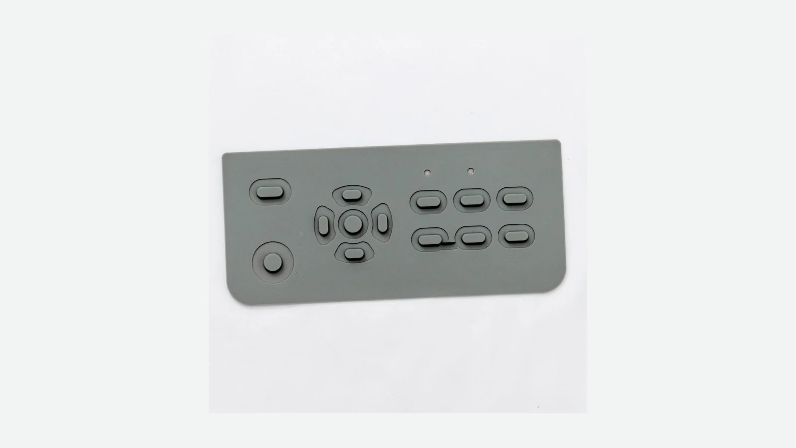
Silicone rubber moves, stretches, and changes response with geometry and support. A sample can match its color chip and still bind in the bezel, miss a PCB pad, feel different after assembly, or return too weakly. This guide defines the evidence needed to approve, hold, or reject a rubber keypad first article. It does not replace finished-HMI reliability, safety, ingress, EMC, usability, or regulatory validation.
Why a Visually Good Keypad Sample Can Still Fail
A molded keypad is one element in a mechanical and electrical stack. The user presses the keytop; the web collapses; a conductive element approaches the PCB; the housing and PCB support the load; the electronics decide whether a valid input occurred. Change one interface and the same loose keypad can behave differently.
Finger / actuator load
Keytop and legend surface
Silicone web (force, travel, snap, return)
Carbon pill / conductive contact / external switch actuator
PCB pad geometry, finish and electrical threshold
PCB support, hard stop, housing, gasket and fasteners
This is why silicone rubber keypad construction options should be reviewed with the mating PCB and enclosure rather than in isolation. A fingertip check can find a jammed key. It cannot establish a repeatable force-displacement curve, contact margin, lighting uniformity, coating durability, or revision baseline.
The predictable failure chain is short:
- The buyer approves an attractive loose sample.
- The production drawing still has open datums, force conditions, contact geometry, or visual limits.
- The installed part adds preload, uneven support, bezel friction, or a different hard stop.
- A later lot matches the incomplete drawing but not the engineer’s memory of the sample.
- The dispute becomes subjective because no curve, measurement condition, approved assembly, or deviation record defines “same.”
First-article principles prevent that outcome by linking characteristics to the part, process, and evidence. SAE International’s AS9102C formalizes this concept for aerospace first-article inspection. It is not automatically required for a commercial silicone keypad, yet the underlying discipline is useful: identify the design requirements, record objective results, resolve discrepancies, and preserve the approved baseline.
Define the Approval Baseline Before Inspecting the Sample
A silicone keypad sample has no stable approval meaning until its identity and test conditions are fixed. Before measurement, the reviewer should place the sample beside the active 2D drawing, 3D model, artwork, material/coating specification, PCB contact drawing, enclosure revision, bill of materials, and supplier report. Each file needs a revision. Each physical unit needs a sample or cavity identifier.
The keypad prototyping process should also state what the sample represents. A soft-tool appearance model may answer color and fit questions while remaining unsuitable for force or life decisions. A production-tool sample molded with the intended material, cure, contact, printing, coating, and downstream operations can support a much broader release. Mixing those stages creates false confidence.
Use four baseline labels:
| Label | Meaning | Approval use |
|---|---|---|
| Appearance model | Representative shape, color, legends, or finish; process may differ from production | Ergonomics and visual direction only |
| Engineering prototype | Functional sample built to investigate geometry, contact, force, light, or assembly | Close named technical questions; do not imply full production release |
| Production-intent first article | Intended tool, material, cure, contacts, graphics, coating, and operations | Candidate for dimensional, functional, visual and assembly approval |
| Approved production baseline | Identified sample plus released files, results, deviations and signatures | Reference for repeat production and controlled change |
A valid inspection header records the part number, part revision, drawing revision, artwork revision, tool and cavity if relevant, sample ID, quantity, material identity, molding/post-cure state, coating state, conditioning, test date, equipment or fixture ID, inspector, and decision owner. JASPER’s documented inspection and traceability workflow uses the same logic: a result is useful only when it points to the active requirement and the item tested.
Baseline record checklist
| Record field | What to capture | Why it matters |
|---|---|---|
| Product identity | Part number, sample ID, quantity and cavity | Keeps unit-level results traceable |
| Design identity | 2D, 3D, artwork, PCB and enclosure revisions | Prevents cross-revision approval |
| Build identity | Tool, material, contact, pigment, coating and process state | Defines the construction actually tested |
| Test identity | Date, condition, fixture, equipment, operator and method | Makes later correlation possible |
| Authority | Open deviations, reviewer, decision and date | Separates technical evidence from release authority |
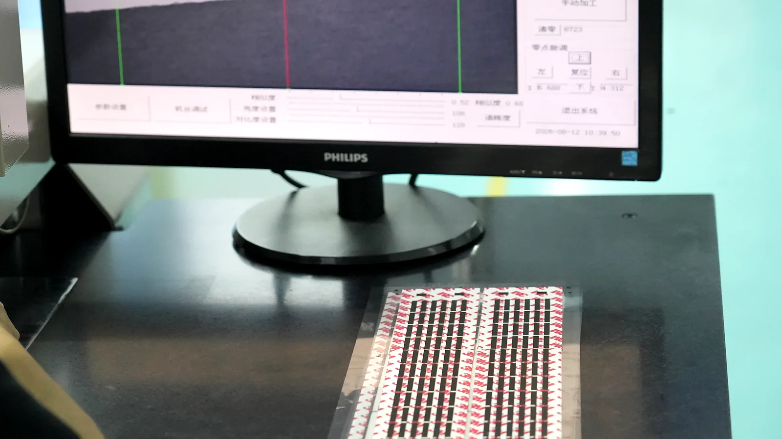
The 10-Gate Silicone Keypad Sample Approval Checklist
The ten gates below follow the order in which an OEM team should remove ambiguity. A failure at an early gate can invalidate later measurements. If the sample revision is uncertain, for example, a perfect force curve has no controlled product to release.
Gate 1 — Confirm Revision and Sample Identity
Start by proving that the sample and the reviewed documents describe the same build. Match part number, revision, artwork, material, color, contact option, coating, tool revision and cavity. Confirm whether rework occurred. If the supplier changed web geometry after the drawing was issued, the revised geometry must be documented before approval.
Every unit has a sample ID; every report names that ID; active files share the correct revisions; deviations are listed rather than hidden in email.
The approval request says “latest sample,” but the bag, drawing and report cannot be correlated. Another warning is a hand-modified key, trimmed flash or local coating repair that is not marked as rework.
The output from Gate 1 is an as-built configuration record. It prevents approval of one geometry while production follows another.
Gate 2 — Inspect Dimensions Against Functional Datums
Measure the geometry that controls the PCB and enclosure interface: overall outline, key centers, keytop width and height, base thickness, contact diameter and position, mounting holes, pull-throughs, sealing ribs, vents, web clearance and datum relationships. Do not copy a machined-metal tolerance scheme onto a broad elastic molding. Silicone can distort under its own weight, clamping force or an aggressive probe.
Diamond HMI and Epec both publish molded-keypad tolerance examples that widen as dimensions increase. Their tables demonstrate a design reality, not a universal acceptance rule. The project drawing must state the actual limits, datum scheme, measurement support, free-state or restrained condition, and measuring method.
| Dimensional question | Record on the report | Do not assume |
|---|---|---|
| Overall size and key pitch | Datum, support state and individual results in mm | A flexible array behaves like a rigid machined plate |
| Contact position | X/Y location, diameter, cavity and PCB-pad relationship | Nominal overlap proves worst-case margin |
| Height and travel stack | Base, keytop, bezel, stop and travel dimensions in mm | A correct loose height guarantees installed clearance |
| Mounting and sealing features | Hole/rib location, restraint and assembly reference | Pull-throughs or ribs can be stretched flat for measurement |
Critical-to-function dimensions are ballooned; the report gives nominal, tolerance, result, method and sample ID; the part is supported without stretching.
The inspector measures only overall length and width, rounds every result to one decimal place, or forces a soft part flat without defining the restrained condition.
For an array, look at accumulated position error. Ten individually acceptable key pitches can still place the final key too close to its bezel opening if the datum strategy is wrong.
Gate 3 — Approve the Full Force–Displacement and Return Curve
Key feel is a curve, not one number. Record press force versus displacement through web collapse and electrical contact, then record the release path. The curve reveals peak actuation force, contact force, travel, snap, hysteresis, return force, double peaks and friction. Test the key on a representative support at a defined speed, orientation, temperature and conditioning state.
A common snap-ratio definition is:
Snap ratio = (F1 − F2) / F1 × 100%
Here, F1 is peak actuation force and F2 is the lower force after collapse or contact. Use 125-150 gf (about 1.23-1.47 N) actuation with 40-60% snap as a starting comparison, together with 30-35 gf (about 0.29-0.34 N) return guidance. These values organize the first sample matrix; final pass/fail limits come from the project specification and installed user evaluation.
The report includes press and release traces for representative keys and positions, units, speed, fixture, support, conditioning and acceptance bands.
Approval depends on “feels good,” a handheld force gauge with no travel record, or one center key even though wide and tall keys use different geometry.
| Curve characteristic | Symbol / unit | Approval question |
|---|---|---|
| Peak actuation force | F1, N or gf | Is the peak inside the project band at the specified speed and support? |
| Post-collapse/contact force | F2, N or gf | Is contact achieved with adequate mechanical and electrical margin? |
| Snap ratio | (F1 − F2) / F1 × 100% | Does tactile drop meet the agreed user and life tradeoff? |
| Travel | mm | Do peak, contact and hard stop occur in the intended sequence? |
| Return force | N or gf | Does the key recover without sticking in the installed stack? |
A high snap ratio is not automatically better. Diamond HMI’s a tradeoff between tactile response and life; higher durometer, higher force or longer stroke can also reduce life when other factors stay equal. The best curve is the one the user and application require, with enough return margin after assembly and environmental exposure.
Gate 4 — Correlate Mechanical Travel with Electrical Contact
A key can collapse without producing a reliable electrical input. The sample review must connect conductive-pill geometry, PCB pad pattern, overlap, alignment, contact load, closure threshold and electronics. Define whether the measured characteristic is contact resistance, circuit closure, voltage threshold, debounce response or another system value.
Test at the specified load and at more than one point when off-center pressing is credible. Record the PCB revision and surface condition. Contamination, flux residue, dust, oil and condensation can matter as much as nominal contact geometry.
Mechanical contact position appears on the force curve; electrical closure is recorded on the same sample and representative PCB; the pad has alignment margin at tolerance extremes.
A continuity beep on a loose keypad is treated as proof of installed performance, or the report gives a resistance value without load, pad, equipment, stabilization time or sample identity.
The decision boundary matters. The keypad supplier can measure agreed component behavior. The OEM owns the electronics threshold, firmware debounce, ghosting logic, system fault handling and finished-device acceptance unless the contract assigns those tasks elsewhere.
Gate 5 — Approve Legends, Color and Cosmetic Boundaries
Visual approval needs controlled references. Identify the master artwork revision, font, line weight, symbol orientation, print or molded-color process, color target, texture, gloss, cosmetic zones, viewing distance and lighting. A Pantone, RAL or physical master can define direction, but the acceptance method must account for the selected material and process.
Inspect every legend for registration to the keytop and for distortion over curved surfaces. Check positive and negative graphics, icon fill, edges, pinholes, contamination, color bleed and exposed base material. For molded color, confirm boundaries and gates. For laser-marked keys, verify that the removed coating creates the intended shape and light path.
Reviewer and supplier use the same physical or instrumented reference under named illumination, with acceptable and reject examples for critical defects.
Approval occurs from an email screenshot or phone photograph with automatic white balance. “Match the brand blue” is not an inspection instruction.
Cosmetic zoning makes the decision more practical. A defect on a primary legend may be unacceptable while the same-sized mark on a hidden flange has no user consequence. Put those zones on the drawing rather than negotiating them after tooling.
Gate 6 — Separate Coating Appearance from Coating Qualification
A clear or pigmented coating can improve surface feel, protect printed legends, control gloss, or support laser etching. A pristine first sample proves only its initial state. It does not establish abrasion life, chemical resistance, UV resistance, adhesion after aging, or suitability for cleaning agents.
Record the coating system, color layers, coverage area, thickness or process control where applicable, cure/post-cure state, masking, overspray limits and approved tactile/visual reference. Then define tests from the actual exposure: repeated finger contact, specified cleaners, oils, sunscreen, disinfectants, outdoor light, humidity or temperature. Do not add all tests by habit; select the ones tied to the use environment.
The approval package distinguishes initial appearance from qualification evidence and names the coating-related change triggers.
A supplier calls a coating “wear resistant” without a test method, load, counter, endpoint or sample construction. Another release blocker is approving an epoxy keytop for outdoor use solely because it appears hard; Diamond HMI’s coating guidance specifically cautions that its epoxy option is not recommended outdoors because of UV limitations.
Coating is also not always the best construction. For high-abrasion illuminated legends, a molded translucent keypad with controlled paint and laser etching may fit better. For simple, non-illuminated indoor controls, molded color or protected print may avoid unnecessary process steps. The usage profile decides.
Gate 7 — Evaluate Lighting in the Intended Optical Stack
Backlit keys must be judged with the intended light source, drive current, LED bin or color, PCB spacing, reflector, light guide, masking, coating stack and housing. Inspect in powered and unpowered states. Include normal viewing angles, a dark condition, the actual ambient condition and any camera-independent visual limit.
Look for bright spots, dim legends, edge leakage, color mismatch, blocked symbols, uneven stroke width and light transfer between adjacent keys. A lux or luminance method can help when the project requires numerical uniformity, but the measurement geometry and points must be specified.
The approval fixture reproduces the PCB and enclosure optical stack; photographs lock exposure only as supporting evidence; numerical readings identify locations and conditions.
A loose translucent keypad is held over a flashlight, or a phone camera’s exposure algorithm decides uniformity.
Lighting may be irrelevant. An opaque, non-illuminated industrial keypad should not inherit a backlight gate merely to make the checklist look complete. Mark the gate not applicable, name the reason, and retain that decision in the record.
Gate 8 — Verify PCB, Enclosure, Hard Stops and Assembly Fit
Assembly fit is the point at which separate acceptable parts become one acceptable interface. Install the production-intent keypad, PCB, bezel, gasket, fasteners, backer and any adhesive. Use the intended torque or retention method. Check key centering, free movement, preload, rocking, return, bezel rub, venting, sealing compression, hard-stop clearance and PCB deflection.
JASPER’s anonymous silicone keypad control-interface case documents this boundary with a real retained sample while deliberately withholding customer and performance claims. Its key lesson is transferable: force, contact, graphics, PCB and enclosure evidence must close as one interface.
The same identified units have loose-part curves and installed checks; the assembly drawing defines support and hard stops; edge and corner keys are exercised.
The keypad passes on a steel plate but the actual PCB flexes, or the bezel adds side load that slows return. A housing CAD overlay alone cannot reveal friction, compression or stack-up behavior.
If the enclosure is unavailable, do not issue full approval. A conditional hold can release tooling correction or another prototype build while listing assembly fit as an open gate.
Gate 9 — Review Workmanship, Contamination and Packaging
Inspect more than the best sample. Review all submitted units and, for multi-cavity tooling, each represented cavity. Define short shots, tears, web damage, flash, knit or flow marks, trapped particles, pigment contamination, conductive-material contamination, coating defects, print defects, deformation and odor only where the project can evaluate them objectively.
Packaging belongs in this gate because a compliant keypad can arrive distorted, dusty or abraded. Define orientation, layer separation, bag material, part count, label, lot identity and protection from compression or migration. If a post-cure or cleaning state matters, record it before sealing the package.
The report shows sample distribution rather than one “golden” part, uses a defect catalog, links defects to cavities/lots and demonstrates the proposed production pack.
Samples arrive stacked under load, conductive surfaces touch printed or coated faces, or the supplier selects one flawless unit while withholding the range.
Aesthetic variation is not automatically a functional defect. The drawing should separate critical, major and minor conditions based on use, not by how easy each feature is to inspect.
Gate 10 — Release the Evidence Package and Reapproval Triggers
Approval is complete only when another engineer can reconstruct what was accepted. The package should contain the active drawing and artwork, ballooned dimensional report, force-displacement curves, electrical results, visual references, lighting results if applicable, installed-fit record, material/contact/coating identity, sample photos, deviations, disposition, approved physical sample or retention plan, and signatures with dates.
Then define change triggers. Material, pigment, contact pill, coating, artwork, tool repair, cavity, molding or post-cure process, PCB pad, enclosure support, inspection method and packaging may affect the baseline. JASPER’s documented engineering change control method links a proposal to impact, evidence, approval, effective lot/date and old/new segregation.
The release says what changes require notification, new samples, partial reinspection, installed checks or full reapproval.
The signature approves “sample OK” but leaves no objective results, or the manufacturer can substitute a commercially similar material without the agreed impact review.
The physical approved sample is useful, but it does not outrank the drawing. Silicone ages, colors shift, and reference parts can be lost. Define precedence among specification, drawing, artwork, numerical results and master sample before a conflict occurs.
Keypad Quality Inspection Matrix and Decision Rules
A good keypad quality inspection matrix names the question, condition, record and owner. It does not assign every characteristic the same sample size or pretend that supplier inspection closes OEM system validation. The testing and validation planning page can support a project-specific plan.
| Inspection block | Minimum condition to record | Evidence | Decision owner |
|---|---|---|---|
| Identity | Part/sample ID, file revisions, tool/cavity, material and process state | Configuration sheet and labeled samples | Buyer engineering + supplier quality |
| Dimensions | Datum, free/restrained state, support, instrument, resolution, conditioning | Ballooned report with individual results | Mechanical engineering |
| Force and return | Key position, fixture/support, speed, temperature, cycles/preconditioning | Press/release curves and calculated characteristics | HMI/mechanical engineering |
| Electrical contact | PCB revision, pad state, load/travel, instrument, threshold and repeated points | Closure/resistance trace or table | Electrical engineering |
| Legends/color | Artwork, color master, illumination, viewing geometry and cosmetic zones | Controlled photos plus visual/instrument record | Industrial design + quality |
| Coating | System, cure, coverage, appearance and use-specific qualification plan | Initial inspection and separate qualification report | Materials/quality engineering |
| Lighting | LED/source, drive, stack, ambient/dark state, angle and points | Powered images and readings where specified | Optical/HMI engineering |
| Assembly fit | PCB, housing, gasket, fasteners, torque, support and hard stops | Installed checklist, photos and functional result | Product engineering |
| Workmanship/pack | Sample distribution, cavity, defect catalog, packing configuration | Unit-level defect log and pack review | Supplier and incoming quality |
| Release/change | Open deviations, precedence, signatures, effective revision and triggers | Signed approval package | Named product authority |
Use three decision states:
| State | Entry criterion | Required record | Production effect |
|---|---|---|---|
| PASS | All applicable gates meet released requirements | Signed results, closed deviations and baseline identity | Release may proceed within the approved scope |
| HOLD | Evidence or representative hardware is missing | Owner, open question, action and due evidence | No final production release |
| REJECT | A released requirement is not met or identity is unreliable | Nonconformance, containment and reinspection scope | Corrective action and new evidence required |
- PASS: All applicable gates meet released requirements; deviations are closed; the approved baseline and change rules are identified.
- HOLD: Evidence is missing or an interface cannot yet be evaluated, but no confirmed nonconformance requires rejection. List owner, action and due evidence. Do not quietly convert HOLD to approval because tooling or schedule is urgent.
- REJECT: A released requirement is not met, the sample identity is unreliable, or a defect invalidates downstream evaluation. Record containment and whether corrected first articles require full or partial reinspection.
A concession can release a known nonconformance for a defined scope. It should name the affected sample or lot, reason, risk owner, expiration and whether the drawing will change. A concession is not evidence that the characteristic met the original requirement.
Five-Step Rubber Keypad First-Article Process
Step 1 — Freeze the Review Package
Release the drawing, 3D model, artwork, PCB pads, enclosure interfaces, material/contact/coating requirements and applicable acceptance methods. Mark conflicts and precedence. Identify critical characteristics and which gates are not applicable. The supplier should return a build-state summary before shipping samples.
Step 2 — Receive and Quarantine Identified Samples
Log quantity, IDs, cavity, packaging and visible condition. Do not mix first articles with earlier prototypes. Photograph labels and units for traceability, not as a substitute for inspection. If shipment damage or distortion could affect results, record it before conditioning or assembly.
Step 3 — Measure Loose-Part Characteristics Under Controlled Conditions
Complete identity, dimensions, force-displacement, return, contact geometry, workmanship, legends and coating appearance. Run electrical contact checks on the specified representative PCB where possible. Keep raw results by unit and key position; averages alone can hide edge-key or cavity failures.
Step 4 — Correlate the Installed Assembly
Install selected samples in the intended PCB and enclosure stack. Repeat critical feel, return, electrical, light and interference checks. Evaluate tolerance extremes where practical. If final hardware does not exist, document the surrogate fixture and leave the true assembly gate open.
Step 5 — Close Deviations and Issue the Baseline
Classify every open item as pass, hold, reject, approved concession or planned engineering change. Update drawings where the accepted construction differs from the release package. Sign the report, identify retained masters, define the effective production revision and list reapproval triggers. This turns the rubber keypad first article into production evidence rather than a box of samples.
Project Inputs for a Silicone Keypad Prototype Checklist
Before asking a supplier to prepare samples, assemble these inputs:
- [ ] Part number, active 2D/3D revisions and drawing precedence
- [ ] Key map, datums, critical dimensions, travel and hard-stop relationship
- [ ] PCB pad pattern, finish, support, electrical threshold and test method
- [ ] Enclosure, bezel, gasket, fasteners, stack-up and installation method
- [ ] Material family, durometer target if specified, color and post-cure requirements
- [ ] Conductive contact type, geometry, position and acceptance method
- [ ] Artwork, color reference, print/laser process, coating and cosmetic zones
- [ ] Lighting source, drive, mask, viewing state and optical criteria if applicable
- [ ] Use environment and the exact wear, cleaner, chemical, UV or temperature exposures that matter
- [ ] Sample stages, quantities, cavity coverage, reports, retained samples and approval owners
- [ ] Packaging, labeling, traceability, deviations and engineering-change rules
This silicone keypad prototype checklist should travel with the request, not appear after the first samples arrive. It gives the manufacturer enough context to design measurable evidence and helps the OEM distinguish a DFM question from an approval criterion.
When This Checklist Is Not Enough
This framework approves a component baseline only within the evidence actually reviewed. It is not enough when the keypad’s failure could create a safety, regulatory or mission-critical system risk; when ingress depends on the full enclosure; when chemical or cleaning exposure is severe; when tactile response must remain stable after aging; or when optical uniformity depends on final electronics and housing.
In those cases, add project-specific qualification and system validation. That may include environmental cycling, defined chemical exposure, wear testing, accelerated or repeated actuation, sealing tests, EMC/ESD evaluation, usability studies, software fault handling, or regulated-device documentation. The legal manufacturer decides which standards and evidence apply.
A silicone keypad is also not always the best construction. Choose discrete mechanical switches when sharply defined switch ratings, individual replacement or very short travel dominate. Choose a membrane switch when a thin sealed graphic interface and low profile matter more than molded key travel. Choose capacitive touch when a continuous, cleanable surface and no mechanical travel fit the user and environment. The sample checklist cannot cure a construction that conflicts with the application.
| Application constraint | Better candidate | Decision boundary |
|---|---|---|
| Rated discrete switch behavior and service replacement | Mechanical switch | Compare switch rating, mounting, ingress strategy and user force |
| Very thin sealed graphic panel | Membrane switch | Validate dome/circuit/overlay stack rather than molded web behavior |
| Continuous surface with no travel | Capacitive touch | Validate glove, water, EMC, grounding and firmware behavior |
| Sculpted keys, quiet travel and integrated sealing | Silicone rubber keypad | Run the ten-gate component and installed-interface review |
Frequently Asked Questions
What does silicone keypad sample approval actually approve?
It approves an identified production-intent construction against released, project-specific requirements and records. A complete approval links the physical sample to dimensions, force/return curves, electrical contact, graphics, coating, lighting, installed fit, workmanship, deviations and revision evidence. It does not automatically approve the finished device.
Is a rubber keypad first article the same as a prototype?
No. A prototype may investigate appearance, fit or one engineering question using non-production materials or processes. A rubber keypad first article intended for production release should represent the planned tool, material, cure, contacts, graphics, coating and operations, with objective results tied to active revisions.
What actuation force and snap ratio should a silicone keypad use?
There is no universal value. Diamond HMI publishes 125–150 gf (about 1.23–1.47 N) and 40–60% snap as common starting guidance, but key size, stroke, durometer, support, user, environment and life target can shift the choice. Approve the full installed force–displacement curve, not the benchmark alone.
How is silicone keypad snap ratio calculated?
A common formula is (F1 − F2) / F1 × 100%, where F1 is peak actuation force and F2 is the lower force after web collapse/contact. Supplier labels can differ, so the report should define each point and include the underlying press and release curves.
Should keypad quality inspection test every key on every sample?
Not by default. The plan should cover functional risk: representative center, edge, corner, wide, tall, illuminated and critical keys; each cavity where relevant; and enough units to expose variation. Safety-critical or contract-defined characteristics may require broader coverage. Record the actual sampling rather than implying 100% inspection.
Can a loose silicone keypad sample be approved without the PCB and housing?
Only conditionally. Loose-part approval can close appearance, selected dimensions and fixture-based force questions. Final contact, return, friction, hard-stop, preload, lighting and user feel depend on the PCB and housing stack. Keep assembly fit on HOLD until representative hardware is available.
What should be included in a silicone keypad prototype checklist?
Include active drawings and artwork, PCB pads, enclosure stack, datums, force/travel targets, contact method, graphics, coating, lighting, use environment, sample stage, test conditions, reports, packaging, deviations and named approval owners. State which questions the prototype can and cannot answer.
When should a keypad sample be reapproved?
Reapproval should follow the agreed change rules. Common triggers include material or pigment changes, contact changes, artwork or coating changes, tool repair or cavity change, molding/post-cure changes, PCB pad or enclosure changes, a revised inspection method, and any corrective action that alters the released interface.
Plan the Keypad Sample Acceptance Review
Start with one table: requirement, method, condition, sample coverage, evidence and approval owner. Send it with the drawing, PCB pad map, enclosure stack, artwork and intended sample stage. Then use the ten gates to decide which results can close on a loose part and which must wait for the assembled HMI.
Send the requirement table, drawings, PCB pad map, enclosure stack, artwork, and intended sample stage through the engineering review route. Use the ten gates to decide which results can close on a loose part and which require the assembled HMI.
Technical References
- Source: SAE AS9102C First Article Inspection Requirement. Accessed 2026.
- Source: Diamond HMI Rubber Keypad Design Guide 2021. Accessed 2026.
- Source: Epec Silicone Rubber Keypad Design Guidance. Accessed 2026.
- Source: N&H Technology Silicone Rubber Keypad Design Guide. Accessed 2026.
- Source: Mekoprint Silicone Rubber Keypad Design Guide. Accessed 2026.
- Source: Diamond HMI. Accessed 2026.
- Source: Epec. Accessed 2026.
- Source: 2021 guide. Accessed 2026.
- Source: coating guidance. Accessed 2026.
- Source: AS9102C: Aerospace Series — First Article Inspection Requirement. Accessed 2026.
- Source: Rubber Keypad Design Guide 2021. Accessed 2026.
- Source: Silicone Rubber Keypad Design — Specifications and Physical Properties. Accessed 2026.
- Source: Design Guide: Silicone Rubber Keypads. Accessed 2026.
- Source: Design Guide for Silicone Rubber Keypads. Accessed 2026.
Review the complete keypad stack before release
Send the keypad drawing, contact geometry, PCB artwork, environment, appearance targets, and validation plan for a project-specific review.