
Recording vs stimulation electrodes differ in signal direction, area, materials, connectors, electronics, tests, and finished-device validation.
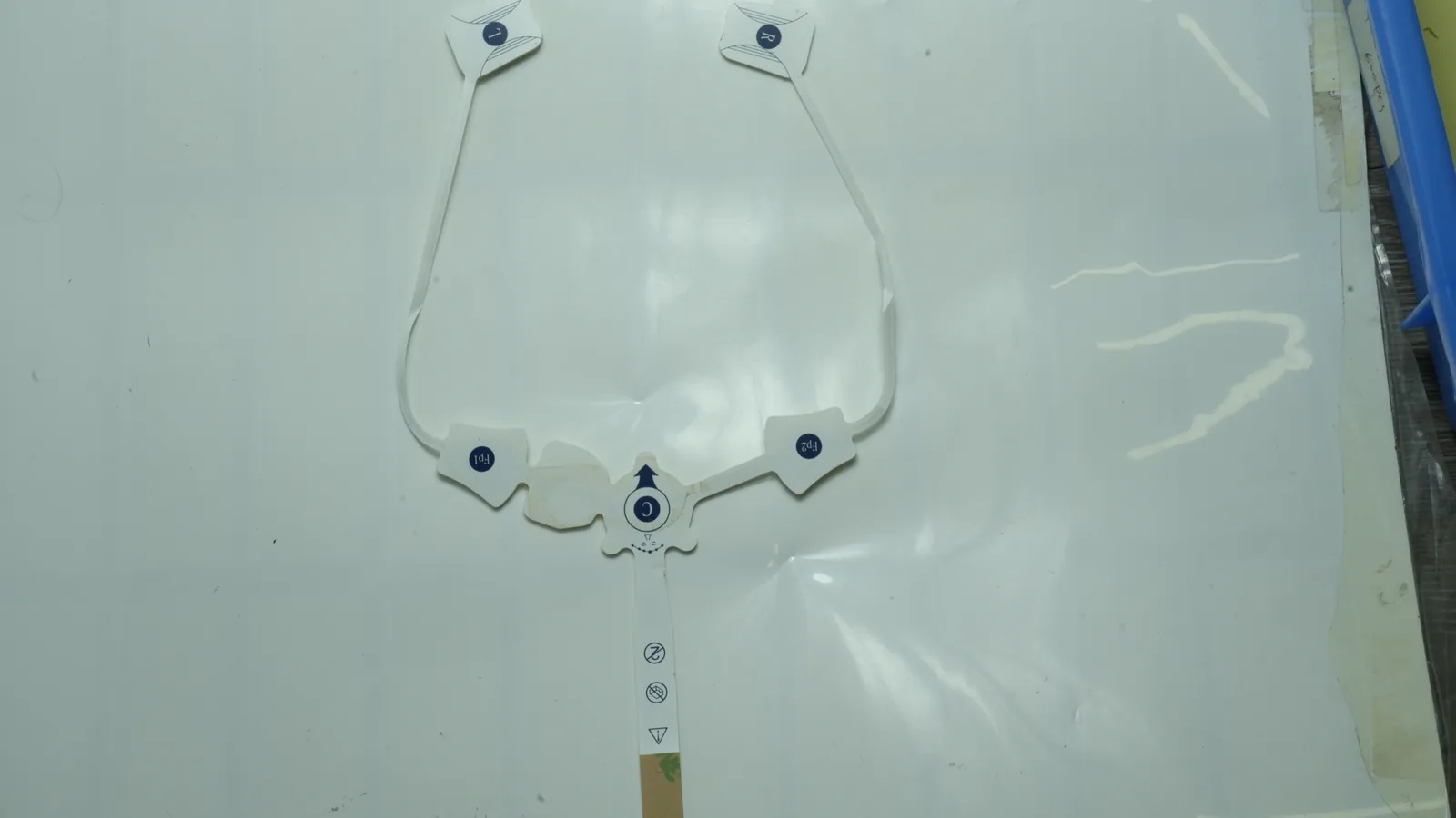
JASPER certifications: ISO 9001, ISO 13485, IATF 16949, and ISO 14001.
Scope boundary: This engineering comparison covers noninvasive, skin-contact printed electrode pads. It does not give treatment instructions, electrode-placement advice, patient-safety limits, or regulatory approval conclusions. Implantable-electrode literature is cited only for electrode-interface principles that also require project-specific verification at the skin.
1. Quick Verdict: Decide What Crosses the Interface
The practical verdict is simple. Choose a biopotential recording electrode when the system must preserve a small signal for ECG/EKG, surface EMG, or surface EEG acquisition. Choose an electrical stimulation electrode when the system must distribute a specified waveform for a TENS, EMS, or NMES device. If one physical electrode must do both, treat that as a third architecture—not as a free combination of the first two.
| Engineering priority | Recording electrode | Stimulation electrode | Dual-function architecture |
|---|---|---|---|
| Primary transfer | Tissue potential into a high-input-impedance front end | Generator current into the electrode–skin interface | Alternates between both directions under controlled switching |
| First electrical concern | Signal fidelity, interface impedance, channel mismatch, noise | Charge per phase, polarization, active area, current distribution | Artifact, recovery time, residual polarization, isolation |
| Geometry emphasis | Repeatable contact and matched sensing sites | Adequate exposed area and controlled edge/current distribution | Must satisfy both; often adds area, routing, or switching constraints |
| Typical interface candidate | Ag/AgCl with a defined electrolyte/contact medium | Carbon, conductive polymer/rubber, metal/Ag-based conductor, or another qualified current-spreading stack | One qualified multifunction interface or physically separate active regions |
| Electronics dependency | Amplifier input, bias path, common-mode control, bandwidth | Current/voltage compliance, pulse timing, phase balance, fault control | Front-end protection, blanking, switching, synchronization, recovery |
| Best default | Optimize for acquisition only | Optimize for delivery only | Use only when system-level benefit justifies coupled verification |
No column “wins” universally. Recording construction is not the best choice when it cannot carry the intended stimulation waveform without unacceptable polarization or current concentration. A large stimulation pad is not the best choice when spatial selectivity, array density, or a compact recording site controls the design. Separate electrodes are usually easier to specify when simultaneous operation, rapid recovery, or independent replacement matters.
2. Two Electrical Jobs, Two Energy Paths
A skin electrode is an electrochemical and mechanical interface among electronic conductors, an ionic contact medium, skin, and the equipment. Stuart Cogan’s 2008 review in the Annual Review of Biomedical Engineering models it with a half-cell potential, double-layer capacitance, charge-transfer resistance, and series/solution resistance. Values vary with frequency, material, area, electrolyte, skin preparation, pressure, hydration, time, and manufacturing history (Cogan, 2008).
Recording path: body signal to converter
Biopotential source in tissue
ionic conduction
Skin + electrolyte/contact medium
electrode–electrolyte transduction
Exposed recording interface
electronic conduction
Printed trace → connector → protected analog front end
amplification / filtering / conversion
Recorded ECG, EMG, or EEG data
The recording channel receives rather than drives. Its interface should not add enough offset, noise, drift, impedance imbalance, motion artifact, or environmental pickup to obscure the signal of interest. Stephen Lee and John Kruse’s Analog Devices review places electrode behavior inside the full ECG/EEG/EMG acquisition chain rather than treating the pad as an isolated resistor (Analog Devices). That systems view matters: an impedance value without frequency, electrode pairing, amplifier input characteristics, and test fixture is incomplete.
Stimulation path: generator to tissue and back
Controlled waveform generator
lead / connector / printed trace
Current-spreading conductor
exposed stimulation interface
Electrolyte/contact medium + skin
intended current path through tissue
Return electrode and return conductor
monitored output stage
Generator
The stimulation channel drives energy through a complete circuit. Current amplitude alone does not characterize that transfer. The device team must define pulse shape, pulse width, frequency, duty cycle, phase sequence, maximum compliance voltage, active area, return path, fault cases, and the state of the interface over use and aging. Merrill, Bikson, and Jefferys explain why waveform and charge balance matter in neural stimulation, while also showing that electrochemical response depends on the electrode system rather than one universal number (Merrill et al., 2005).
A useful model, not a complete simulation
Electronic conductor · interface impedance Z(f) · electrolyte/skin
half-cell potential
double-layer capacitance
charge-transfer resistance
For recording, Z(f) affects noise, attenuation, mismatch, and common-mode conversion in the acquisition band. For stimulation, the same interface experiences driven current and time-varying polarization. The model is useful for requirements and test fixtures, but it does not predict local skin current distribution, adhesive lift, gel dehydration, or edge effects by itself.
3. Recording vs Stimulation Electrodes: Side-by-Side Design Matrix
The central electrode pad design difference is the electrical envelope imposed on the same physical stack. Every drawing should connect geometry and materials to that envelope.
| Design dimension | Biopotential recording electrode | Electrical stimulation electrode | Specification consequence |
|---|---|---|---|
| Controlled input | Expected signal type and acquisition bandwidth | Maximum programmed and fault waveform | Put signal/waveform assumptions in the system requirement, not only the pad drawing |
| Active area | Sized for contact repeatability, spatial resolution, placement envelope, and channel layout | Sized with current/charge distribution and return path in mind | Dimension the exposed area separately from the external pad outline |
| Interface metric | Complex impedance versus frequency, electrode-pair mismatch, offset/drift, noise | Voltage transient, polarization, impedance under pulse, current distribution, charge per phase | One DC resistance value cannot approve either design |
| Material role | Stable ionic-to-electronic transduction; Ag/AgCl is a common candidate under controlled chloride/electrolyte conditions | Qualified current-spreading and charge-transfer behavior; carbon, conductive rubber/polymer, or metallic systems may be candidates | Identify the exact ink/material and cure, not only “silver” or “carbon” |
| Trace design | Low and repeatable series resistance; guarded/shielded routing may matter to the electronics | Current capacity, voltage spacing, insulation, return routing, and connector heating matter | Define conductor width, dielectric overlap, keep-outs, and termination |
| Contact medium | Wet gel, hydrogel, or dry interface selected for signal, motion, wear, and packaging requirements | Hydrogel or another qualified medium selected for waveform transfer, adhesion, and use sequence | Formulation and thickness are controlled inputs; “hydrogel” is not a complete specification |
| Connector | Channel identity, reference/ground scheme, touch protection, low-noise transition | Polarity/state control, current path, lead retention, output compatibility | Keying and pin assignment can prevent cross-connection |
| Electronics | High-input-impedance analog front end, bias/reference path, common-mode and ESD protection | Controlled output, compliance voltage, charge balancing, monitoring, shutdown | Pad approval must use the intended electronics or an equivalent controlled fixture |
| Typical standard context | ANSI/AAMI EC12 for disposable ECG electrodes; relevant IEC 60601 ECG equipment standards | IEC 60601-2-10 for nerve and muscle stimulators | Standards attach to a defined finished device/equipment scope, not to a generic print layer |
| Dominant integration failure | Noise, baseline shift, mismatch, motion artifact, intermittent contact | Local concentration, excessive polarization, open/partial contact, connector or output fault | Failure analysis must include pad, cable, electronics, user interface, and use condition |
Geometry must name the electrically active boundary
The external die-cut outline may include a handling tab, connector island, adhesive border, liner split, and strain-relief region. None of those necessarily equals active area. The drawing should hatch or otherwise identify the exposed conductive/contact region and give its area. For a stimulation concept, current divided by nominal exposed area provides an early geometric current-density calculation, but Cogan and Merrill show why this cannot be treated as a local distribution or safety conclusion. Edge shape, lift, wrinkles, gel thickness, anatomical contour, and return placement can make the interface nonuniform.
4. Where Recording-Electrode Design Takes Priority
Recording design takes priority when the wanted output is a faithful representation of body-generated potential over a defined bandwidth. The electrode, cable, front end, mechanics, and algorithm form one acquisition chain.
Control impedance as a spectrum and a pair
A single resistance measurement can catch an open trace, but it does not characterize a skin-contact recording interface. The requirement should state frequency or frequency sweep, excitation method, fixture/electrolyte or skin model, stabilization time, temperature, electrode pairing, and whether the criterion concerns absolute impedance or mismatch. This is especially important for ECG/EKG electrode patches, where lead pairs and common-mode behavior affect acquisition.
ANSI/AAMI EC12 addresses disposable electrodes used for diagnostic electrocardiography and includes electrical performance methods. It does not make an Ag/AgCl print, hydrogel roll, or converted patch conforming by material name. FDA’s ECG electrode special-controls guidance also separates electrical performance, adhesive performance, biological evaluation, shelf life, and labeling as finished-device evidence topics (FDA ECG electrode guidance).
Treat motion as an electrical input
Cable tug, substrate bending, gel shear, and adhesive lift can change contact conditions and create a signal inside the acquisition band. A lower bench impedance measured in a static saline fixture does not guarantee lower motion artifact on the intended body location. Recording sample approval should therefore pair electrical tests with controlled bend, lead movement, dwell, humidity, temperature, and aging conditions selected by the device team.
Keep the front end in the requirement loop
Input impedance, input bias path, protection components, driven-reference strategy, cable shielding, sampling, filtering, saturation limit, and recovery behavior determine whether an electrode is acceptable. A supplier can verify print continuity and a defined coupon or assembly impedance method. The legal manufacturer still owns system signal quality under the intended acquisition chain and use environment.
Recording-optimized Ag/AgCl is not automatically the best construction when the project needs repeated high-current stimulation, a dry reusable interface, high stretch, dense spatial mapping, or chemistry incompatible with the selected gel and process. Those cases require a fresh materials and architecture decision.
5. Where Stimulation-Electrode Design Takes Priority
Stimulation design takes priority when current delivery—not passive acquisition—is the primary job. The pad must be considered with the generator, cable, return path, waveform, body interface, and foreseeable contact faults.
Specify charge and polarization, not a marketing current rating
For a rectangular phase, nominal charge per phase is current multiplied by phase duration. That number becomes meaningful only with the exposed area, material, interface condition, polarity sequence, interphase interval, repetition rate, duty cycle, and voltage transient. Reversible charge storage differs from irreversible faradaic processes, and charge-injection capability is material- and test-dependent. A generic “supports X mA” statement therefore cannot replace polarization and waveform evidence.
Nominally charge-balanced biphasic output can reduce net DC, yet the generator’s programmed balance does not prove zero residual electrode polarization. Component mismatch, coupling capacitors, switching, timing error, interface asymmetry, and partial contact can change the result. The system requirement should define what is measured, where it is measured, over how many pulses, and what recovery criterion applies.
Area and edge condition are functional dimensions
A stimulation electrode often uses a broader exposed region to spread current. Larger is not always better. Increased area can conflict with placement envelope, anatomical selectivity, adhesion over curvature, cable load, packaging, or the desired field. Rounded transitions, controlled dielectric overlap, uniform contact medium, and a defined return geometry may matter more than merely increasing the die-cut outline.
For TENS, EMS, and NMES electrode pads, the OEM should provide the maximum normal and fault waveforms, not just the device category. IEC 60601-2-10 covers particular requirements for nerve and muscle stimulators at the medical electrical equipment level. It does not certify an unconnected printed pad or substitute for the finished system’s risk controls, essential-performance analysis, and market-specific regulatory work (IEC 60601-2-10).
Design the return path at the same time
Current leaves through one interface and returns through another. If the return electrode, lead, connector, or contact condition differs, the pair may not share voltage or current stress equally. Draw both paths, define polarity or alternation, identify connector pins, and evaluate open, shorted, lifted-edge, partially attached, dried, folded, and wrong-pad conditions under the device risk process.
A broad stimulation construction is not the best choice when the main objective is low-noise recording, fine spatial discrimination, a dense multi-channel array, or rapid post-pulse acquisition. In those cases, separate sensing sites or a dual-region architecture may reduce compromise.
6. Material and Layer-Stack Choices Follow the Function
Material selection starts with the interface job, then proceeds through process compatibility. “Ag/AgCl,” “carbon,” “PET,” “TPU,” and “hydrogel” each describe a family. Ink ratio, binder, particle loading, dry-film thickness, cure history, surface treatment, dielectric overlap, gel chemistry, adhesive, liner, and aging state can change the result.
Recording-oriented printed stack
Release liner
Conductive electrolyte / hydrogel or qualified dry interface
Exposed Ag/AgCl or other qualified recording interface
Printed conductor trace under dielectric
PET, TPU, or other qualified substrate
Connector reinforcement / snap / tail termination
Backing, label, or carrier as required
Ag/AgCl is a common recording-interface candidate because the Ag/AgCl–chloride reaction can behave relatively nonpolarizably under suitable electrolyte conditions. That does not make every Ag/AgCl ink equivalent. DuPont 5874, for example, is a 65:35 Ag:AgCl composition specified for print-treated polyester; its data sheet describes a formulation and cure process, not a universal electrode property (DuPont 5874 technical data sheet). The selected interface still needs compatibility work with the conductor below it, gel above it, dielectric edge, connector process, packaging, and acquisition circuit.
A dry electrode may be preferable where gel dehydration, residue, packaging, or reuse dominates. It may also have different contact impedance, pressure dependence, motion sensitivity, and surface-wear behavior. The trade is real. “Dry” is an architecture branch, not an automatic upgrade.
For a source-backed recording-side planning point, Axelgaard's November 2022 AG625 sensing-gel TDS specifies 0.6 ± 0.1 mm thickness, maximum 600 Ω·cm volume resistivity, minimum 240 g/in skin-side peel on stainless steel, pH 3.5 ± 0.5, and bulk-roll shelf life of 12 months non-slit or 6 months slit (Axelgaard AG625 TDS). These are supplier-grade data, not JASPER results, skin-adhesion evidence, or finished-electrode shelf life.
Stimulation-oriented printed stack
Release liner
Qualified conductive contact medium
Exposed current-spreading interface
Low-resistance bus / printed conductor
Dielectric with controlled active-area opening
Dimensionally stable or extensible substrate
Lead wire, snap, tab, or tail with strain relief
Backing and skin adhesive zones as specified
Carbon, conductive rubber or polymer, silver-based conductors, and other material systems may support stimulation designs. Their roles should be separated. A low-resistance silver bus can carry current beneath dielectric while a different exposed layer controls the interface. Carbon may spread current or isolate another chemistry, but a carbon ink’s sheet resistance does not by itself state pulse polarization, gel compatibility, or local current distribution.
PET is often selected when dimensional registration and a stable printed circuit are primary. A stretchable TPU stack may fit motion and contour better, but the ink and dielectric must survive the specified strain and cure. Henkel ECI 1014 is one example of a stretchable silver ink; its existence does not prove compatibility with a different supplier’s TPU, dielectric, gel, or adhesive (Henkel ECI 1014).
For a stimulation-side planning point, Axelgaard's November 2022 AG735 TDS specifies 0.9 ± 0.1 mm thickness, maximum 1,500 Ω·cm volume resistivity, minimum 160 g/in skin-side peel on stainless steel, pH 4.2 ± 1.0, and bulk-roll shelf life of 18 months non-slit or 6 months slit. Axelgaard identifies AG735 as a stimulating gel designed for conductive film (AG735 product page; AG735 TDS). This is not a pulse-performance result, wear claim, or approved JASPER material.
| Layer decision | Recording question | Stimulation question | Do not assume |
|---|---|---|---|
| Exposed interface | What is its impedance, offset, drift, noise, and mismatch in the acquisition band? | What is its pulse polarization and charge-transfer behavior under normal and fault waveforms? | A material name predicts finished performance |
| Conductor | Does series resistance and routing preserve the signal and channel balance? | Can the bus, termination, and return path carry the specified output without unintended voltage drop or heating? | A continuity pass proves functional suitability |
| Dielectric | Does overlap prevent electrolyte contact with traces while avoiding unstable fringe geometry? | Does the opening define active area and survive repeated pulse/handling stress? | Nominal print artwork equals cured geometry |
| Contact medium | Does it support the signal, motion, dwell, and packaging requirements? | Does it support the specified pulse train and contact condition? | One hydrogel fits every body site and duration |
| Adhesive / backing | Does movement change the recorded baseline or channel contact? | Does edge lift or partial contact alter current distribution? | Peel strength equals clinical wear or comfort |
| Connector | Does it preserve channel identity and low-noise transition? | Does it control output path, polarity/state, retention, and fault handling? | Identical snaps make devices interchangeable |
ISO 10993-1:2025 frames biological evaluation within risk management for a device with direct or indirect body contact (ISO 10993-1). It is not a certificate attached to a raw ink or adhesive. The legal manufacturer must evaluate the finished contacting materials, processing residues, contact category and duration, packaging, aging, and other relevant evidence. ASTM D3330/D3330M-04(2025) can support a defined pressure-sensitive-adhesive peel comparison, but it does not demonstrate skin safety, clinical wear, or comfort (ASTM D3330).
7. Can One Pad Record and Stimulate?
One electrode can perform both functions, but “can” and “should” are different decisions. A 2026 Scientific Reports paper described a dry electrode tested for EMG recording and transcutaneous electrical stimulation. It established feasibility for that construction, not universal interchangeability (Scientific Reports, 2026).
A dual-function design must answer at least five extra questions:
- Operating state: Are recording and stimulation sequential, interleaved, or simultaneous?
- Switching: What protects and disconnects the sensitive acquisition front end during output pulses?
- Artifact: How much saturation occurs, and how long until the electrode plus electronics recover to the recording criterion?
- Polarization: What residual interface voltage remains after the pulse sequence, including component and contact mismatch?
- Fault containment: What happens if switching fails, one electrode lifts, a connector is reversed, or the wrong accessory is attached?
stimulation produces artifact on recording electrodes in its microelectrode context (NeuroNexus technical note). A surface-pad system has different geometry and tissue, yet the integration lesson holds: artifact and recovery must be measured in the intended signal chain.
Use separate electrodes when simultaneous operation, rapid post-pulse measurement, independent geometry, easier replacement, or clean verification boundaries outweigh package reduction. Use a dual-region electrode when shared placement is valuable but the recording and stimulation sites need different exposed materials or areas. A single shared active area is not the best choice merely because it reduces part count.
8. Follow the Failure Chain, Then Assign the Test
An electrode problem often appears one layer away from its cause. A lifted adhesive edge can change contact area; changed area can alter interface impedance or current distribution; the electronics may then report noise, saturation, compliance-limit operation, or a user-visible fault. Troubleshooting only the printed trace misses that chain.
| Observed failure | Plausible upstream cause | Recording consequence | Stimulation consequence | Evidence needed |
|---|---|---|---|---|
| Intermittent contact | Connector strain, cracked trace, incomplete snap, flex damage | Dropout, impulsive artifact, channel imbalance | Output interruption, compliance change, unstable pulse delivery | Continuity during flex; connector retention; system log correlation |
| Rising interface impedance | Gel aging, dehydration, contamination, reduced contact, process variation | Higher noise or mismatch; common-mode conversion | Larger voltage demand; changed transient/polarization | Impedance versus frequency/time; pulse transient under defined fixture |
| Edge lift or wrinkle | Adhesive mismatch, curvature, cable load, liner/application process | Motion artifact, baseline shift | Reduced effective area and nonuniform distribution | Defined application method; peel/tack comparison; functional test under partial-contact fault |
| Exposed bus or dielectric void | Registration error, pinhole, abrasion, print defect | Unintended electrochemical path or drift | Localized current path or insulation failure | Optical criteria; dielectric/insulation test; cross-section when needed |
| Post-stimulation saturation | Inadequate blanking, protection, switching, recovery time | Missing or distorted data after a pulse | May coexist with otherwise normal output | Full-system artifact amplitude and recovery test |
| Excess residual polarization | Waveform imbalance, material/interface mismatch, timing error, partial contact | Baseline shift when recording resumes | Interface stress outside project criteria | Electrode voltage transient and post-pulse recovery under normal/fault cases |
| Unexpected series drop | Narrow trace, high-resistance ink, poor termination, corrosion | Usually signal-chain dependent; may increase mismatch | Reduced delivered output or higher connector/trace dissipation | Four-wire trace/termination resistance; thermal and waveform tests where applicable |
| Delamination after aging | Cure or surface-preparation issue, material incompatibility, package environment | Contact and artifact instability | Area/distribution and connector integrity change | Accelerated/real-time aging plan plus functional re-test |
Verification and validation ownership matrix
The word “test” is too vague for a sourcing package. Name the specimen, fixture, stimulus, environment, sample plan, acceptance criterion, record, and owner. A component manufacturer can control print and conversion characteristics, but only the device design authority can approve the system against its intended use.
| Evidence layer | Typical examples | Primary owner | Boundary |
|---|---|---|---|
| Incoming material control | Ink lot identity, substrate, dielectric, gel/adhesive, liner, connector | Component manufacturer with supplier controls | Confirms specified inputs; does not prove finished clinical performance |
| Printed circuit verification | Artwork revision, registration, active-area dimensions, continuity, trace resistance, dielectric coverage | Component manufacturer | Method and limits must be project-defined and supported by process capability |
| Converted assembly verification | Die-cut geometry, liner, lamination, connector retention, packaging configuration | Component manufacturer / converter | Does not establish use-site adhesion or system electrical performance by itself |
| Recording functional verification | Interface impedance/mismatch, offset/drift, noise, motion artifact, signal-chain recovery | Finished-device developer / legal manufacturer | Must use intended or justified equivalent electronics, fixture, environment, and aging state |
| Stimulation functional verification | Output waveform at interface, polarization/transient, current distribution method, partial-contact and open-load behavior | Finished-device developer / legal manufacturer | Includes normal and fault conditions from the device risk analysis |
| Biological evaluation | Finished contacting materials, processing, contact type/duration, chemical and biological evidence | Legal manufacturer with qualified laboratories/experts | ISO 10993-1 is a framework, not a raw-material approval |
| Medical electrical equipment | Basic safety, essential performance, EMC, applicable particular/collateral standards | Legal manufacturer / accredited test partners | IEC 60601-1 and IEC 60601-2-10 apply to defined equipment scopes |
| Regulatory submission and market authorization | Classification, claims, labeling, verification/validation evidence, post-market obligations | Legal manufacturer / regulatory sponsor | A printed-component supplier cannot grant finished-device approval |
The project’s quality and testing framework can support manufacturing discussions, but the actual test list and acceptance criteria must be confirmed for the quoted construction. ISO 14971:2019 provides the life-cycle risk-management framework for assigning hazards, controls, and evidence; it does not set one acceptable-risk level for every device (ISO 14971).
9. Drawing and Sample-Approval Checklist
A useful RFQ does not begin with “make this pad in the attached shape.” Start with the electrical function. Tie each critical drawing feature to a requirement. The related custom printed medical electrode design guide provides the broader development sequence; the checklist below isolates the recording-versus-stimulation handoff.
Drawing checklist
- [ ] Declare record, stimulate, or both, including whether dual functions are simultaneous or sequential.
- [ ] Identify modality: ECG/EKG, EMG, EEG, TENS, EMS, NMES, or another defined system function.
- [ ] Dimension the external outline and the exposed active area separately; state area units.
- [ ] Mark conductor buses, sensing sites, return sites, dielectric openings, overlaps, keep-outs, and edge clearances.
- [ ] Define substrate grade and thickness; identify bend, stretch, or strain-restricted zones.
- [ ] Name each conductive and interface material by controlled specification, not generic color or chemistry alone.
- [ ] Define contact medium, skin adhesive zones, nonadhesive handling areas, backing, and release-liner split.
- [ ] Specify connector type, pinout, channel identity, polarity/state, retention, reinforcement, and cable exit direction.
- [ ] Provide normal and fault electrical envelopes: acquisition bandwidth or maximum waveform, pulse width, frequency, duty cycle, compliance voltage, phase sequence, and return path as applicable.
- [ ] Define artwork revision, datums, critical-to-function tolerances, labeling, packaging configuration, and change-notification rules.
Sample-approval checklist
| Approval item | Recording sample | Stimulation sample | Record before release |
|---|---|---|---|
| Identity and geometry | Channel/site map, active area, datums, connector pinout | Active and return area, dielectric opening, polarity/state, connector pinout | Drawing revision, measurement method, results |
| Printed circuit | Continuity, trace/termination resistance, dielectric registration | Same, plus current-path and insulation considerations | Lot, fixture, environment, sample count |
| Interface | Impedance spectrum/mismatch, offset/drift as required | Pulse transient, polarization/recovery, impedance under specified pulse as required | Exact electrolyte/fixture, waveform, stabilization, temperature |
| Mechanics | Flex, cable motion, connector retention, application consistency | Same, plus partial-contact and edge-lift cases from risk analysis | Cycle/profile, conditioning, failure criteria |
| Stack compatibility | Gel/interface/dielectric/adhesive interaction | Pulse exposure plus gel/interface/dielectric/adhesive interaction | Material lots, cure, dwell, aging state |
| System function | Signal quality, motion artifact, saturation and recovery | Delivered waveform, monitoring, compliance behavior, fault response | Electronics revision, firmware, accessory configuration |
| Aging/package | Re-test critical acquisition properties | Re-test critical delivery properties | Package, conditioning, real-time/accelerated rationale |
| Ownership | Device team approves acquisition performance | Device team approves delivery performance | Signed responsibility and deviation record |
Now test the stack, not a coupon alone. A 2026 design review should retain the exact PET or TPU grade, Ag/AgCl or carbon formulation, hydrogel lot, IEC 60601 equipment context, ISO 10993-1 contact rationale, connector revision, and firmware build with the results. Change one controlled input, and the device team decides what evidence must be repeated.
Do not approve samples from one attractive oscilloscope trace. Use predetermined criteria, representative specimens, documented fixtures, relevant conditioning, and the intended electronics or a justified equivalent. A supplier first-article approval is not the finished-device validation report.
10. Decision Matrix: Record, Stimulate, or Both?
| If the system requirement says… | Select | First specification to freeze |
|---|---|---|
| Acquire ECG/EKG, EMG, EEG, or another small biopotential | Recording architecture | Modality, bandwidth, channel/reference arrangement, front-end assumptions |
| Deliver a controlled TENS, EMS, NMES, or other surface-stimulation waveform | Stimulation architecture | Maximum normal/fault waveform, exposed and return areas, output compliance |
| Stimulate, stop, then measure after a defined interval | Dual-function or separate electrodes | Switching/protection architecture and measurable recovery-time criterion |
| Record during stimulation | Usually separate sites plus artifact-control architecture | Required signal availability during pulses and permissible artifact |
| Need fine spatial recording but broad current delivery | Separate or dual-region geometry | Independent active-area maps and routing |
| Need one connector but independent functions | Shared cable may be possible; do not assume shared active area | Keying, pinout, isolation, wrong-connection and fault analysis |
| Function is not yet decided | Do not release production artwork | System block diagram and electrical design inputs |
The next step is not to select a catalog shape. Identify whether the project records, stimulates, or performs both, then attach the signal or waveform envelope, active-area drawing, connector definition, and validation-owner matrix. JASPER may be evaluated as one printed electrode-pad component source after those inputs exist. The finished-device developer retains responsibility for application suitability, verification, validation, regulatory strategy, and approval.
11. Frequently Asked Questions
What is the main difference between recording vs stimulation electrodes?
A recording electrode transfers body-generated electrical potential into a measurement circuit; a stimulation electrode delivers generator-controlled current into tissue. That direction of transfer changes the critical requirements: recording emphasizes signal fidelity, impedance/mismatch, noise, and motion artifact, while stimulation emphasizes waveform, charge per phase, polarization, active area, current distribution, and fault behavior.
Can the same electrode pad record and stimulate?
Yes, a dual-function electrode can be feasible, but it requires a defined switching state, acquisition-front-end protection, artifact and recovery limits, polarization evidence, and fault analysis. Separate electrodes are often the better choice when recording must continue during stimulation, rapid recovery matters, or the two functions need different geometries and materials.
Why is Ag/AgCl common in a biopotential recording electrode?
Ag/AgCl can provide a relatively stable, comparatively nonpolarizable ionic-to-electronic interface under suitable chloride and electrolyte conditions. Performance still depends on the exact ink, Ag:AgCl ratio, cure, exposed area, gel chemistry, aging, skin/contact condition, and acquisition circuit. The label ‘Ag/AgCl’ alone does not approve a recording design.
Does an electrical stimulation electrode need low impedance?
It needs an interface compatible with the intended waveform and output stage, but ‘low impedance’ without frequency, pulse conditions, area, fixture, and acceptance criterion is incomplete. The device team should examine voltage transient, polarization, charge per phase, distribution, contact faults, and generator compliance—not only a single resistance or impedance value.
What is the most important electrode pad design difference on the drawing?
The drawing must separate the exposed electrically active area from the external die-cut outline and identify its material, conductor path, dielectric boundary, contact medium, adhesive zones, and connector. Recording drawings also need channel/reference identity; stimulation drawings need active/return paths and the electrical envelope tied to those areas.
Which standards apply to recording and stimulation electrode pads?
ANSI/AAMI EC12 is relevant to disposable diagnostic ECG recording electrodes, while IEC 60601-2-10 addresses nerve and muscle stimulator equipment. IEC 60601-1, ISO 10993-1, ISO 14971, and market-specific rules may also apply. Applicability and edition must be determined for the defined finished device; a printed component does not inherit approval.
Who validates a custom printed electrode pad?
The component manufacturer verifies agreed material, print, geometry, continuity, resistance, dielectric, converting, connector, and packaging characteristics. The finished-device developer or legal manufacturer owns signal or stimulation performance, biological evaluation, aging rationale, medical electrical equipment testing, usability, labeling, regulatory submissions, and intended-use validation.
What information should an OEM send before requesting samples?
Send the record/stimulate/both declaration; modality; signal bandwidth or complete normal/fault waveform; active and return-area drawing; materials and layer stack; connector/pinout; contact and wear conditions; packaging/aging plan; test methods and acceptance criteria; and a responsibility matrix. Replace every initial planning value before design-input approval. For a recording sample, identify ECG/EKG, EMG, or EEG plus the intended front end. For a stimulation sample, identify TENS, EMS, NMES, or the defined application plus pulse width, frequency, current, compliance voltage, phase sequence, and return path. For both, identify recovery time, blanking, switching, and artifact criteria.
Technical References
- Source: FDA Use of ISO 10993-1 Biological Evaluation Guidance. Accessed 2026.
- Source: ISO 10993-1:2025 Biological Evaluation of Medical Devices. Accessed 2026.
- Source: ISO 14971:2019 Medical Device Risk Management. Accessed 2026.
- Source: FDA Design Control Guidance for Medical Device Manufacturers. Accessed 2026.
- Source: Cogan, 2008. Accessed 2026.
- Source: Analog Devices. Accessed 2026.
- Source: Merrill et al., 2005. Accessed 2026.
- Source: FDA ECG electrode guidance. Accessed 2026.
- Source: IEC 60601-2-10. Accessed 2026.
- Source: DuPont 5874 technical data sheet. Accessed 2026.
- Source: Axelgaard AG625 TDS. Accessed 2026.
- Source: Henkel ECI 1014. Accessed 2026.
- Source: AG735 product page. Accessed 2026.
- Source: AG735 TDS. Accessed 2026.
- Source: ISO 10993-1. Accessed 2026.
- Source: ASTM D3330. Accessed 2026.
- Source: Scientific Reports, 2026. Accessed 2026.
- Source: NeuroNexus technical note. Accessed 2026.
- Source: ISO 14971. Accessed 2026.
Separate recording and stimulation requirements
Send the current drawing, material stack, electrode roles, connector, use conditions, acceptance methods, program phase, and annual volume.