
Graphic overlay adhesive selection starts with the surface the adhesive actually touches, then checks texture, flatness, edge geometry, environment, and the assembly process. For engineers mounting custom graphic overlays to an enclosure, the correct output is a tested bond construction—not a tape number chosen from “metal” or “plastic” alone.
JASPER certifications: ISO 9001, ISO 13485, IATF 16949, and ISO 14001.
Product examples come from publicly available adhesive-maker data; they are screening references, not JASPER test results or a universal specification.
1. Start With the Bond Interface, Not the Tape
The decision covered here is the bond between a standalone graphic overlay and the finished face of an enclosure. A typical interface contains four distinct elements:
Operator side
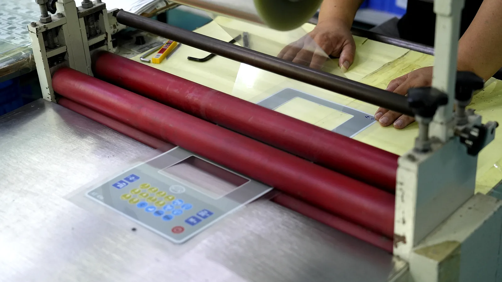
PET or PC overlay film
subsurface print / protective ink stack
pressure-sensitive transfer adhesive
finished enclosure surface: metal, molded plastic, paint, or powder coat
Enclosure structure
Record the selected graphic overlay materials—film, print stack, surface finish, and adhesive-side requirements—alongside the finished-enclosure specification.
The finished surface controls the first screen. 3M places PP and PE below its 36 dyn/cm LSE boundary, while many metals sit far higher. “Plastic housing” or “aluminum panel” therefore leaves the interface undefined when texture, treatment, paint or powder coat is present.
The adhesive that mounts custom graphic overlays is not automatically suitable between membrane-switch layers. Spacer, circuit and rear-mounting interfaces have other substrates and functions; use the separate membrane switch adhesive selection resource for those decisions.
A die-cut acrylic PSA transfer adhesive is a common thin starting construction; the 3M 467MP TDS names subsurface-printed PET/PC overlays. Deep texture, curvature, weak coating, a gap, exposed peel edge or service-removal requirement can make that construction wrong.
2. Graphic Overlay Bonding Fails as a Chain, Not a Single Event
Graphic overlay bonding usually becomes vulnerable before an edge visibly lifts. The chain begins when the adhesive cannot make enough molecular contact with the finished panel or when the assembly stores peel stress at a corner, cutout, curve, or local high spot.
| Stage | What happens at the bond line | Evidence to inspect |
|---|---|---|
| 1. Wrong surface assumption | The drawing names aluminum, but the adhesive touches a powder coat; or it names plastic without a resin grade and surface treatment. | Coating code, resin specification, supplier and lot; production-panel coupon. |
| 2. Incomplete wet-out | Low surface energy, texture, dust, oil, mold release, low application temperature, or inadequate pressure limits contact. | Contact pattern, trapped air, clean/dry record, roller or platen settings. |
| 3. Stored edge stress | Overlay stiffness, corner geometry, curvature, panel warp or a proud fastener loads the flexible film in peel. | Flatness map, cross-section, edge exposure, cutout and corner locations. |
| 4. Exposure amplifies the weak point | Heat/cold cycling, humidity, fluids or handling changes stress and adhesive response. | Conditioned coupons and full parts, not a room-temperature thumb test. |
| 5. A crack propagates | Separation starts at the stressed edge and travels into the bond area. | Peel path and failure mode: clean panel, adhesive split, coating transfer, ink/film damage. |
Keep three boundaries clear. Chemistry and texture are independent: 3M positions 468MP for slight HSE texture and 9472LE for textured LSE plastic or powder coat. (468MP; 9472LE) Visible lift may be coating failure; Avery Dennison flags retained solvent, weak paint and mold release. Finally, 3M’s joint guide shows why peel concentrates at a flexible edge. A stronger PSA cannot repair a weak coating or unprotected corner.
3. Graphic Overlay Adhesive Selection Decision Table
The first screen should combine the finished surface, its texture, and the mounting geometry. A resin or metal name by itself is not enough. The table below identifies a construction class to investigate; it does not release a tape for production.
| Finished surface presented to the adhesive | Texture and geometry | First construction to screen | What can overturn that screen |
|---|---|---|---|
| Bare stainless steel or clean aluminum | Smooth, flat, supported perimeter | Thin HSE acrylic transfer adhesive | Oil, oxide, conversion coating, unusual temperature/fluids, panel warp, or exposed peel edge |
| Anodized or chemically treated metal | Smooth and flat | HSE acrylic only after testing the exact finish | Seal chemistry, dye, process variation, cleaner compatibility, weak surface layer |
| Painted or powder-coated metal | Any finish | Treat the paint/powder as the substrate; screen LSE-capable chemistry when wet-out is poor | Coating cure, additives, gloss/texture, recoat, supplier/lot change, coating separation |
| PC or ABS housing | Smooth, flat | Thin acrylic documented for the finished plastic | Resin blend, recycled content, texture, hardcoat, antistatic additive, mold release |
| PP, PE or another verified LSE plastic | Smooth, flat | Thin LSE/high-tack acrylic candidate | Migrating additives, curvature, stress, fluid exposure, poor process control |
| Textured PP/PE or difficult textured plastic | Shallow, distributed texture | Thicker, conformable LSE construction | Peaks still prevent contact, deep grain, large gap, thin unsupported overlay, cleaner damage |
| Any substrate | Curved, warped, deeply recessed or locally gapped | Conformable carrier, foam tape, formed overlay, bezel or mechanical peel stop | Read-through, stack height, display-window alignment, service removal, ingress path |
| Any substrate | Overlay is a planned service item | Removable PSA or mechanical retention | Residue limit, cleaning process, replacement alignment, tamper requirement |
3M classifies PP and PE as LSE plastics, while Avery Dennison separates PC/ABS from PP/PE and powder coat. Treat both as screening maps; test the molded grade or coating actually supplied.
Choosing an overlay adhesive for textured plastic
An overlay adhesive for textured plastic needs matching chemistry and enough conformability. A thick HSE acrylic may fit textured PC yet fail on PP; a thin LSE formulation may match PP chemistry yet bridge only the peaks. Apply a production-equivalent overlay under controlled pressure, inspect voids, use the TDS dwell, then peel and record the failure path. tesa’s processing guide recommends softer adhesive, greater coat weight or a conformable carrier for some rough surfaces.
When a thin transfer adhesive is not the best choice
A die-cut transfer adhesive is not the best construction when the panel cannot maintain intimate contact across the bond line. Typical stop conditions are:
- compound curvature, panel warp or a gap that stores continuous peel;
- texture deeper than the candidate can wet under the controlled process;
- an uncured, weak or contaminated coating that cannot be corrected;
- clean-removal, repeat-replacement or mandated label-system requirements;
- a sharp reachable edge, dimensional mismatch or fastener-induced distortion.
Evaluate a conformable carrier or foam, formed overlay, mounting pocket, bezel, edge capture or another decorating method. Edge fasteners can act as peel terminators; full-part testing must still check fastener distortion.
4. The Eight-Point Evaluation Framework
The framework runs from the surface outward: finished-substrate identity, surface energy, topography, geometry, exposure, edge design, assembly process, and validation. A candidate that fails any one criterion should not reach the production drawing merely because its room-temperature peel value looks high.
4.1 Name the surface presented to the adhesive
Name the final process layer. “Aluminum” is incomplete when the panel is anodized, painted or powder-coated; “ABS” is incomplete after texture, coating or another secondary operation. Record the coating supplier/code, cure, gloss/texture and applicator, or the resin maker/grade, additive package, tool texture, recycled content, mold-release policy and surface treatment.
Drawing and coupon identify the finished surface and lot.
Base metal or generic plastic alone drives selection.
4.2 Separate surface energy from texture
Surface energy governs wet-out chemistry; texture governs real contact. 3M defines LSE as below 36 dyn/cm and includes PP and PE, but that boundary is a screen, not a finished-part specification. A textured LSE molding may need LSE chemistry plus greater adhesive mass or a conformable carrier; finger tack on the peaks proves neither wet-out nor holding performance.
A materials and adhesive selection review should therefore treat surface-energy class, texture, adhesive mass, carrier conformability, and overlay stiffness as one construction.
Energy class and texture are recorded, then contact is verified.
“Use 5 mil” appears without a chemistry check.
4.3 Verify coating cure, cohesion and cleanliness
The PSA cannot compensate for a weak layer below it. Low-energy powder-coat additives can reach the exposed surface; paint can also release from metal, and mold release can remain on plastic. Use only cleaners approved for the finish. ASTM D3359-23 can screen some coatings, but it is not an overlay-bond test.
Cure and cleaner compatibility are documented; failures are inspected.
Cleaner, primer or abrasion changes bypass finish review.
4.4 Map flatness, curvature and local gaps
A nominally flat enclosure may contain sink, bow, weld distortion, fastener pull-in or a recess step. Record flatness, curvature, recess depth, corner radii, gaps, unsupported spans and fasteners. 3M’s curved-surface guidance says thickness, conformability and compressibility affect contact. A flat coupon cannot reveal stored peel force in a curved overlay.
The trial represents worst curvature, gap and support.
Flat-steel peel substitutes for curved-part evidence.
4.5 Define exposure without turning a TDS maximum into service life
Define application temperature, normal operation, excursion duration, cycling, condensation, water path, cleaner concentration/contact, oil and UV—not one extreme number. The humidity, water, UV and thermal-cycle data on named laboratory specimens and labels them representative. ISO 9142:2003 guides ageing-condition selection but does not convert accelerated exposure into service life.
For industrial control interfaces, document the actual enclosure exposure in this format rather than inheriting a generic “indoor” or “outdoor” label.
Fluids, edge access, cycles and post-tests match use.
A TDS maximum becomes a finished-overlay life rating.
4.6 Protect the perimeter and define edge land
Edge land is the continuous bonded width between an edge or cutout and the nearest unbonded feature. One graphic-overlay checklist recommends 3 mm; treat 3 mm as a initial drawing screen, not a universal minimum or JASPER datum. Final width depends on peel load, corner radius, overlay stiffness, cutouts, recess protection, texture and flatness. Radius corners where possible, avoid adhesive slivers and dimension no-adhesive zones.
Carry the chosen edge land, corner radii, cutout clearances, and adhesive-free zones into the drawing with the graphic overlay design guide.
Minimum land, radii and adhesive-free zones are dimensioned.
“Full back” hides narrow, undocumented adhesive slivers.
4.7 Lock the assembly process
Specify the cleaner, dry check, surface temperature, liner sequence, alignment, pressure tool/range, speed, dwell and handling limit. The September 2025 3M 467MP TDS recommends 10–15 psi final-installation pressure, a 15.6–38 °C application range, and no application below 10 °C; those numbers apply to that guidance, not every PSA. Control roller load, hardness, width, speed and part support. Record dwell—the same TDS reports many peel values after 72 h.
A controlled tool and traveller capture temperature, pressure and dwell.
“Press firmly” is followed by immediate test or shipment.
4.8 Validate the construction and own the acceptance rule
Test the printed overlay, selected adhesive, production-equivalent panel and intended process across credible lots. ASTM D3330/D3330M-04(2025) covers transfer-tape peel on a surface of interest; peel results are not direct design information. ISO 8510-2:2006 or ASTM D903-98(2025) may fit a complete flexible-overlay/rigid-panel specimen. Record raw force and whether failure is panel release, adhesive split, coating transfer, ink separation or film tear. The OEM owns the acceptance limit.
The report preserves stack, lots, process, conditions, raw data and failure mode.
Stainless-steel TDS data “prove” a textured powder-coat bond.
5. Compare Documented Adhesive Candidates Without Ranking TDS Numbers
These examples separate chemistry for the surface class from adhesive mass for texture. Confirm current regional status and liner options at release.
| Documented candidate | Construction and nominal thickness | Surface/topography named by 3M | Stop condition before selection |
|---|---|---|---|
| 3M 467MP | 200MP acrylic transfer adhesive; 0.06 mm (2.3 mil) | Metal and HSE plastics; thin, smooth flexible material to a smooth surface | Do not default to it for PP, PE, unknown powder coat, visible texture or a persistent gap. |
| 3M 468MP | 200MP acrylic transfer adhesive; 0.13 mm (5.2 mil) | Metal and HSE plastics; extra caliper for slight texture or irregularity | Added thickness does not make 200MP an LSE chemistry or bridge an arbitrary gap. |
| 3M 9471 | Adhesive 300 transfer tape; 2.0 mil | Graphic overlays on metal and smooth LSE plastic | Thin construction still needs full contact; confirm environment and current product data. |
| 3M 9472LE | 300LSE acrylic transfer adhesive; 0.132 mm (5.2 mil) | PP, powder coating, textured LSE plastic and dissimilar plastic-to-metal bonds | Flush-stack, optics, ooze, die-cut detail or an HSE-only application may favor another construction. |
This is not a leaderboard. Avery Dennison, tesa and other makers offer alternatives; compare documented candidates on the same overlay, panel, process and conditioning.
One adhesive, six substrates, six peel results
The 467MP TDS illustrates why substrate-specific data matter. Its September 2025 table reports the following typical 90° peel values under one controlled setup: 23 °C, 72 h dwell, 2 mil aluminum-foil backing, ASTM D3330 and 300 mm/min peel speed.
| TDS substrate | 90° peel at the stated conditions |
|---|---|
| Stainless steel | 10.0 N/cm |
| ABS | 2.4 N/cm |
| Acrylic (PMMA) | 7.0 N/cm |
| Aluminum | 7.0 N/cm |
| Glass | 9.9 N/cm |
| Polycarbonate (PC) | 7.8 N/cm |
The spread shows substrate dependence, not an overlay minimum; 3M labels the data representative. Backing stiffness and adhesive rheology limit cross-tape comparisons under ASTM D3330/D3330M-04(2025). Use a common production-equivalent assembly test.
6. Use a Six-Step Specification and Approval Process
Finish with three controlled outputs: drawing callout, installation instruction and acceptance record.
Step 1 — Freeze the finished substrate callout
Collect production-equivalent panels before selecting the final adhesive. Record the information below in the RFQ or engineering review package.
| Input group | Required project information |
|---|---|
| Panel identity | Base material, resin/alloy grade, supplier, part revision and representative lots |
| Exposed finish | Paint/powder/anodize/hardcoat code, colour/gloss, texture, cure, secondary treatment and mold-release policy |
| Geometry | Bond outline, recess, cutouts, smallest edge land, corner radius, flatness tolerance, curvature, gaps and fastener locations |
| Environment | Application and service temperatures, cycling, humidity/condensation, water path, cleaners, oils, UV and storage |
| Assembly | Approved cleaner, application equipment, support fixture, pressure control, alignment method, dwell and packing sequence |
| Service / compliance | Planned removal, residue limit, safety-marking role, appearance criteria and change-control owner |
| Acceptance | Test specimen, method, conditioning, sample count, raw measurement, failure-mode rule and sign-off authority |
If the housing finish is not frozen, do not release the adhesive selection.
Step 2 — Mark the stress geometry on the drawing
Highlight corners, cutouts, narrow webs, recess steps, unsupported spans, curves and reachable edges. Dimension minimum land and mark the adhesive side to prevent a mirrored die cut. Measure overlay curl and panel warp; if the overlay must be forced into a recess, treat that restoring force as bond load.
Step 3 — Screen chemistry and construction from current maker data
Shortlist only from current documents that name the surface class. Record chemistry, carrier/transfer format, thickness, liner, die-cut behavior, application window, service limits, fluids, exclusions and document revision. The 467MP, 468MP, 9471 and 9472LE examples distinguish four screens; same-thickness substitutions still require review.
Step 4 — Build a small process-window experiment
Build production-stack coupons and vary only controlled inputs: approved cleaning state, TDS-supported pressure settings, application temperature and early/final dwell. Inspect contact and trapped air before destructive testing. Trace liner, adhesive lot, panel lot and machine setup.
Step 5 — Condition coupons and full parts
Run baseline peel or holding tests, apply the project’s heat, cold, humidity, condensation, fluid or water sequence, then retest after a declared recovery. Include full parts for geometry. ASTM D1183-03(2019) supports cyclic ageing comparisons but not a conversion to field years.
Step 6 — Release the drawing, process and first article together
Release the exact adhesive or controlled-equivalent rule, pattern, liner/back-split, edge land, no-adhesive zones, surface identity, preparation, temperature, pressure setup, dwell, inspection and validation record. First-article approval needs traceable surface/adhesive lots and results. Changes to resin, finish, cleaner, tape, converter, die cut or pressure equipment trigger impact review; purchasing cannot replace the control panel adhesive by thickness alone.
7. Build the Test Matrix Around the Real Failure Risk
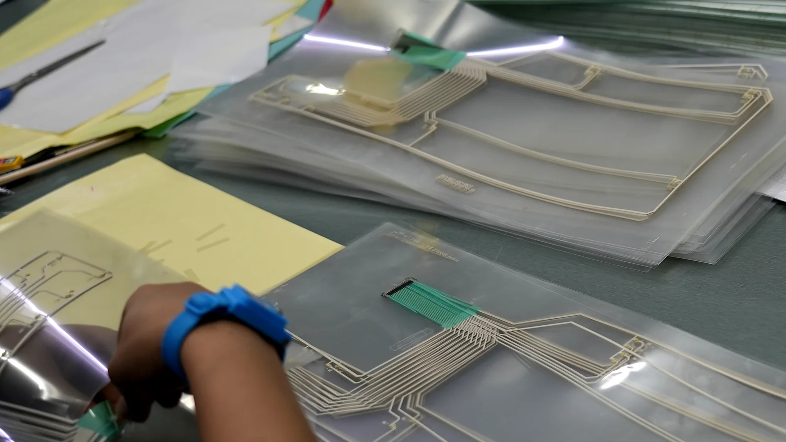
A useful adhesive and environmental testing matrix uses actual materials, repeats the production process, preserves failure modes and discloses any method modification.
ASTM D3654/D3654M-06(2024) measures constant-load parallel shear; standard steel may not represent another surface. ISO 29862:2024 includes 180° peel for transfer tapes. Claim conformance only after following the licensed procedure.
Sample approval checklist
Approve a sample only when the record answers each item:
- [ ] Film, print stack, adhesive, liner, die cut and drawing revisions match.
- [ ] Panels represent approved resin/coating, texture, cure and lots.
- [ ] Cleaner, application temperature, support, pressure setup and dwell are recorded.
- [ ] Pattern, back-split, cutouts, no-adhesive zones and smallest edge land match.
- [ ] Baseline/conditioned raw data and individual results are attached.
- [ ] Failure modes distinguish panel release, cohesive split, coating transfer, ink separation and film damage.
- [ ] Visual checks cover bubbles, edge lift, read-through, distortion, registration and service-removal residue where relevant.
- [ ] OEM acceptance limits, sign-off and revalidation triggers are explicit.
8. Release Blockers That Disqualify an Adhesive Proposal
These release blockers indicate that the proposal is not ready for drawing release, regardless of how familiar the tape number looks:
- “Bonds to metal and plastic” is the substrate description. Finish, resin grade, texture and contamination are missing.
- Thickness substitutes for chemistry. A 5 mil HSE acrylic is not automatically suitable for textured PP, and a thin LSE tape may bridge texture.
- TDS revision and conditions are absent. Peel without substrate, backing, angle, rate, temperature and dwell is unusable.
- Finger tack and “press firmly” define the process. Cleaner, temperature, pressure tool, support and handling time are uncontrolled.
- The adhesive pattern ignores geometry. Cutouts, corners, no-adhesive zones and minimum land are not dimensioned.
- Reference-panel data replace actual-part testing. ASTM D3330 limits what peel predicts; generic humidity cannot qualify an unknown coating.
- Surface or tape substitutions bypass review. Resin, coating, mold release, cleaner and tape construction can change the bond interface.
- A TDS or UL 969 becomes a life/compliance promise. UL Solutions ties recognition to defined systems and Conditions of Acceptability; neither source guarantees the finished overlay.
9. Frequently Asked Questions
What is the best adhesive for a graphic overlay on metal?
No single adhesive fits every metal panel. Screen 3M 467MP for clean, smooth HSE metal and 468MP for slight HSE texture, then test the finished surface. Paint, anodize, powder coat, oil, flatness, fluids and edge geometry can overturn that screen. (467MP; 468MP)
Which overlay adhesive works on textured plastic?
Match both surface energy and texture. 3M 468MP is a documented thicker screen for textured HSE plastic; 9472LE is a 5.2 mil 300LSE screen for textured LSE plastic or PP. Verify wet-out, edge lift and conditioned peel on the molded production finish.
Can 3M 467MP be used on powder-coated metal?
Do not select 467MP from the metal below the coating. Low-energy additives can reach a powder-coated surface. Test the coating lot; 9472LE may be a better screen when wet-out is difficult.
Is a thicker control panel adhesive always better?
No. Greater adhesive mass can improve contact on slight texture but also changes stack height, read-through, ooze, die-cut detail and window registration. Avery Dennison treats roughness and flatness together. Use the thinnest validated construction.
How much edge land should a graphic overlay have?
No universal width fits every overlay. An RH Technical Industries checklist gives 3 mm as preliminary guidance. Final land depends on corners, cutouts, curvature, texture, overlay stiffness, edge exposure and conditioned full-part results.
How much pressure is needed to install a graphic overlay?
Use the maker’s value and a controlled tool. The 467MP TDS recommends 10–15 psi for final installation; that is 200MP guidance, not a universal rule. Record tool setup, speed, part support and temperature.
How long should a bonded overlay dwell before testing?
Use a declared dwell tied to the candidate TDS. The September 2025 3M 467MP TDS reports many peel values after 72 h but does not set a universal PSA endpoint. Record early-handling and final-test dwell separately with temperature and load.
How should graphic overlay bonding be tested?
Graphic overlay adhesive selection should be verified on the overlay, adhesive, finished panel and production process. Use ASTM D3330 or ISO 29862 for suitable tape specimens, or ISO 8510-2 / ASTM D903 for a flexible-overlay/rigid-panel assembly. Add conditioning and full-part geometry; report raw force, dwell, rate, temperature and failure mode.
Does UL 969 make a graphic overlay adhesive compliant?
No. UL’s program evaluates defined marking constructions for specified surfaces and exposures. Conditions of Acceptability still apply, and the evaluation does not establish structural, electrical or flammability performance for the end product.
When should a thin PSA be replaced by foam or mechanical retention?
Change it when thin PSA cannot maintain contact or remains in continuous peel. Deep texture, gaps, compound curvature, warp, weak coating, reachable edges or repeated removal are triggers. Screen a conformable carrier, foam, formed overlay, pocket, bezel or peel stop and validate the full assembly.
10. Send the Substrate Finish and Mounting Geometry
An adhesive review can start before the artwork is final, but it cannot start from the overlay image alone. Send the finished substrate and mounting geometry: a production-equivalent panel or coupon; resin/alloy and finish identifiers; coating or texture specification; flatness and curvature; recess, cutout, corner and minimum-land dimensions; expected cleaners and fluids; application and service temperatures; moisture exposure; assembly pressure method; dwell and handling sequence; removal requirement; and the OEM acceptance owner.
Engineering teams can send the substrate finish and mounting geometry with this input set. JASPER can then discuss candidate graphic-overlay constructions and sample geometry. Other qualified overlay converters and adhesive specialists can apply the same evidence process. The useful next output is a short, testable candidate list and a coupon plan—not an unsupported promise that one tape will bond every enclosure.
Technical References
- Source: 3M 467MP TDS. Accessed 2026.
- Source: Avery Dennison. Accessed 2026.
- Source: Avery Dennison separates PC/ABS from PP/PE and powder coat. Accessed 2026.
- Source: tesa’s processing guide. Accessed 2026.
- Source: ASTM D3359-23. Accessed 2026.
- Source: ISO 9142:2003. Accessed 2026.
- Source: graphic-overlay checklist recommends 3 mm. Accessed 2026.
- Source: September 2025 3M 467MP TDS. Accessed 2026.
- Source: ASTM D3330/D3330M-04(2025). Accessed 2026.
- Source: ISO 8510-2:2006. Accessed 2026.
- Source: ASTM D903-98(2025). Accessed 2026.
- Source: 3M 467MP. Accessed 2026.
- Source: 3M 468MP. Accessed 2026.
- Source: 3M labels the data representative. Accessed 2026.
- Source: ASTM D1183-03(2019). Accessed 2026.
- Source: ASTM D3654/D3654M-06(2024). Accessed 2026.
- Source: ISO 29862:2024. Accessed 2026.
- Source: ASTM D3330. Accessed 2026.
- Source: UL Solutions. Accessed 2026.
- Source: 467MP. Accessed 2026.
- Source: 468MP. Accessed 2026.
- Source: RH Technical Industries checklist. Accessed 2026.
- Source: 467MP TDS. Accessed 2026.
- Source: UL’s program. Accessed 2026.
Review the finished overlay construction before release
Send the drawing, artwork, substrate, adhesive, assembly, environment, optical states, and acceptance evidence for a construction-specific review.