
TENS electrode pad design guide covering 9 geometry criteria, current distribution, hydrogel, lead attachment, edge effects, and validation.
Scope: This guide covers noninvasive, skin-contact stimulation-electrode component design and procurement preparation. It does not provide electrode-placement instructions, treatment settings, efficacy claims, patient-safety limits, or regulatory approval conclusions.
1. Pad Geometry Is an Electrical-System Decision
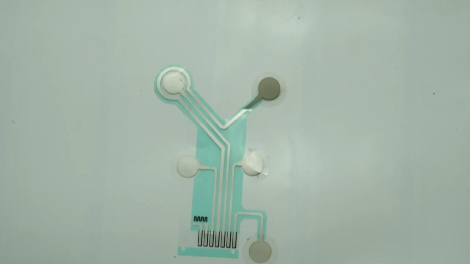
The outside die-cut shape is only the visible boundary. The electrically active boundary may be smaller because the pad can also contain a handling tab, foam border, adhesive margin, connector island, printed tail, strain-relief zone, or liner pull tab. A defensible drawing identifies the exposed active area separately from the backing outline.
Current also needs a complete loop. The generator output, lead or snap, printed bus, contact medium, skin and tissue path, return electrode, and return conductor belong to one electrical system. Changing the return-pad location or contact area can change the field even when the source pad is untouched. Thomas et al. Showed this in a 2021 finite-element TENS model: increasing conductive-contact separation from 13 to 43 mm affected modeled current flow more than a modest V-to-pill outline change. That result was anatomy- and device-specific, but the design lesson travels well—pair geometry matters (Thomas et al., 2021).
TENS, EMS, and NMES may share printing, converting, hydrogel, and connector operations. They do not share one universal electrical envelope or best pad. The equipment team must define pulse shape, maximum normal and fault current, compliance voltage, pulse width, frequency, duty cycle, phase sequence, channel behavior, and return path. Only then should the team review TENS, EMS, and NMES electrode-pad component options or the broader printed electrode-pad product family.
The manufacturing question is therefore not “Which shape is best?” It is “Which controlled stack produces the required field and mechanical fit under normal use, foreseeable contact loss, aging, and the intended waveform?”
2. Geometry and Current-Distribution Decision Table
No row in this table is a stand-alone selection rule. Each item changes at least one other item, so geometry should be reviewed as a coupled system.
| Design choice | Potential engineering benefit | Main tradeoff or failure mechanism | Not the best choice when | Evidence to request |
|---|---|---|---|---|
| Larger exposed area | Lowers nominal current-to-area ratio for the same total current; can cover a broad target | More difficult fit on curved anatomy; less spatial selectivity; greater edge-lift opportunity | A small target, tight placement window, garment seam, or adjacent structure controls selectivity | Active-area measurement, placement tolerance study, normal/fault waveform test |
| Circular or elliptical outline | Removes sharp external corners and may fit some anatomical contours | Perimeter edge concentration remains; feed-point asymmetry can still dominate | The target is long, segmented, or requires controlled directional coverage | Distribution model/map with actual feed and return geometry |
| Rounded rectangle | Uses package area efficiently while avoiding acute corners | Corner radius alone does not equal uniform current | The pad crosses a high-curvature or high-motion region | Radius and dielectric-window tolerances; partial-contact testing |
| Segmented array | Supports selectable channels or distributed placement | Gaps, routing, shared hydrogel, and inter-element shunting interact | The controller cannot constrain channel states or placement registration | Channel map, gap dimensions, interface-resistivity assumptions, fault matrix |
| Central conductor feed | Can shorten the longest current path in a symmetric pad | Creates a reinforcement island or local stack change; may conflict with placement | Cable exit, snap pressure, package height, or body contour makes the center impractical | Voltage-drop map, connector load test, current-distribution test |
| Edge feed or printed tail | Keeps connector hardware outside the main contact region | Long lateral paths can create voltage gradients; cable load can lift the edge | The bus cannot spread current before the active window | Worst-path resistance, strain-relief drawing, flex-under-load test |
| Uniform low-resistance conductor | Limits series drop across the current-spreading layer | A highly equipotential surface over resistive tissue can intensify perimeter crowding | The interface relies on controlled distributed resistance to smooth local current | Sheet/trace resistance method plus modeled or measured interface distribution |
| Higher-resistance interface layer | Can redistribute current in a qualified construction | Raises voltage demand; hydration, sweat, pressure, and aging can change resistance | The generator has limited compliance or the interface state is poorly controlled | Bulk/contact impedance under new, aged, hot/humid, and partial-contact states |
| Broad hydrogel coverage | Supports ionic contact across the active window | Dehydration, squeeze-out, contamination, liner effects, and edge mismatch can alter contact | Package barrier or dwell conditions cannot preserve the defined state | Exact material code, thickness, coverage, liner, conditioning, package-aging evidence |
A circle is not inherently “uniform,” and a broad pad is not inherently “comfortable.” Kim, Zieber, and Wang’s review describes why current tends to crowd near the perimeter when a low-impedance electrode contacts higher-resistivity tissue (Kim et al., 1990). The external outline can reduce one geometric stressor, such as an acute corner, while leaving the basic edge effect untouched.
3. Define the Stack and Current Path Before the Shape
A stimulation pad is a stack of electrical and mechanical boundaries. The layer order below is illustrative; a released BOM and drawing must define the actual materials and which surfaces contact skin.
GENERATOR / ACCESSORY
lead, snap, or tail
mechanical strain enters here
reinforcement + attachment interface
printed bus / current spreader
conductor under dielectric
active opening
conductive hydrogel / qualified interface
adhesive border, if separately used
SKIN
intended tissue current path
RETURN PAD + CONDUCTOR
Five boundaries should be visible on the controlled artwork:
- External outline — the converted part, including tabs and connector features.
- Active opening — the exposed area intended to transfer current through the contact medium.
- Current-spreading region — the conductor and bus that distribute output from the feed point.
- Insulated region — traces, overlaps, and keep-outs covered by dielectric or another barrier.
- Contact/adhesive region — hydrogel and any separate skin-adhesive area, including edge setback and liner split.
The current-spreading conductor can be carbon, a conductive polymer or rubber, a silver-based bus beneath another exposed layer, or a project-qualified combination. A material name is not a distribution model. Sheet resistance, cured thickness, conductor topology, dielectric overlap, attachment, and gel contact all affect the path.
The skin interface deserves the same precision. “Hydrogel” does not identify ionic composition, bulk resistivity, thickness, water content, tack, liner, storage condition, or behavior after repeated handling. The choice between a gelled and dry architecture is covered separately in the hydrogel versus dry electrode interface guide. For stimulation geometry, the important point is that the interface can redistribute current and change as it hydrates, dehydrates, warms, sweats, compresses, or lifts.
4. The Nine TENS Electrode Pad Design Criteria
4.1 Freeze the electrical envelope
Pad review begins with the maximum normal and fault waveform, not a nominal product category. Record current or voltage control mode, compliance voltage, pulse shape, pulse width, frequency, duty cycle, phase sequence, interphase interval, channel timing, load-detection behavior, and return path. If the generator uses presets, include the actual tolerances and fault states rather than only the user-interface labels.
A revision-controlled electrical input table connects each channel and electrode pair to normal, worst-case, and single-fault conditions.
The RFQ says only “TENS compatible,” “EMS pad,” power in watts, or connector type.
4.2 Separate external outline from exposed active area
The active area should be hatched and dimensioned. If the active window contains separate islands, state the area of each island and the total area that can be energized in every controller state. Keep handling tabs, connector islands, insulated traces, and inactive adhesive borders out of the calculation.
The drawing reports exposed area in cm² and ties it to a controlled dielectric opening and contact-medium boundary.
Nominal current density is calculated from the full foam or backing outline.
4.3 Review perimeter, corners, and dielectric overlap
A sharp corner can create a localized geometric peak, yet rounding corners does not eliminate perimeter concentration. In a 35 cm², 2 mA tDCS model, Minhas, Datta, and Bikson found edge concentration for both circular and rectangular electrodes; the rectangular model added localized corner peaks under its stated 0.5 mm conductor, 2.5 mm sponge, and conductivity conditions (Minhas et al., 2011). A related human comparison did not find a substantial shape-driven difference in perception thresholds, which is a useful warning against turning one simulated peak into a universal comfort claim (Ambrus et al., 2011).
Edge radius, active-window tolerance, dielectric overlap, conductor setback, and hydrogel coverage are reviewed together.
A circle is selected because it is assumed to have uniform local current density.
4.4 Design the current-spreading conductor
The feed point injects current into a finite-resistance layer. An edge-fed pad may need a bus or graded topology to limit voltage drop across the longest path. A central feed can shorten that path, but it may add a snap, rivet, reinforcement island, pressure point, or local change in gel thickness. Saturnino, Antunes, and Thielscher showed in a tDCS model that connector position and material conductivity could alter the modeled field; their result does not select a TENS architecture, but it confirms that feed location is not merely a packaging detail (Saturnino et al., 2015).
The released drawing identifies the conductor topology, feed, worst current path, sheet/trace resistance method, and voltage-drop assumption.
One end-to-end continuity reading is treated as evidence of uniform stimulation electrode current distribution.
4.5 Specify the hydrogel or other contact medium
Interface resistance can be a design variable. In the Minhas model, lowering sponge conductivity from 1.4 to 0.05 S/m made the calculated distribution more uniform. Sha et al. Separately tested one thin, high-impedance hydrogel electrode during functional electrical stimulation; under that crossover protocol it allowed 9% more current at equivalent sensation and reduced reported discomfort by 28% at higher levels (Sha et al., 2008). Neither study proves that a generic high-resistance hydrogel is best.
Higher distributed resistance may demand more generator voltage. The value can also shift with formulation, thickness, pressure, temperature, hydration, sweat, storage, reuse, and dwell. An exact material and aged-state test are required.
Material code, supplier revision, nominal thickness, converted area, liner, conditioning, package, and aged electrical method are controlled.
The BOM says only “medical hydrogel” or substitutes an “equivalent” roll without functional review.
4.6 Integrate lead, snap, or printed-tail attachment
Attachment determines where current enters and where mechanical load reaches the pad. A snap can compress local layers. A leadwire joint can add a rigid transition. A printed tail can shift the feed to an edge and create a repeated-flex zone. Reinforcement, dielectric coverage, conductor geometry, strain direction, attachment process, and cable exit should be designed together.
FDA K190700 provides one public example of a cutaneous-electrode family using conductive carbon film and hydrogel with either leadwire or snap constructions. Its broad dimensions and device-specific claims demonstrate variation; they are not JASPER specifications or universal industry limits (FDA K190700).
The drawing names the mating interface, attachment method, material stack, feed point, reinforcement, polarity/channel identification, and test-load direction.
The connection type is chosen after the active geometry and package have been frozen.
4.7 Model partial contact and anatomical fit
A flat, fully wetted bench coupon is a necessary simplification for some tests, not a complete use model. Curvature can wrinkle the center or lift an edge. Hair, sweat, skin preparation, cable tug, movement, and placement variation can change the effective contact. A pad that bridges a contour may have less active contact than its drawing area suggests.
Thomas et al.’s TENS model found that changing contact separation had a larger effect than modest external-shape changes in that forehead configuration. Kuhn et al.’s array simulation likewise showed that element gaps and interface resistivity interact (Kuhn et al., 2009). The finished-device risk analysis should therefore include placement spread, partial attachment, a lifted edge, a wrinkle, gel migration, and an open or degraded return path where relevant.
The sample plan includes controlled full-contact and foreseeable partial-contact configurations tied to actual anatomy and application sequence.
Every functional test uses a rigid flat plate and reports only the fully covered result.
4.8 Validate at the correct evidence level
Printing and converting records answer component questions: geometry, registration, continuity, trace resistance, dielectric coverage, attachment, liner, and cosmetic acceptance. They do not answer finished-device questions such as local field, treatment performance, biological safety, normal and fault output, or regulatory suitability.
IEC 60601-2-10 Edition 2.2 covers nerve and muscle stimulators, including TENS and EMS, at medical electrical equipment level (IEC 60601-2-10). Its 2 mA/cm² provision is a scoped risk-analysis and operator-attention trigger under the standard’s current conventions—not an unconditional maximum and not proof that a design below it is safe or compliant. ISO 14971:2019 frames device risk management, while ISO 10993-1:2025 frames biological evaluation within that risk process (ISO 14971; ISO 10993-1).
Every test identifies specimen, fixture, waveform, environment, conditioning, acceptance limit, sample plan, record, and owner.
A supplier continuity test or one impedance value is presented as finished-equipment validation.
4.9 Control changes and aged states
An unchanged die line does not mean an unchanged electrode. New ink, hydrogel, substrate, liner, adhesive, attachment hardware, cure profile, roll width, die, package, or supplier can change geometry or current transfer. Revision control should link artwork, BOM, process, inspection, fixture, software waveform, and approved sample.
The change matrix defines which substitutions trigger material review, first article, electrical remapping, mechanical retest, aging work, or equipment validation.
“Equivalent material” is accepted from cost or availability data without construction-specific evidence.
5. EMS Electrode Pad Geometry and NMES Tradeoffs
EMS and NMES electrode pads often need to recruit motor structures, so area and placement interact with muscle dimensions, nerve depth, subcutaneous tissue, required selectivity, and the mechanical placement method. A small electrode can offer a more selective field, but it also raises nominal current density at the same total current. A broad electrode spreads the arithmetic average and may cover a larger target, yet it can recruit adjacent structures or fit poorly on a curved body site.
Flodin et al. Compared 2 × 2 cm, 5 × 5 cm, and 5 × 9 cm electrodes in 15 healthy participants during low-intensity NMES. The two larger sizes were more comfortable and required lower nominal current density for visible contraction in that protocol; placement also affected the result (Flodin et al., 2022). The finding supports testing multiple sizes and positions. It does not make 5 × 9 cm a universal recommendation.
Kuhn et al. Found that the preferred forearm stimulation-electrode size depended on nerve depth and adipose thickness: smaller electrodes could suit shallow targets, while larger electrodes could suit deeper targets in the tested models and measurements (Kuhn et al., 2010). This is why larger is not always better. The design target may be broad activation, selective activation, stable placement, low-profile wear, garment registration, or another system objective. The device team must state which objective wins when they conflict.
For an array, define every channel state. Which elements can energize together? Is the return shared? Does one hydrogel bridge adjacent elements? What happens if a gap closes under compression or if one island lifts? EMS electrode pad geometry cannot be released from artwork alone; it needs the controller truth table and the intended body map.
6. Nominal and Local Stimulation Electrode Current Distribution
Nominal geometric current density is easy to calculate:
Jnom = current / active area
Jnom = nominal geometric current density
current = total electrode current under the stated convention
area = exposed active area, not the external backing outline
50 mA ÷ 50 cm² = 1 mA/cm² nominal
This example is not a treatment setting, JASPER specification, safe limit, local peak, or IEC compliance statement. It does only one job: catch gross mismatches among stated current, stated active area, and the drawing.
Local current density is harder. It can rise near the perimeter, sharp dielectric openings, a feed point, a conductor transition, a thin interface region, a wrinkle, or the boundary of remaining contact after lift. It can also redistribute through a resistive hydrogel or conductive layer. Kim et al. Reviewed the edge effect across analytical, numerical, and experimental approaches. Kronberg and Bikson later modeled how sponge thickness, saline concentration, conductor size and placement, excess fluid, and rivets could shift a tDCS assembly between edge- and center-concentrated patterns (Kronberg & Bikson, 2012).
The practical hierarchy is:
- Arithmetic screen: calculate current divided by controlled active area.
- Circuit screen: calculate conductor and connector voltage drop under stated current and temperature.
- Field model: include active/return geometry, conductor, contact medium, anatomy, and boundary conditions appropriate to the decision.
- Bench map: use a justified fixture to compare new, conditioned, aged, and partial-contact pads.
- Finished-system validation: test the intended equipment, accessory, placement range, waveform, and fault controls.
Do not claim that a colored FEM plot proves patient safety. Mesh, tissue properties, contact impedance, anatomy, placement, and solver assumptions need sensitivity analysis. A model is most useful when it ranks design variants and exposes which assumptions control the result.
7. Follow the Failure Chain, Then Assign the Test
Current-distribution complaints often begin as material or mechanical changes. The chain below prevents a team from testing only the symptom.
Cable tug / curved anatomy / liner error / gel aging
wrinkle, lift, or thin contact zone
effective active area changes locally
interface impedance and current path redistribute
voltage demand, edge peak, output monitoring, or sensation changes
equipment response + use outcome must be investigated
Failure and evidence matrix
| Observed condition | Plausible upstream cause | Distribution consequence | Component evidence | Finished-system evidence |
|---|---|---|---|---|
| Hotspot in a bench map | Sharp active-window transition, local thin gel, feed asymmetry, fixture artifact | Local peak above arithmetic average | Window dimensions, gel thickness map, conductor resistance, repeat fixture | Model/measurement correlation under intended waveform and placement |
| Rising voltage demand | Gel dehydration, reduced contact, higher interface resistance, poor return | Generator approaches compliance limit; field changes | Aged interface impedance and package records | Output waveform and monitoring across normal/fault loads |
| Edge lift during use simulation | Curvature, adhesive mismatch, cable strain, liner/application sequence | Active area shrinks; perimeter moves inward | Peel comparison, strain path, converted dimensions | Simulated-use adhesion plus electrical mapping under partial contact |
| Uneven array activation | Gap tolerance, shared gel shunt, channel mismatch, placement shift | Some elements dominate or lose selectivity | Gap/registration inspection, channel resistance | Controller truth-table and anatomical placement validation |
| Feed-point discoloration or damage | High joint resistance, narrow bus, attachment defect, local flex | Voltage drop or heating near connection | Four-wire joint/bus resistance, attachment section, flex test | Worst-waveform thermal/electrical evaluation |
| Changed result after storage | Gel water loss/gain, liner transfer, adhesive flow, conductor corrosion, package leak | Interface and contact distribution drift | Real-time/accelerated aging with defined package | Critical waveform, distribution, adhesion, and use tests after aging |
| Intermittent output | Lead fatigue, snap movement, cracked trace, tail crease | Transient open/partial path | Continuity during flex and retention loading | Equipment fault detection and recovery behavior |
| Dielectric exposure mismatch | Print registration or die-cut variation | Active area and edge geometry depart from model | Optical/dimensional inspection against datums | Worst-tolerance functional confirmation |
| Evidence level | Typical test method | New sample | Conditioned / aged sample | Partial-contact or fault sample | Release record |
|---|---|---|---|---|---|
| Printed conductor | Artwork/dimensional inspection; continuity; four-wire resistance where specified | Required | As risk analysis directs | Flex/open-path case where relevant | Drawing revision, fixture, limit, sample count |
| Active window | Optical measurement of opening, overlap, radius, and registration | Required | Recheck after selected aging | Worst-tolerance sample | Measurement report and capability record where agreed |
| Contact medium | Thickness, coverage, controlled impedance/resistivity method | Required | Required for claimed storage/use states | Wrinkle, lift, reduced coverage, or contamination cases from risk analysis | Material lot, conditioning, method, result |
| Attachment | Joint resistance, retention, flex, and strain in defined direction | Required | Recheck after package/aging where relevant | Cable tug, rotated snap, tail crease, or intermittent case | Load profile, cycles, failure definition |
| Pad assembly | Distribution comparison on justified fixture under stated waveform | Required | Required for critical aged states | Defined partial-contact configurations | Fixture drawing, waveform, environmental conditions, map/statistic |
| Generator + accessory | Delivered waveform, compliance behavior, monitoring, and recovery | Required | Required with aged pad/load range | Open, degraded return, lifted pad, wrong connection as applicable | Hardware/software revision and fault response |
| Finished equipment | Risk controls, use simulation, biological evaluation, basic safety, essential performance | Required by device plan | Required by shelf-life/use claims | Foreseeable misuse and single-fault cases | Legal-manufacturer validation and regulatory file |
Validation ownership matrix
| Evidence layer | Typical questions | Primary owner | Boundary |
|---|---|---|---|
| Incoming material | Is the exact conductor, dielectric, substrate, hydrogel, adhesive, liner, and attachment material controlled? | Component manufacturer with approved suppliers | Identity and incoming properties do not prove pad performance |
| Printed circuit | Are active window, bus, registration, continuity, resistance, and dielectric coverage within released limits? | Component manufacturer | Does not prove skin current distribution |
| Converted pad | Are die cut, lamination, gel coverage, liner, attachment, reinforcement, and package configuration correct? | Component manufacturer / converter | Does not prove intended anatomical fit or treatment performance |
| Conditioned / aged pad | Do critical dimensions, interface behavior, adhesion, and attachment remain within project limits? | Shared; method and owner defined by contract | Accelerated aging needs a justified relationship to real time |
| Accessory + generator | Is the waveform delivered across expected loads, contacts, cable states, and faults? | Equipment/accessory developer | Requires actual or justified equivalent electronics and software |
| Finished medical equipment | Are basic safety, essential performance, usability, biological evaluation, risk controls, labeling, and regulatory evidence adequate? | Legal manufacturer with qualified laboratories and regulators | Cannot be granted by a printed-component supplier |
The manufacturer’s quality and testing framework can organize component controls, but the quoted test list must be confirmed for the actual construction. “Tested” is not a complete requirement. Name the specimen, fixture, current convention, waveform, environment, conditioning, limit, sample count, and disposition rule.
8. Six Steps From Waveform to Approved Pad
Step 1 — Issue the electrical and use inputs
Provide channel count, source/return relationship, maximum normal and fault waveform, compliance voltage, pulse timing, duty cycle, operating sequence, connector, body location, placement envelope, application/removal sequence, reuse policy, package, and target markets. If recording is also required, define the operating states and artifact-recovery requirement; the recording versus stimulation electrode guide explains why a dual-function pad is a separate architecture.
Step 2 — Draw three boundaries and one load path
Draw the external outline, exposed active area, and hydrogel/adhesive area separately. Then draw the mechanical path from cable or connector into reinforcement, substrate, adhesive, and skin. Mark datums, keep-outs, bending zones, dielectric overlaps, edge radii, gel setback, feed location, return, and liner split. The custom printed medical electrode design guide covers the broader drawing package.
Step 3 — Screen the architecture
Calculate nominal current-to-area ratio using the active opening. Calculate worst conductor and attachment drop. Compare central versus edge feed, candidate outlines, active/return separation, gel/interface assumptions, and partial-contact cases. Use finite-element modeling only at the fidelity needed for the decision, and record material properties and boundary conditions.
Step 4 — Build controlled variants
Prototype deliberate variables rather than a collection of unlabeled shapes. Examples include two feed positions, two active-window radii, two gel thicknesses, or two area options. Hold the remaining stack constant. Assign a unique drawing and BOM revision to every variant so electrical and mechanical results remain traceable.
Step 5 — Close component and system evidence
Approve dimensions, print, dielectric, conversion, gel coverage, attachment, liner, and package at component level. Then test new, conditioned, aged, and foreseeable partial-contact pads with the intended generator/accessory or a justified equivalent fixture. Include placement tolerance and return-path cases from ISO 14971 risk analysis. Biological evaluation under ISO 10993-1 remains a finished-device program, not a raw-material checkbox.
Step 6 — Release and control changes
Freeze artwork, BOM, suppliers, process parameters, inspection, golden sample, fixtures, generator/software revision, packaging, and approval records. Define which material, dimensional, process, or supplier changes trigger first article, current remapping, mechanical retest, aging work, or regulatory assessment. A cheap substitution made after validation can be the most expensive geometry change in the program.
Sample-approval closeout
| Approval item | Supplier record | Device-team record | Release question |
|---|---|---|---|
| Identity | Drawing, BOM, material lots, process route | Approved design inputs and intended accessory | Did both teams test the same revision? |
| Geometry | Outline, active window, gel coverage, feed and return features | Placement envelope and tolerance analysis | Does manufactured geometry match the modeled/tested geometry? |
| Electrical | Conductor/joint checks under agreed methods | Waveform, distribution, compliance, normal/fault behavior | Are component limits linked to system acceptance? |
| Mechanics | Attachment, flex, liner, package, converted dimensions | Application, movement, partial contact, removal/use sequence | Do test loads represent the real load path? |
| Aging | Conditioned component and package records | Critical performance after justified aging | Does the release state include the claimed storage/use state? |
| Change control | Supplier-change notice and first-article triggers | Revalidation and regulatory-assessment rules | Can either side change a critical input without review? |
9. Drawing and RFQ Checklist
A usable sourcing package should let an engineer reconstruct the electrical path without guessing from a rendering.
Drawing and input checklist
- [ ] Declare modality and operating state: TENS, EMS, NMES, combined, sequential, or another defined mode.
- [ ] Provide maximum normal and fault waveforms, compliance voltage, pulse width, frequency, duty cycle, phase sequence, and return path.
- [ ] Dimension external outline and each exposed active area separately; state area in cm².
- [ ] Mark conductor/bus topology, feed location, sheet/trace requirements, dielectric openings, overlaps, and keep-outs.
- [ ] Specify substrate, conductor, dielectric, hydrogel/contact medium, adhesive, backing, liner, reinforcement, and package by controlled grade.
- [ ] Define snap, lead, or printed-tail attachment, mating interface, polarity/channel identification, strain direction, and retention requirement.
- [ ] State body-location envelope, curvature, movement, placement tolerance, and application/removal sequence without adding treatment instructions.
- [ ] Define new, conditioned, aged, reused-if-applicable, and partial-contact test states.
- [ ] Name each test’s specimen, fixture, waveform/frequency, environment, limit, sample plan, record, and owner.
- [ ] Identify applicable market, device classification, standards edition, regulatory owner, and change-control triggers.
Nine disqualifying release blockers
- The active area is not dimensioned. The team cannot perform even a nominal current-density screen.
- The return path is absent. Source geometry alone cannot define the field.
- The waveform is described only by a retail mode name. Pulse and fault conditions remain unknown.
- “Medical hydrogel” is the complete material specification. Electrical and aging behavior cannot be controlled.
- The connector is not in the current-path review. Feed location and mechanical strain become hidden variables.
- A circle is claimed to eliminate edge effects. The design premise conflicts with published interface models.
- Only full-contact flat-fixture tests are planned. Curvature, lift, placement, and cable load remain unexamined.
- A component resistance result is called device validation. Evidence ownership is blurred.
- Equivalent-material substitution needs no requalification. The released current-distribution assumptions can change without notice.
10. Frequently Asked Questions
What is the most important dimension in TENS electrode pad design?
The most important controlled dimension is usually the exposed active area, but it cannot be reviewed alone. The device team must pair it with the normal and fault waveform, active/return separation, conductor feed, interface material, and intended contact conditions. The outside backing dimensions are not a substitute.
Does a larger TENS pad always distribute current more evenly?
No. A larger area lowers nominal current per cm² at the same total current, but local distribution still depends on perimeter, conductor topology, hydrogel, connector location, anatomy, placement, and partial contact. A larger pad may also reduce selectivity or fit poorly on curved anatomy.
Are round electrodes better than rectangular electrodes?
Neither shape is universally better. A round outline removes sharp corners, while a rounded rectangle may use package area more efficiently. Both retain perimeter edge effects. In area-matched research, modeled corner peaks did not translate into a universal difference in perceived stimulation, so the complete construction needs testing.
How should EMS electrode pad geometry differ from TENS geometry?
EMS electrode pad geometry should be selected around the target muscle or nerve, desired selectivity, tissue depth, placement tolerance, and controller waveform. TENS and EMS can use similar materials, but one outline is not automatically interchangeable. Larger and smaller electrodes each have documented tradeoffs under specific protocols.
What must be specified for NMES electrode pads?
Specify active and return areas, body-location envelope, channel map, waveform and faults, conductor routing, hydrogel/contact medium, attachment, placement sequence, and functional acceptance tests. For NMES electrode pads, placement and area should be validated together because both can alter activation and comfort in study-specific results.
Is total current divided by pad area a sufficient current-density test?
No. The current-to-area ratio is a nominal arithmetic screen. It cannot locate edge, corner, feed-point, wrinkle, or partial-contact peaks. Use it to check the drawing, then add a justified field model or mapping method and finished-system tests under the intended waveform and contact states.
Can hydrogel be used to improve stimulation electrode current distribution?
A controlled resistive interface can redistribute current in some constructions, and published modeling and human studies support that mechanism under specific conditions. Hydrogel chemistry, thickness, hydration, pressure, aging, and generator compliance all matter. A generic high-resistance hydrogel is not automatically the best choice.
Which tests belong to the electrode supplier and which belong to the device owner?
The supplier may control agreed material identity, geometry, registration, continuity, resistance, dielectric coverage, lamination, attachment, liner, and packaging checks. The device owner controls finished-system waveform delivery, local distribution acceptance, use simulation, biological evaluation, risk management, clinical claims, labeling, and regulatory authorization.
11. What to Send for Engineering Review
Technical References
- Source: FDA Use of ISO 10993-1 Biological Evaluation Guidance. Accessed 2026.
- Source: ISO 10993-1:2025 Biological Evaluation of Medical Devices. Accessed 2026.
- Source: ISO 14971:2019 Medical Device Risk Management. Accessed 2026.
- Source: FDA Design Control Guidance for Medical Device Manufacturers. Accessed 2026.
- Source: Thomas et al., 2021. Accessed 2026.
- Source: Kim et al., 1990. Accessed 2026.
- Source: Minhas et al., 2011. Accessed 2026.
- Source: Ambrus et al., 2011. Accessed 2026.
- Source: Saturnino et al., 2015. Accessed 2026.
- Source: Sha et al., 2008. Accessed 2026.
- Source: FDA K190700. Accessed 2026.
- Source: Kuhn et al., 2009. Accessed 2026.
- Source: IEC 60601-2-10. Accessed 2026.
- Source: ISO 14971. Accessed 2026.
- Source: ISO 10993-1. Accessed 2026.
- Source: Flodin et al., 2022. Accessed 2026.
- Source: Kuhn et al., 2010. Accessed 2026.
- Source: Kronberg & Bikson, 2012. Accessed 2026.
Review waveform, active area, and pad geometry
Send the current drawing, material stack, electrode roles, connector, use conditions, acceptance methods, program phase, and annual volume.