
A keypad is usually the better architecture when several controls share one operating workflow, front graphic, controller, feedback policy, and host interface. Individual switches are usually cleaner when the functions are few, physically distributed, independently serviced, or expected to present simple discrete outputs. This capacitive touch keypad vs switch decision is therefore about system grouping—not two different sensing principles. OEM electrical, mechanical, firmware, and sourcing teams should decide it only after defining key count, spacing, simultaneous touches, feedback, environment, and final-equipment validation.

1. Quick Verdict: Group the Workflow, Not Just the Electrodes
A capacitive keypad contains multiple touch sensors. An individual capacitive switch is one binary sensor used as a separate control. Either architecture may use self-capacitance or mutual capacitance, and several “individual” switches may still share one controller. The meaningful difference is how the inputs are packaged, mapped, serviced, and validated.
| Project condition | Better starting architecture | Why |
|---|---|---|
| Six or more controls on one operator surface | Capacitive touch keypad | One graphic, channel map, feedback policy, connector, and host message set can be engineered together. |
| One to three controls in different equipment locations | Individual capacitive switches | Local outputs, cables, housings, and service boundaries remain independent. |
| Numeric entry, menu navigation, lockouts, or key combinations | Keypad | The controller and host can coordinate sequence, adjacency, debounce, timeout, and accepted-state feedback. |
| A power, wake, dispense, or door command needs a simple local input | Individual switch | A dedicated or few-channel controller can expose a straightforward output without a full keypad protocol. |
| Sliders, wheels, proximity wake, or gesture zones share the same surface | Keypad | Mixed widgets can share graphics, sensing resources, timing, and feedback—if the selected controller supports them. |
| Controls cross safety, access, or replaceable-module boundaries | Individual switches or a hybrid | Independent wiring and fault containment may matter more than channel consolidation. |
| Eyes-free, emergency, or heavy-impact actuation is required | Often neither flat capacitive option | A guarded mechanical, tactile membrane, piezo, or hybrid control may give a more appropriate physical confirmation and risk boundary. |
A grouped keypad is not automatically cheaper, faster, or more reliable. It concentrates controller selection, firmware, artwork, stack-up, and validation into one assembly. That concentration is valuable only when the controls belong together.
2. What Counts as a Capacitive Keypad or an Individual Switch?
Microchip defines a capacitive button as a zero-dimensional sensor interpreted as a binary touched/not-touched state. A keypad arranges several of those binary controls into one coordinated interface; it may also add sliders, wheels, or proximity zones. The market terms “button,” “key,” “touchkey,” and “switch” overlap, so the drawing must define behavior rather than rely on a label.
A typical capacitive touch keypad has this installed signal path:
Finger / specified glove
Printed cover lens or graphic overlay + adhesive
Button electrodes / Tx-Rx intersections / guard or shield
Touch controller + channel configuration + scan schedule
Key map / lockout / gesture or slider processing
serial bus, synchronous serial bus, asynchronous serial bus, or another host interface
Host accepts or rejects the command
LED, display, sound, or haptic acknowledgement
The common cover and graphics are only the visible part. A production keypad also needs a connector, ground strategy, LED routing, host protocol, firmware ownership, boot behavior, fault handling, and a test fixture capable of addressing every key.
An individual capacitive touch switch can use a shorter path:
Finger / specified glove
Local nonconductive cover + electrode
Single- or few-channel controller
Logic, open-drain, PWM, or local serial output
Machine input / local host function
Microchip’s MTCH10XX documentation illustrates this class with one-, three-, and six-sensor devices. Infineon’s MBR3 family shows another option: a configurable controller can handle as many as 16 buttons. These examples prove that “individual” does not require one IC per key. A group of separate functions can share silicon while retaining separate output semantics, connectors, locations, or service rules.
The physical stack can also be part of a broader capacitive touch panel or an integrated HMI assembly. That manufacturing boundary should not silently decide the electrical architecture. First define what the operator does and what the host must know; then group the electrodes.
3. Capacitive Touch Keypad vs Switch: Engineering Matrix
The matrix below compares architectures under the same eight dimensions. It does not declare a universal winner because controller family, overlay, ground, cable, enclosure, display, firmware, and operating conditions can reverse the result.
| Dimension | Capacitive touch keypad | Individual capacitive switches | Decision boundary |
|---|---|---|---|
| Functional grouping | One coordinated set of keys and optional widgets | Separate local commands or modules | Group controls that share one task model; separate controls that must fail, change, or be serviced independently. |
| Channel/controller plan | Dedicated channels, shared lines, or a Tx/Rx matrix; resource plan covers guards, proximity, sliders, and spares | One or a few channels per local node; several nodes may share a controller | Count controller resources, compatible pins, scan blocks, feedback outputs, and host interface—not printed keys alone. |
| Sensing topology | Self-capacitance can be simple; mutual capacitance can support dense matrices and independent intersections | Self-capacitance often suits isolated high-sensitivity buttons; mutual sensing is still possible | Select topology from sensitivity, spacing, simultaneous-touch, moisture/noise, and scan requirements. |
| Touch keypad layout | Common pitch, graphic hierarchy, adjacent-key rejection, bezel, and finger/glove envelope | Each control can use a different cover, location, electrode, and guard condition | A common layout helps consistency; local switches fit distributed equipment geometry. |
| Multiple inputs/widgets | Better home for key sequences, chords, sliders, wheels, proximity, and gestures | Binary local behavior is easier to isolate | State every required simultaneous input and widget before controller selection. |
| Host integration | A serial interface can deliver key IDs, status, diagnostics, and events | Discrete outputs can connect to PLC or MCU inputs with limited protocol work | A serial keypad reduces host pins but adds protocol, boot, timeout, and fault-state obligations. |
| Feedback/graphics | LEDs, display prompts, legends, and feedback logic can be coordinated | Each switch can have a local indicator or depend on machine feedback | Confirm the accepted host action, not just the raw touch threshold crossing. |
| Validation/change control | One common stack, but many interactions and a larger regression set | Smaller local test scope, but several covers/cables/environments may differ | Validate the installed assembly and define which material, artwork, housing, ground, or firmware changes trigger retest. |
Texas Instruments, Microchip, and Infineon all tie touch performance to electrode geometry, overlay, routing, grounding, and controller configuration. Those variables remain present in both columns. A keypad can reduce connector or host-pin count, yet increase scan scheduling and software scope. An individual switch can simplify one function, yet multiply local controller, cable, or enclosure variants across the machine.
The electrical matrix is not the user-interface definition
A 16-button self-capacitance matrix can use eight GPIOs in the documented controller architecture. That pin-count advantage does not define the user interface. Self-capacitance matrices are suited primarily to one-button-at-a-time operation because diagonal simultaneous touches can be ambiguous. Use a mutual-capacitance matrix when the released chord set requires simultaneous detection, then validate the added scan workload on the selected controller.
A keypad with eight dedicated self-capacitance channels is still a keypad. Eight independent machine commands read by one eight-channel controller may still be individual switches from the system-design perspective. Draw both the operator grouping and electrical topology; do not let one diagram substitute for the other.
4. Where a Capacitive Touch Keypad Wins
A keypad wins when coordination creates more value than independence. Three gains usually justify the grouped architecture: dense input, shared behavior, and one controlled visual surface.
4.1 Dense, related controls can share resources
Numeric entry, recipe selection, menu navigation, and equipment setup place several actions in one operator zone. A keypad can use dedicated channels or shared Tx/Rx lines, then deliver key IDs over a serial interface. The host may need fewer input pins, but the touch controller now owns scanning, thresholds, key-state timing, and possibly error reporting. The gain is architectural only when those responsibilities are explicit.
A matrix can make a high key count practical. Infineon’s documented eight-GPIO/16-button example shows the principle. It also exposes the question that a simple pin-count spreadsheet misses: must the interface recognize two keys at once? If yes, the chosen mutual-capacitance controller, scan period, firmware, and acceptance logic must demonstrate that behavior.
4.2 Graphics and feedback can behave as one HMI
Grouped capacitive touch buttons can share one graphic language, backlighting system, dead-front treatment, display window, and feedback policy. The UI can illuminate only valid choices, disable unavailable functions, or guide a sequence. These are system behaviors, not properties of the printed overlay.
The acknowledgement loop matters. A local LED driven directly by a touch-controller output can indicate that the sensor crossed a threshold. It does not necessarily prove that the host accepted a dispense, motion, or access command. For consequential operations, route feedback from the accepted machine state or make the distinction visible.
4.3 Sliders, wheels, proximity, and gestures fit a common surface
Controller platforms from TI, Microchip, and Infineon support combinations of buttons, sliders, wheels, touchpads, and proximity sensors. A keypad architecture gives those widgets a common coordinate system and scan schedule. It can also coordinate wake-up behavior and display prompts.
That flexibility is not free. A slider consumes electrodes or intersections; proximity may need a large sensor, guard, or different scan settings; gestures need defined temporal logic. Adding one widget late can alter channel allocation, scan time, ground pattern, artwork, and regression testing. Reserve it in the first channel plan.
4.4 When a keypad is not the best choice
Do not group controls merely because they are all capacitive. A full keypad is a poor fit when controls live on different doors or replaceable modules, require separate hardwired outputs, use different cover stacks, or cross fault-containment boundaries. It is also questionable when one control must remain available while the shared controller, serial bus, or panel is restarting. In those cases, independent switches or a hybrid preserve a clearer system boundary.
5. Where Individual Capacitive Switches Win
An individual capacitive switch wins when local simplicity, distribution, or independence matters more than a unified panel. The architecture is especially useful for one-purpose commands placed near the function they control.
5.1 Distributed controls avoid a forced central panel
A machine may need a wake key near a handle, a light control inside a compartment, and a service input behind a door. Turning those locations into one keypad can add long sensor traces or tails, difficult routing, extra connectors, and confusing user grouping. Local electrodes with short routes and local controllers can keep each sensing environment understandable.
The covers may differ too. A switch behind 2 mm plastic beside a grounded metal bezel does not behave like one behind 4 mm glass on a polymer door. Separate nodes allow each electrode, threshold, and guard design to match its real stack rather than compromise around one common configuration.
5.2 Discrete outputs can fit existing machine inputs and outputs
A PLC or legacy MCU may expect a dry-contact-like logic state rather than a serial key code. A single-/few-channel controller can expose a digital or open-drain output and keep the host integration narrow. Microchip’s MTCH1010/1030/1060 family illustrates one-, three-, and six-sensor implementations; it does not remove the need to define active state, timeout, startup, stuck-touch behavior, and fault response.
The benefit disappears if the equipment ends up with many local controller boards, power rails, cables, and repeated firmware/configuration variants. At that point, a central keypad or distributed serial node may be easier to manufacture and diagnose.
5.3 Service and revision boundaries stay local
When one switch belongs to a replaceable subassembly, independent construction can keep a cosmetic or mechanical change from forcing a complete panel requalification. A field technician may replace one door module rather than the entire HMI. The OEM can also maintain a critical switch under a different drawing and approval process from convenience controls.
Independence needs discipline. Reusing the same part number across different bezels, cable lengths, grounds, or overlays can create hidden variants with different signal margins. Each installed condition still requires a controlled stack, configuration, and acceptance test.
5.4 When individual switches are not the best choice
Avoid a collection of isolated switches when the operator sees one keypad, the host needs key IDs and sequence logic, or every key requires coordinated lighting and diagnostics. Separate local outputs can consume connector pins and harness conductors, make artwork alignment harder, and scatter feedback behavior. If the controls form one task in the operator’s mind, the engineering documentation should usually treat them as one HMI too.
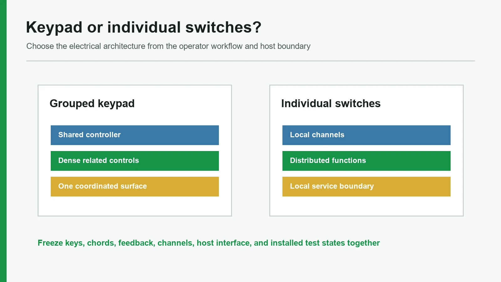
6. Build the Touch Keypad Layout and Channel Plan Together
A touch keypad layout is not finished when circles and legends fit on the drawing. Electrode size, button pitch, overlay/adhesive thickness, ground clearance, routing, simultaneous touches, controller resources, graphics, and finger/glove use must converge before the circuit is released.
6.1 Start with vendor dimensions, then test the real stack
Controller guides provide starting points rather than cross-platform limits. TI lists common self-capacitive button sizes around 10–12 mm and mutual-capacitive buttons around 10 mm or smaller. Microchip AN2934 models an 8 mm fingertip and gives example electrode diameters of 10 mm behind a 1 mm overlay, 14 mm behind 3 mm, and 20 mm behind 6 mm. Microchip also gives discrete-button separation as roughly 4 mm plus cover thickness, with 3 mm minimum and 6 mm typical values in its general table.
These numbers answer “where can layout begin?” They do not answer “will this production keypad pass?” Ink, adhesive, an air gap, glove material, a grounded bezel, display noise, LED routing, flex-tail geometry, and enclosure pressure can change the result. TI also distinguishes sensor-to-ground or adjacent-inactive spacing from the internal TX/RX geometry of a mutual-capacitance button. Mixing those two rules can produce a layout that looks compliant while degrading the actual measurement.
6.2 Allocate every sensing and feedback resource
Use one worksheet for the visible controls and another for the controller resources:
| Visible or hidden function | UI quantity | Possible sensing resource | Other resources to reserve | Acceptance question |
|---|---|---|---|---|
| Binary keys | 12 | 12 self-cap channels, or Tx/Rx intersections | LED outputs, host key map | Must adjacent or diagonal keys work together? |
| Linear slider | 1 | Multiple elements/channels depending on controller | Position filtering, graphic scale | What usable travel and position behavior are required? |
| Proximity wake | 1 | Dedicated or shared large sensor | Low-power timing, guard, wake logic | At what installed distance and approach conditions should wake occur? |
| Guard / shield | 1 or more | Controller-specific guard/shield resource | Ground/drive routing | Is the goal moisture handling, noise control, or both? |
| Status lighting | 12 | None for sensing | 12 LED channels or matrix/driver | Does light confirm touch detection or host acceptance? |
| Spare / variant keys | 2 | Compatible spare channels/intersections | Artwork and connector allowance | Can a future legend be activated without a new circuit? |
The table deliberately avoids one universal channel total. On some controllers, a 12-key mutual matrix can share Tx and Rx lines; on others, resource blocks and pin compatibility constrain the combinations. A slider or proximity zone may prevent an otherwise neat allocation. Controller selection comes after this worksheet, not before it.
6.3 Use a five-step freeze flow
1. Freeze operator tasks
keys, sequences, simultaneous presses, gloves, feedback, service boundary
2. Freeze the mechanical stack
cover material/thickness, ink, adhesive, bezel, display, ground, enclosure
3. Compare sensing topologies
dedicated self-cap, self-cap matrix, mutual matrix, local switch controllers
4. Allocate controller and host resources
channels, Tx/Rx, guard/shield, widgets, LEDs, interface, scan/power states, spares
5. Prototype and validate installed states
every key, adjacency, liquid/glove, noise, startup, faults, feedback, recovery
If step 1 changes after step 4, reopen the channel plan. If step 2 changes after tuning, reopen sensor validation. A new ink system or adhesive is not merely cosmetic when it changes dielectric thickness, air gaps, conductivity, or mechanical contact.
Controller reference benchmark
A documented reference design combines a 12-button capacitive keypad with individual LED feedback and a 3 Vrms IEC 61000-4-6 conducted-RF evaluation context. Use that controller-scoped data point to organize channel, lighting, and EMC discussions. It is not a universal keypad requirement or a JASPER test result.
7. Validation Scope Is Larger Than a Button-Detection Test
A production approval should test the assembled interface in representative equipment states. A loose electrode coupon can verify construction continuity or initial signal behavior, but it does not include the final cover, ground, display, supply, cable, host timing, liquid path, or feedback loop.
| Test area | Representative conditions | Record | Failure that matters |
|---|---|---|---|
| Every-key discrimination | Center, edge, and between-key touches; neighboring fingers; required diagonal/chord presses | Raw/baseline data where available, reported key, response state | Missed key, adjacent key, ghost key, stuck state, or unsupported chord |
| Glove and operator variation | Each named glove in dry/wet/contaminated states; intended finger approach | Detection margin and accepted/rejected behavior | Unspecified “glove compatible” result that cannot be repeated |
| Liquid and cleaning | Named droplets, films, streams, cleaner residue, wipe sequence, drain/recovery state | False input, lockout, recovery time/state, visible feedback | Treating a sealed surface as proof of correct sensing or enclosure ingress rating |
| Feedback loop | LED/display/sound/haptic under accepted, rejected, busy, and fault states | Touch event, host decision, acknowledgement source | Feedback confirms threshold crossing although the machine rejected the command |
| Power and startup | Brownout, cold boot, warm reset, sleep/wake, host absent, bus stuck | Output states, baseline acquisition, first valid input, recovery | Uncommanded activation or unavailable critical control during restart |
| ESD | Applicable IEC 61000-4-2:2025 setup, levels, points, equipment states, and criteria | Discharges, observed behavior, resets, data corruption, recovery | Calling a component “ESD certified” without final-equipment scope |
| EFT/burst | Applicable IEC 61000-4-4:2012 coupling to power/signal/control ports | Port, coupling, level, state, criterion, result | Touch errors caused by harness/supply disturbance absent from coupon testing |
| Conducted RF | Applicable IEC 61000-4-6:2023 method, cable configuration, frequency range, level, modulation, state | False/missed inputs and recovery across the sweep | Transferring a controller-board reference result to another enclosure/cable/PCB |
| Fault and service | Open/shorted electrode or LED where detectable, disconnected panel, wrong revision, corrupted configuration | Diagnostic/event behavior and safe host state | Shared keypad fault removes an independent function without an agreed response |
| Revision regression | Approved versus changed overlay, adhesive, ink, electrode, controller config, housing, display, cable, firmware | Revision IDs, delta, retest selection, approval | A material or artwork substitution bypasses touch review |
The IEC publications are basic test methods, not blanket product approvals. IEC 61000-4-2:2025 addresses equipment immunity to electrostatic discharges from operators and personnel to adjacent objects. IEC 61000-4-4:2012 covers repetitive electrical fast transient/burst disturbances on power, signal, control, and earth ports. IEC 61000-4-6:2023 addresses conducted RF disturbances primarily from 150 kHz to 80 MHz through conducting cables. The applicable product or product-family standard must set the real level, equipment state, and performance criterion.
Keypad and individual-switch architectures fail differently. A keypad may suffer correlated errors because keys share a cover, ground, controller, supply, or serial bus. Individual switches may pass in one location and fail in another because cable, bezel, or local ground changes. The validation plan should follow those fault domains.
For a deeper equipment-integration review, the planned article on touch-panel EMI and ESD design can hold the detailed coupling and grounding discussion. The project’s quality and testing review should then map the approved drawing to actual inspection and validation evidence. Planned URLs are retained even if they temporarily return 404.
8. Decision Matrix: Which Architecture Should You Pick?
| If the project priority is… | Start with… | Confirm before release |
|---|---|---|
| A numeric or menu interface on one front panel | Capacitive keypad | Key pitch, simultaneous presses, host map, feedback, lockouts, and complete stack |
| One wake/power/light input on a local plastic surface | Individual capacitive switch | Startup state, long-touch behavior, local ground, cover, and machine acknowledgement |
| Twelve keys plus slider and proximity wake | Keypad | Controller resource allocation, scan budget, guard/shield, lighting outputs, and regression set |
| Three controls on three replaceable doors | Individual switches | Local controller/output, cable, service part, and location-specific tuning |
| A shared panel plus one independently available critical command | Hybrid | Whether the separate command needs mechanical/tactile technology or an independent capacitive node |
| Two-key chords or simultaneous diagonal presses in a matrix | Mutual-capacitance keypad candidate | Controller-specific multitouch behavior, scan time, ghost rejection, and host rules |
| Operator uses thick gloves or water films are routine | Evidence first; keypad or switch may work | Actual glove/liquid/cover stack, signal margin, false-touch policy, and recovery state |
| Emergency stop, eyes-free safety action, or heavy impact | Usually neither flat capacitive architecture | Equipment risk assessment and a guarded mechanical, tactile, piezo, or hybrid alternative |
Choose the keypad when the controls belong to one operating conversation with the user. Choose individual switches when each command belongs to a location, module, or independent machine boundary. Choose a hybrid when convenience controls benefit from one keypad but a separate command must survive keypad, bus, or panel faults.
A keypad is not the recommended construction when consolidation would hide a fault boundary, force unrelated covers into one tuning profile, or make one shared controller a single point of loss for an independent function. A switch is not the recommended construction when repeated local electronics and wiring recreate a keypad badly.
9. Freeze These Inputs Before Requesting an RFQ
A useful RFQ package lets mechanical, electrical, firmware, manufacturing, and quality teams review the same architecture. Send more than a DXF with key circles.
Drawing and requirements checklist
| Input category | Minimum information to provide |
|---|---|
| Operator task | Key names, normal sequence, long press, repeat, required simultaneous keys, disabled-state behavior, and criticality |
| Touch keypad layout | Overall active area, key centers/pitch, graphic boundaries, bezel/opening, finger/glove envelope, slider/wheel/proximity zones |
| Physical stack | Cover material and thickness, inks/coatings, adhesive, air-gap controls, circuit substrate, tail/connector, nearby metal/display, enclosure section |
| Electrical architecture | Candidate self/mutual topology, channel/Tx/Rx map, guard/shield, LED plan, controller ownership, supply, host interface, output logic, spares |
| Feedback | LED/display/sound/haptic source, color or state map, whether feedback means detected touch or accepted machine command |
| Environment | Temperature/humidity range, named gloves, named liquids/cleaners, contamination, UV/abrasion, grounding and expected noise sources |
| Validation | Applicable product standard, IEC method/edition where relevant, levels, ports, equipment states, criteria, samples, test ownership, report format |
| Change control | Materials and firmware/configuration fields that trigger retuning, sample resubmission, or regression testing |
Sample approval flow
- Approve the function map and channel worksheet.
- Review electrode geometry against the selected controller guide and mechanical stack.
- Build samples with production-representative overlay, ink, adhesive, circuit, LEDs, connector, and housing.
- Tune and record controller/configuration revision on the assembled stack.
- Run every-key, adjacency, glove/liquid, feedback, power-state, and applicable EMC/ESD tests.
- Freeze a golden sample, drawing revision, firmware/configuration file, inspection method, and change-control triggers.
JASPER can be listed as one option for reviewing the physical interface, circuit, graphic, and assembly boundary. The relevant next step is to send the input map and channel worksheet alongside the drawing—not to request a generic “12-key capacitive panel.” Review the available manufacturing capabilities only after the architecture and evidence requirements are clear.
10. Frequently Asked Questions
Is a capacitive touch keypad different from a capacitive touch switch?
A capacitive touch keypad is a coordinated group of capacitive buttons; a capacitive touch switch is one binary touch control. They can use the same sensing principles. The architectural difference is shared layout, controller resources, mapping, feedback, host interface, service boundary, and validation—not a separate law of capacitance.
Does a keypad always use fewer controller channels than individual capacitive switches?
No. A keypad with dedicated self-capacitance electrodes may use one channel per key. A Tx/Rx matrix can reduce GPIO use; Infineon documents a 16-button/eight-GPIO example. Controller resource blocks, simultaneous-input needs, scan time, guards, sliders, proximity, LEDs, and compatible pins determine the real allocation.
When is an individual capacitive switch better than a keypad?
Use an individual capacitive switch when a function is isolated, physically remote, independently replaceable, or best delivered as a simple local/discrete output. It also fits controls with different covers or grounding conditions. A keypad is usually better when the operator perceives the controls as one coordinated task.
How should key size and spacing be chosen for a touch keypad layout?
Begin with the selected controller vendor’s geometry guidance, then validate the production stack. TI commonly starts self-cap buttons near 10–12 mm. Microchip provides overlay-dependent examples and spacing guidance. Finger/glove size, overlay, adhesive, bezel, graphics, ground, adjacent-key rejection, and enclosure must shape the final pitch.
Can a capacitive keypad detect two keys at once?
It can when the sensing topology, controller, scan schedule, and firmware support the released chord set. A self-capacitance matrix can produce ambiguous diagonal touches; a mutual-capacitance matrix can resolve simultaneous keys at the cost of additional scan work. Validate every required combination on the installed stack.
Can capacitive touch buttons work with gloves or water?
They can under defined conditions, but “glove compatible” or “waterproof touch” is not a transferable specification. Name each glove and liquid, then test the real cover, adhesive, electrode, ground, controller configuration, enclosure, and recovery state. Surface sealing, liquid-tolerant sensing, and enclosure ingress ratings are separate claims.
Should each key have its own LED or feedback signal?
Not necessarily. Individual LEDs help locate and acknowledge keys, while a display, sounder, or haptic actuator may provide shared feedback. The requirement should state whether feedback confirms raw touch detection or host acceptance. For consequential commands, machine-state acknowledgement is more meaningful than a controller-threshold indication.
What must an OEM provide to choose a capacitive touch keypad vs switch architecture?
Provide the function map, number and location of controls, simultaneous-key rules, touch keypad layout, physical stack, gloves/liquids, feedback states, controller and host constraints, supply/power states, grounding/display/cable context, applicable EMC/ESD requirements, service boundary, and change-control plan. Those inputs determine the architecture and channel plan.
Technical References
- Source: Infineon AN85951 CAPSENSE Design Guide. Accessed 2026.
- Source: Texas Instruments TIDM-1021 Capacitive Touch Keypad Reference Design. Accessed 2026.
- Source: Microchip AN2934 Capacitive Touch Sensor Design Guide. Accessed 2026.
- Source: Texas Instruments CapTIvate Technology Guide. Accessed 2026.
- Source: IEC 61000-4-6:2023 Conducted RF Immunity. Accessed 2026.
- Source: IEC 61000-4-2:2025 Electrostatic Discharge Immunity. Accessed 2026.
- Source: Texas Instruments, CapTIvate Technology Guide. Accessed 2026.
- Source: Texas Instruments, TIDM-1021. Accessed 2026.
- Source: Microchip, AN2934. Accessed 2026.
- Source: Microchip, MTCH10XX documentation. Accessed 2026.
- Source: Infineon, AN85951 Rev. AH (2025). Accessed 2026.
- Source: IEC 61000-4-2:2025. Accessed 2026.
- Source: IEC 61000-4-4:2012. Accessed 2026.
- Source: IEC 61000-4-6:2023. Accessed 2026.
Review the complete capacitive touch stack before release
Send the cover, artwork, active area, display, electrode, controller, tail, environment, and acceptance states for an engineering review.