
Compare 4 electrode pad connector types—snap, tab, lead wire, and printed tail—by mating interface, strain relief, packaging, and test boundary.
JASPER certifications: ISO 9001, ISO 13485, IATF 16949, and ISO 14001.
1. A Connector Type Is an Interface System, Not a Shape
An electrode connector has at least two boundaries. The electrode end joins the pad or printed circuit to a removable clip, socket, wire, or electronics module. The device end joins that lead or tail to a monitor, stimulator, recorder, or intermediate patient cable. Calling both ends “the connector” hides compatibility errors. A lead can have a snap socket at the electrode end and a DIN or proprietary plug at the equipment end; specifying one says nothing conclusive about the other.
Four electrode-side architectures cover most design discussions:
- Snap or stud: a raised male feature on the electrode mates with a female socket on a detachable lead.
- Tab: a flat exposed conductor is gripped by a pinch, grabber, or crocodile-style clip.
- Attached lead wire or pigtail: a permanent joint connects the electrode circuit to a wire; the detachable interface moves farther from the pad or disappears from the disposable assembly.
- Printed tail: one or more traces continue along flexible film to exposed contacts that mate with an FPC/ZIF connector, card edge, clamp, anisotropic interconnect, or custom contact system.
NHS Supply Chain's 2018 adult ECG review distinguishes clip-to-tab, snap-to-stud, and universal arrangements, while Solventum lists tab-style Red Dot 2330 and 2360 electrodes as concrete portfolio examples (NHS Supply Chain; Solventum). Those categories establish terminology, not a universal mechanical specification.
2. How to Compare Electrode Pad Connector Types
No row in this table is a universal ranking. Read it from left to right: the useful option is the one whose interface, load path, assembly sequence, package, and validation burden fit the same program.
| Electrode-side architecture | Mechanical interface | Electrical path | Assembly and service model | Packaging effect | Usually favored when | Not the best choice when |
|---|---|---|---|---|---|---|
| Snap / stud | Raised stud and mating socket; positive tactile engagement may be available | Printed conductor or sensing element → stud attachment → socket → lead | Pad and lead set remain separable | Local height and hard-feature pressure must be managed | Existing lead sets and repeated pad replacement drive the workflow | Low profile, snag control, or compressed-package loading dominates |
| Flat tab | Exposed flat conductor gripped by a clip or grabber | Printed conductor → exposed tab → spring contacts → lead | Fast visual access; detachable clip remains with equipment | Flat pad, but the tab needs edge protection and clip clearance | Short setup and visible clip placement suit the use sequence | Clip motion transfers peel or torsion into the adhesive or trace transition |
| Attached lead wire | Permanent electrical/mechanical joint plus cable strain relief | Printed conductor → attachment joint → wire → remote plug or device | Disposable assembly carries its own lead or pigtail | Cable coil, joint bulk, and seal routing increase pack complexity | Removing the electrode-end detachable contact reduces setup steps | Cable replacement, very flat packaging, or reduced leadwire scope matters more |
| Printed flexible tail | Exposed printed pads mate directly or through a bonded/interposed connector | Electrode trace → continuous printed route → tail contacts → connector/electronics | Best suited to controlled module assembly; can carry several channels | Tail must remain flat, clean, uncreased, and outside seal damage zones | Thin multi-channel routing to compact electronics is needed | Frequent blind reconnection, undefined mating geometry, or uncontrolled flexing is expected |
A dual snap/tab electrode or an adapter may broaden workflow compatibility, but it also adds another configuration to drawings, instructions, and verification. Philips, for example, publishes a clear tab/snap adapter for specified cardiograph leads (Philips). “Universal” should therefore mean compatible with named mating parts under stated conditions, not visually able to touch both shapes.
The nine checks that make the table actionable
| Check | Acceptance evidence | Release blocker |
|---|---|---|
| Define both ends | Controlled part number and drawing for the electrode mate and device mate | A BOM line says only “snap lead” or “universal clip” |
| Map every junction | Schematic, stack, and test nodes show each permanent and separable transition | Connector choice is discussed without the complete conductor path |
| Place the strain boundary | Drawing defines the reinforced zone, free-flex zone, and load direction | Strain relief is an unlabeled overmold or tape patch |
| Control attachment | Material, equipment, process window, and inspection method are revision-controlled | Appearance is the only acceptance criterion for an electrical joint |
| Specify mating geometry | Controlled supplier drawing governs profile, contact area, thickness, orientation, and insertion | A nominal web-catalog dimension is copied into tooling |
| Model service | User connection steps and cable-replacement policy are documented | Lowest piece price decides the architecture |
| Include the package | Packed orientation and worst compressed state enter verification | Qualification uses an unpackaged, perfectly flat sample only |
| Layer the tests | Component, joint, subassembly, and device owners each have acceptance limits | A continuity result is treated as proof of system performance |
| Control change | Alternate parts and revisions trigger defined review or revalidation | Procurement substitutes a “form-fit” connector without interface evidence |
initial planning values for early packaging and interface studies
3. Trace the Electrical Path and Mechanical Load Path Separately
Electrical current and mechanical force do not follow the same route. A printed conductor may remain electrically continuous while a wire joint begins to peel, a snap base rocks against the laminate, or a tail stiffener drives stress into the first unreinforced bend. Conversely, a mechanically intact joint can develop unstable contact resistance or intermittent opens under motion. One cross-section cannot prove both paths.
Text stack and path diagram
PATIENT / SAMPLE SIDE
contact medium or dry interface
active electrode area
printed conductor and protected trace
SNAP: attachment base → stud → socket → lead
TAB: exposed tab → spring clip contacts → lead
LEAD: bonded/crimped joint → strain relief → wire
TAIL: continuous trace → exposed pads → FPC/ZIF or custom mate
MECHANICAL LOAD PATH
user/cable/module force
mate retention
joint or tail reinforcement
free-flex transition
patch carrier and adhesive
skin, enclosure, or fixture
The drawing should mark at least three zones: rigid or reinforced, controlled transition, and intended free flex. The first bend should not occur at a crimp edge, rivet, printed-pad boundary, stiffener edge, or connector mouth unless the construction was designed and validated for that condition. No generic bend radius can be assigned without the substrate, ink, dielectric, stack thickness, and use cycle.
A typical interface failure chain
| Initiating condition | Local effect | Electrical consequence | System-level question |
|---|---|---|---|
| Cable snag or removal force | Snap rocks, tab twists, or lead joint peels | Intermittent contact or open circuit | Can the device detect and report the fault safely? |
| Repeated bend at a stiffener edge | Printed trace accumulates strain | Resistance drift or conductor crack | Is the actual bend cycle represented in verification? |
| Connector compressed in a pouch | Hard feature prints into adjacent layers | Surface damage, adhesive displacement, or altered contact | Does the final pack preserve the released geometry through shelf life? |
| Tail contamination or misalignment | Reduced contact area at exposed pads | Elevated or unstable contact resistance | Are cleanliness, insertion depth, and contact side inspectable? |
| Wire exits without strain relief | Joint carries cable tension | Joint fatigue before external damage is visible | Is the pull direction based on real routing and use? |
ISO 14971:2019 frames medical-device risk management as a life-cycle process rather than a final inspection (ISO). For connector selection, that means the team should connect each foreseeable load or misconnection to a hazardous situation, a control, and verification evidence. A supplier's joint test can support that file, but it cannot replace the device manufacturer's risk evaluation.
4. Electrode Snap Connector: Detachable and Familiar, but Dimension-Controlled
An electrode snap connector places a raised stud on the disposable or replaceable electrode and a mating socket on the lead. Its strongest design argument is not electrical superiority; it is a service architecture. The cable can remain with the equipment while the pad is replaced. Engagement can be easy to recognize by feel, and commercial ECG portfolios document snap as a distinct option beside tab and prewired constructions.
The word snap is not a drawing. Public component suppliers list different materials, profiles, and dimensions. Morito Scovill publishes DOT medical stud and socket families in stainless steel and nickel-plated brass, while other suppliers advertise nominal 3.5, 4.0, or 5.0 mm categories (Scovill studs; Scovill sockets). Those figures show variation; they do not authorize a designer to choose a nominal diameter without the approved stud-and-socket pair.
What the controlled snap interface should define
- stud and mating-socket manufacturer, part number, material, finish, and drawing revision;
- head profile, neck, undercut, base, overall height, and laminate capture geometry;
- attachment method to the conductive layer and any sensing element;
- engagement and separation force measured with the approved mate, fixture, rate, and load axis;
- rotation or rocking exposure after connection;
- dielectric and adhesive clearance around the attachment base;
- hard-feature orientation in the tray, pouch, or liner stack;
- allowed connection cycles and whether connection occurs before or after placement.
A strong attachment design carries user force through the snap base and reinforced laminate rather than through a narrow printed trace. Electrical inspection also needs two boundaries: the resistance or continuity of the attachment itself, then the contact behavior of the mated stud/socket pair under representative motion. Visual inspection alone can miss an under-crimped, poorly bonded, or partially fractured current path.
the drawing calls out one stud, one approved socket, attachment stack, test axis, and pack orientation.
the RFQ specifies a “standard 4 mm snap” but supplies no mating lead sample, drawing, or engagement-force window.
A snap is not the best choice when the raised feature creates a snag point, leaves a pressure mark through a compressed package, conflicts with a low-profile recorder, or transfers repeated rocking into a thin patch. It can still be correct for an ECG/EKG electrode patch circuit, but clinical use labels do not decide the interface by themselves.
5. Tab and Clip: Low-Profile Pad, Moving Contact on the Lead
A tab extends a flat conductive area beyond the functional pad body. A spring clip, grabber, or crocodile-style connector closes around that area. Solventum's current Red Dot 2330 and 2360 are documented tab-style resting EKG examples, and the NHS review groups tabs with clip-type leads. These sources support the category; the product drawing must still control the actual tab and clip.
Tab design moves mating compliance into the reusable clip. The pad can remain flatter than a studded construction, but the tab edge and trace transition now receive insertion, removal, torsion, and cable motion. The exposed area should be long and wide enough for the intended contact geometry without allowing the clip to bite a dielectric edge, adhesive, release liner, or narrow trace. Contact placement needs a visible or tactile stop if misalignment could leave only one jaw on conductor.
A tab drawing should define conductor exposure on one or both sides, usable grip zone, no-grip zone, edge radius, trace-to-tab transition, dielectric overlap, carrier thickness, tab stiffness, and orientation after the pad is placed. The clip drawing should define jaw geometry, spring force, conductive surfaces, travel, cable exit, and any teeth. Testing with a generic alligator clip proves little if production uses a different jaw shape.
a datum-based tab drawing overlays the approved clip jaws and marks the acceptable contact window.
the tab length is chosen from available artwork space, while the clip and cable route remain unknown.
A tab is not the best choice when repeated clip handling can peel the patch, when an unattended cable can twist the tab, when the exposed conductor cannot be protected from contamination, or when the user cannot confirm full engagement. A tab can simplify short diagnostic workflows; it is not automatically preferred for every recording electrode.
6. Electrode Lead Wire Attachment: Fewer Disconnects, More Assembly Scope
This trade changes the product boundary. The disposable or patient-contact assembly now carries wire mass, flex, strain relief, insulation, a remote termination, and a cable-handling sequence. Electrode lead wires and patient cables fall under 21 CFR Part 898 in FDA ECG guidance, and FDA's recognition record for ANSI/AAMI EC12 explicitly excludes its pre-attached-leadwire safety section because Part 898, FDA guidance, and ANSI/AAMI EC53 govern that boundary (FDA ECG guidance; FDA EC12 recognition). Applicability depends on intended use and supplied configuration, but the assembly cannot be treated as “just the pad plus a wire.”
Attachment process flow
released printed circuit and BOM
prepare conductor termination area
attach terminal or conductor using the specified process
cure / crimp / stake / secure as applicable
add controlled strain-relief construction
inspect joint geometry and materials
test electrical path at defined nodes
apply directional mechanical load and flex sequence
inspect again and retest
pack in the production cable orientation
IPC/WHMA-A-620E covers acceptance practices for crimped, soldered, and mechanically secured cable and wire-harness interconnections (IPC). A project may invoke that standard for workmanship where appropriate, but it does not establish medical suitability, patient-cable compliance, or finished-device performance. Those decisions remain in the device program.
Strain relief is a measured load path
A molded boot is not automatically effective strain relief. The design needs a defined cable exit, anchoring length, stiffness transition, maximum joint exposure, and fixture method. Pull, bend, and torsion tests should use the actual cable construction and production joint. Testing only the wire tensile strength can hide a weak conductor-to-film interface; testing only the joint can miss insulation fatigue at the boot exit.
the cable drawing, attachment work instruction, joint cross-section, directional-load fixture, and post-stress electrical criteria share one revision chain.
the supplier is asked to “add strain relief” after prototype pull failures, without a load target or routing model.
An attached lead is not the best choice when the package must remain extremely flat, a cable should be field-replaceable, multiple device-side plugs would fragment inventory, or the program cannot support the wider leadwire safety and assembly evidence. It is attractive when setup must be simple and the integrated cable is part of the intended disposable or replaceable unit.
7. Printed Electrode Tail: Thin Multi-Contact Routing With Tight Mating Rules
A printed electrode tail extends the electrode's conductive traces along a flexible substrate to exposed contact pads. “Printed tail” describes the flexible circuit feature, not a standardized connector. The tail may enter a flip-lock ZIF connector, a low-insertion-force connector, a card-edge housing, a compression clamp, a bonded interposer, or a custom recorder interface. Each mate imposes its own pitch, finished thickness, contact side, insertion depth, pad geometry, stiffener, and keep-out zones.
TE Connectivity's HFPC family provides one useful example: 0.5 mm contact pitch, nominal 0.3 mm FPC thickness, flip-lock ZIF operation, and 2–80 positions (TE Connectivity). Hirose's FH33 series spans 0.4, 0.5, and 1.0 mm pitches; an FH33 0.5 mm example calls for a nominal 0.30 mm finished FPC and bottom contact (Hirose). These are supplier-specific examples. They demonstrate why “0.5 mm tail” is ambiguous: 0.5 mm may be pitch while 0.3 mm is the controlled finished thickness.
Printed-tail drawing checklist
| Drawing field | What must be controlled | Failure if omitted |
|---|---|---|
| Circuit count and pitch | Contact centerlines, accumulated tolerance, channel order | Wrong channel or contact misregistration |
| Exposed-pad geometry | Width, length, plating/ink system, edge clearance | Incomplete contact footprint or pad wear |
| Contact side | Top, bottom, or dual-sided exposure | Tail inserts correctly but makes no electrical contact |
| Finished thickness | Full stack in the mating zone, not bare film thickness | Poor retention, actuator damage, or no closure |
| Stiffener | Material, thickness, bond area, edge position | Buckling on insertion or concentrated flex strain |
| Insertion depth and datum | Stop surface, witness mark, connector mouth reference | Partial insertion and intermittent channels |
| Free-flex transition | Reinforcement end, bend zone, routing, minimum validated geometry | Trace cracking at the stiffener edge |
| Surface condition | Cleanliness, permitted marks, protective handling | Contamination or unstable contact resistance |
| Mating connector | Manufacturer, part number, drawing revision, actuator state | “Compatible” tail that does not mate reliably |
| Cycle requirement | Assembly connections, service connections, test insertions | Connector reaches its qualified cycle count during production or service |
Published FPC-connector endurance is often modest and series-specific. Official examples range from 10 cycles for one Kyocera 6277 configuration to 20 cycles for Hirose FH12, Molex 505278, Omron XF2L, and Panasonic Y5BW documents; a Molex 104247 example specifies 25 minimum cycles. Those values are not an industry life claim. They demonstrate that every production insertion, electrical test insertion, rework, and field reconnection must be counted against the selected connector's own specification.
The printed trace can reduce the number of permanent material transitions between electrode and recorder, and a single tail can route several channels. Yet a thin tail is vulnerable to creasing, edge nicks, contamination, reverse insertion, stiffener delamination, and repeated bending at the connector mouth. A continuity test on a flat bench will not reveal every one of those conditions.
the electronics team releases the connector drawing and tail envelope together, including contact side, stack thickness, insertion datum, and cycle budget.
artwork is released with exposed gold- or silver-colored pads, while the mating connector remains “not yet defined.”
A printed tail is not the best choice for frequent blind user reconnection, uncontrolled cable tugging, or an architecture where the connector sits directly over the primary patch bend. It is strongest when the tail is assembled in a controlled step, retained inside an enclosure or recorder, and routed through a verified flex transition.
8. Validate the Connector at Four Levels
Connector validation works only when component, joint, subassembly, and finished-device evidence refer to the released configuration. FDA's 2011 ECG guidance lists AC impedance, DC offset, offset instability/internal noise, defibrillation overload recovery, and bias-current tolerance for its stated scope (FDA). FDA's 2020 cutaneous-recording guidance also identifies mechanical, shelf-life, connection, and biological evidence for a different scope (FDA). Intended use and market determine applicability.
Layered test matrix
| Evidence level | Representative checks | Test article / owner | What it does not prove |
|---|---|---|---|
| Mating component | Dimensions, material/finish, retention or actuator operation, supplier cycle rating | Approved mating pair / component supplier | Attachment or device performance |
| Attachment joint | Geometry, continuity/resistance, pull, bend, torsion, post-stress retest | Production joint and fixture / assembly manufacturer | Patient-contact, signal, package, or cable safety |
| Electrode subassembly | Channel map, intermittent-open monitoring, flex, routing, package compression, conditioning | Released pad, lead/tail, and pack / device team with suppliers | Clinical utility or clearance |
| Finished device | Electrical and signal performance, usability, fault response, biological evaluation, shelf life, risk controls | Final or justified representative device / legal manufacturer | Transfer to another design or use |
A mechanical result needs the load direction, grip point, rate, travel or duration, and failure criterion. Record failure mode as well as the peak value. The numeric limit must come from the program's risk analysis and use simulation. During motion, electrical monitoring can reveal faults that a static continuity check misses; define the threshold, event duration, fixture resistance, and data retention first.
For ECG systems, IEC 60601-2-25:2011 addresses diagnostic electrocardiographs, IEC 60601-2-27:2011 addresses monitoring equipment, and IEC 60601-2-47:2012 addresses ambulatory systems. These are equipment standards, not connector certificates.
ISO 10993-1:2025 places biological evaluation inside medical-device risk management (ISO). It does not support a generic “biocompatible connector” claim detached from exact materials, processes, contact, and duration. If a device is terminally sterilized, ISO 11607-1:2019 addresses sterile-barrier and packaging systems (ISO). Whether sterile or not, test the connector in its released pack orientation.
JASPER's quality and testing framework can support agreed component inspection. The customer must approve test nodes, limits, fixtures, conditioning, sampling, and disposition rules.
9. Run a Six-Step Connector Selection and Approval Process
Step 1 — Freeze the system interfaces before choosing the pad termination
Document the electrode function, channel count, device location, user connection sequence, disposable/reusable split, and service policy. Identify both the electrode-side mate and equipment-side mate. If either is unknown, keep the architecture open rather than drawing a generic snap, tab, wire, or tail.
Step 2 — Build two maps: conductor path and force path
Draw every electrical transition from active electrode to electronics. On a separate layer, show insertion, removal, cable snag, torsion, flex, peel, package compression, and enclosure retention loads. The maps often expose different weak points. A continuous printed tail may simplify the electrical map while concentrating mechanical strain at a stiffener edge.
Step 3 — Obtain controlled mating documents and samples
Request the supplier drawing, material/finish specification, approved part number, revision, contact orientation, dimensional tolerances, retention or actuator requirements, and cycle rating. For snap, tab, and lead systems, obtain production-intent mating leads or clips. For an FPC/ZIF tail, obtain the production connector and board stack, not a visually similar development fixture.
Step 4 — Release the attachment and strain-relief definition
The drawing and BOM should control joint materials, conductor preparation, crimp/adhesive/solder or capture details, reinforcement, overmold or tape geometry, cable exit, tail stiffener, free-flex zone, and prohibited bend area. Work instructions should tie process parameters and inspection points to that released definition. Review relevant circuit substrates and conductive inks before setting a tail or attachment process.
Step 5 — Approve samples through the whole sequence
Do not approve a connector from an untouched bench sample alone. Use the planned connection cycle, mechanical stress, electrical monitoring, pack loading, conditioning, and post-stress inspection. Sample labels should retain artwork, BOM, connector, cable, process, fixture, and test-method revisions. Deviations need written disposition; a “golden sample” cannot record hidden process parameters by itself.
Step 6 — Lock change control before production release
Define which changes trigger document review, first-article inspection, partial requalification, or device-level revalidation. Triggers usually include mating-component revision, material or plating change, cable construction, attachment process, stiffener, printed ink or cure, dielectric overlap, tail thickness, tooling, pack orientation, and alternate source. An apparently equivalent connector can change contact normal force, insertion depth, cable exit, or stress distribution.
Sample approval closeout
| Approval item | Evidence to retain | Release question |
|---|---|---|
| Identity | Part numbers, revisions, lot IDs, approved sources | Is the sample the production-intent configuration? |
| Geometry | Dimensional report and mating overlay | Does the interface remain within accumulated tolerance? |
| Process | Work instruction, parameter record, operator/equipment ID as required | Can the attachment be repeated and audited? |
| Electrical | Baseline, during-stress where applicable, and post-stress data | Were opens, resistance shifts, and channel errors detectable? |
| Mechanical | Force profile, fixture, load axis, cycles, and failure mode | Did the test reproduce the relevant use load? |
| Packaging | Pack configuration, conditioning, and unpack inspection | Did storage and transport preserve the connector zone? |
| Device evaluation | Risk controls, usability, performance, and applicable regulatory evidence | Has the legal manufacturer accepted the remaining device risks? |
10. What to Put on the Drawing and in the RFQ
A sourcing team should not ask suppliers to recommend a connector from pad dimensions alone. Share the mating hardware and cable-use conditions early enough for the converter, cable maker, electronics designer, and device owner to review the same boundary.
Minimum project input checklist
- intended function: recording, monitoring, stimulation, sensing, or another defined role;
- electrode count, channel map, active areas, trace artwork, and datums;
- complete layer stack, materials, thicknesses, adhesive/gel ownership, and exposed windows;
- chosen architecture plus electrode-end and device-end mating part numbers;
- controlled connector, clip, socket, cable, board, and enclosure drawings;
- attachment process or required supplier proposal boundary;
- reinforcement, strain relief, cable route, bend zones, and prohibited load zones;
- connection timing, expected assembly/service cycles, and user handling sequence;
- package format, cable coil or tail orientation, sterilization status if applicable, transport, storage, and shelf-life plan;
- component and device test methods, fixtures, conditioning, limits, sampling, and record format;
- applicable standards and market requirements selected by the device regulatory team;
- prototype quantity, production forecast, revision control, alternate-source rules, and change-notification needs.
Six release blockers that should stop release
- The mating part is “not yet defined.” Tooling an electrode connector before the mate is controlled turns fit into a late discovery.
- A nominal size replaces a drawing. “4 mm snap” or “0.5 mm tail” does not define profile, thickness, orientation, or tolerance.
- Only a continuity test is specified. Mechanical intermittency, contact stability, pack damage, and wrong-channel risks remain uncovered.
- The strain relief has no load model. Material and length cannot be judged without cable route, load direction, and acceptance criteria.
- The production pack is absent from qualification. Hard features, cable coils, and tail stiffeners can damage a valid unpackaged design.
- Supplier inspection is asked to prove medical approval. Printing and attachment evidence cannot replace finished-device biological, electrical, usability, clinical, risk, or regulatory evaluation.
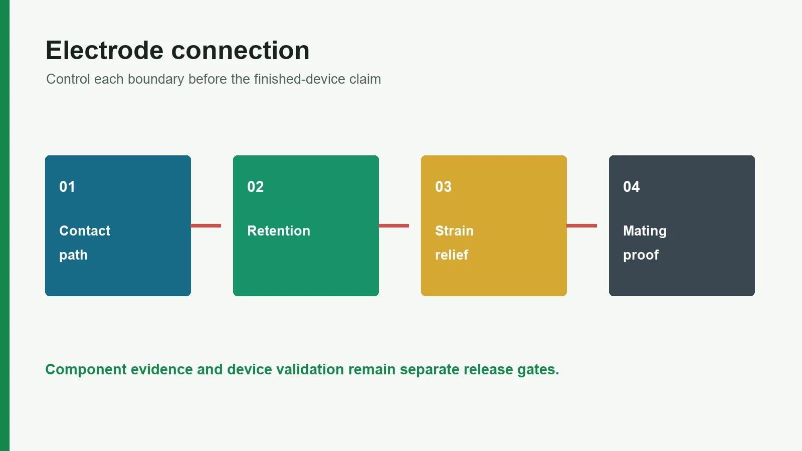
The medical device interface application page places these component decisions in the wider equipment program. The connector should be released only after its component evidence and device-level obligations are visibly separated.
11. Frequently Asked Questions
Which electrode pad connector type is best?
No electrode pad connector type is best in every application. A snap or tab supports detachable lead sets; an attached wire reduces electrode-end connection steps; a printed tail supports thin, multi-contact electronics integration. Choose after defining the mate, use sequence, load path, package, and validation owner.
Are ECG snap and tab electrodes interchangeable?
Not by default. A snap electrode needs a compatible socket, while a tab needs a compatible clip or grabber. A validated dual-interface electrode or adapter can support both, but the named lead, adapter, geometry, instructions, and verification must match the intended configuration.
Is every electrode snap connector the same size?
No. Public suppliers list several nominal snap categories, materials, and profiles. The controlled stud drawing and approved mating socket govern compatibility. A nominal diameter from a catalog or existing sample is not enough for tooling, retention-force limits, or alternate sourcing.
What should an electrode lead wire attachment drawing include?
It should include conductor preparation, attachment materials and geometry, wire specification, strain relief, cable exit, joint cross-section, inspection points, electrical test nodes, directional mechanical test, remote termination, and revision-controlled mating details. Applicable leadwire safety requirements belong in the device program.
What defines a printed electrode tail for a ZIF connector?
The mating connector defines contact pitch, exposed-pad geometry, contact side, finished tail thickness, insertion depth, stiffener, keep-outs, and cycle limit. ‘ZIF-compatible’ or ‘0.5 mm tail’ is incomplete without the manufacturer part number and controlled drawing.
Does fewer connector junctions guarantee better signal quality?
No. Reducing separable junctions can simplify the electrical path, but signal quality also depends on electrode chemistry, contact interface, trace design, motion, cable behavior, electronics, filtering, and use conditions. Finished-device tests must establish performance for the released construction.
Who validates an electrode connector used in a medical device?
Responsibility is shared but not interchangeable. Component suppliers validate their parts, the electrode manufacturer validates the quoted printing and attachment scope, and the legal device manufacturer integrates that evidence into finished-device verification, biological evaluation, risk management, labeling, and regulatory release.
Should the final pouch or tray be part of connector testing?
Yes, when packaging can load, crease, contaminate, or displace the connector zone. Test the production orientation, cable coil or tail route, compression state, conditioning, and unpack sequence. Package evidence should use acceptance limits derived from the finished-device risk and shelf-life plan.
12. Share the Mate and Cable-Use Conditions Next
Before requesting a manufacturability review, send the electrode drawing together with the mating stud/socket, clip, cable, FPC/ZIF connector, board, or recorder drawing. Include connection timing, expected cycles, cable routing, pull and bend conditions, package orientation, electrical test points, and finished-device validation owner. That package lets a manufacturer review the actual interface instead of guessing from a connector name.
JASPER can review printed electrode geometry, exposed contacts, snap or specified lead attachment, printed tails, reinforcement, conversion, and project-defined component inspection within an agreed quotation. It does not replace the device owner's patient-contact evaluation, essential-performance testing, risk management, clinical evidence, or regulatory release. To start the technical review, share the mating connector and cable-use conditions.
Technical References
- Source: FDA Use of ISO 10993-1 Biological Evaluation Guidance. Accessed 2026.
- Source: ISO 10993-1:2025 Biological Evaluation of Medical Devices. Accessed 2026.
- Source: ISO 14971:2019 Medical Device Risk Management. Accessed 2026.
- Source: FDA Design Control Guidance for Medical Device Manufacturers. Accessed 2026.
- Source: NHS Supply Chain. Accessed 2026.
- Source: Solventum. Accessed 2026.
- Source: Philips. Accessed 2026.
- Source: Scovill studs. Accessed 2026.
- Source: Scovill sockets. Accessed 2026.
- Source: FDA ECG guidance. Accessed 2026.
- Source: FDA EC12 recognition. Accessed 2026.
- Source: TE Connectivity. Accessed 2026.
- Source: Hirose. Accessed 2026.
- Source: IEC 60601-2-25:2011. Accessed 2026.
- Source: IEC 60601-2-27:2011. Accessed 2026.
- Source: IEC 60601-2-47:2012. Accessed 2026.
Release the connection and strain path together
Send the current drawing, material stack, electrode roles, connector, use conditions, acceptance methods, program phase, and annual volume.