
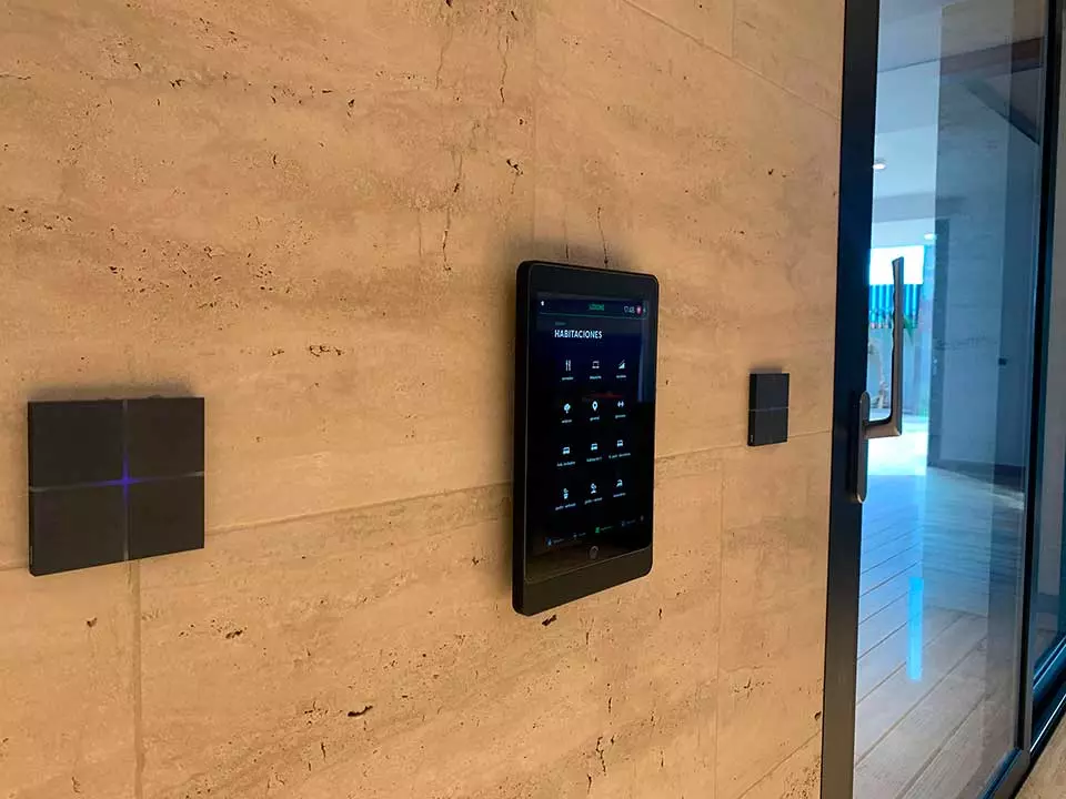
A smart-home capacitive touch panel should be specified as a complete interface stack, not selected by screen diagonal or faceplate appearance alone. For OEM engineers developing a KNX capacitive touch panel in the 4.3-inch class, the recommended path is to freeze the cover lens, sensor geometry, display, optical treatment, controller interface, wall-box envelope and validation conditions together. Custom capacitive touch panels suit sealed, low-profile controls with programmable icons. They are a poor default for safety-critical commands without an independent protective strategy, or for uncontrolled water exposure without defined false-touch and recovery criteria.
Quick decision table
| Project decision | Prefer this direction | Do not approve until |
|---|---|---|
| 4.3-inch display panel | Freeze active area, view area, outline and cutout separately | Display and touch drawings share a common datum system |
| Discrete wall switch | Use large electrodes and explicit light or sound feedback | Damp-finger operation and adjacent-key rejection pass on production-equivalent samples |
| Full touchscreen | Treat sensor, controller, display timing and host software as one subsystem | Coordinate accuracy, edge touch, wake and fault recovery are verified |
| Glass front | Use where cleanability, optical finish and scratch resistance lead the decision | Thickness, decoration, impact risk and touch tuning are validated together |
| Plastic or shaped front | Use where mass, impact behavior or geometry favors a polymer | Surface wear, chemical compatibility and dielectric variation are accepted |
| Wet-location interface | Define droplets, film, flow and cleaning liquids as separate conditions | False activation, intended wet touch and post-wipe recovery each meet written criteria |
| Networked wall controller | Budget active, display-off and networked-standby states separately | Wake, thermal and power tests use fixed network conditions |
A 4.3-inch KNX panel is a system stack, not a display size
A 4.3-inch designation identifies the nominal display diagonal, not the view area, lens outline, pixel count, interface, depth or wall cutout. NXP Semiconductors’ RK043FN66HS-CTG is one example: a 4.3-inch, 480 × 272-pixel TFT with LED backlight, capacitive touch and 24-bit RGB display input. Other modules differ. The released module drawing controls the mechanical design.
The KNX Association lists certified 4.3-inch touch-panel products and defines KNX TP devices as certified devices using dedicated twisted-pair media. KNX is the building-control side, not the local sensor-to-host interface. A panel may contain a touch controller, display controller, application MCU and KNX coupling unit with separate data paths and fault modes.
A typical smart-home display stack contains these layers from the room side inward:
- Cover lens: glass, PMMA, polycarbonate or a project-specific decorative material.
- Decoration: opaque border, dead-front ink, translucent icons, color layers and clear viewing window.
- Bond line: pressure-sensitive adhesive or optical adhesive, selected for the actual lens and sensor materials.
- Touch sensor: transparent electrodes on glass or film for a touchscreen, or PCB/film electrodes for discrete keys and sliders.
- Display and backlight: optional for a switch panel; mandatory for a graphical touchscreen.
- Flexible circuit and controller: routes sensor signals, interrupt, power and communications to the host.
- Carrier, gasket and wall interface: sets flatness, compression, grounding, service access and cosmetic alignment.
The Custom Capacitive Touch Panel Design Guide provides the broader drawing context. For a smart-home panel, add the wall-box package, building-bus boundary and power-state definition before releasing industrial-design surfaces.
Cover-lens material, thickness and decoration must be tuned with the sensor
Capacitive sensitivity depends on the full dielectric path. Infineon Technologies’ AN85951 lists relative permittivity ranges of 7.6–8.0 for standard glass, 2.9–3.0 for polycarbonate and 2.8 for acrylic in its CAPSENSE model; finger capacitance falls as overlay thickness rises. These are concept inputs. Controller, electrode, ground, adhesive and installed grounding determine the tuning window.
| Front-surface option | Engineering advantage | Main constraint | Drawing or test input |
|---|---|---|---|
| Flat glass | Stable cosmetic surface, crisp printing and a clean display window | Edge impact, weight, machining and decoration stack | Glass type, thickness, edge finish, holes, ink system and impact condition |
| PMMA | Low mass, machinability and optical clarity | Surface wear and chemical compatibility depend on grade and coating | Resin grade, coating, cleaner list, haze and scratch acceptance |
| Polycarbonate | Useful where impact behavior or shaped geometry leads | Optical finish, coating and dielectric range require control | Resin grade, texture, hard coat, molding tolerance and aging condition |
| Curved or 3D lens | Industrial-design freedom and a continuous decorative surface | Bond thickness, electrode-to-finger distance and stress vary across the shape | Surface data, local radii, section map and touch targets at worst-case geometry |
Infineon Technologies gives a 5 mm recommended maximum acrylic overlay for a button and 0.5 mm for a touchpad in one CAPSENSE widget table. They are platform examples, not universal limits. Microchip Technology likewise scopes mXT640U glass and plastic ranges to screen size, touch size and stack-up. “2 mm glass” alone does not define signal margin.
Avoid air pockets between the sensor and cover. A varying bond gap changes the dielectric path across the active area and can produce location-dependent touch response. Decoration matters as well: conductive or metallic pigments can disturb the field, and wide opaque borders can hide an electrode-to-icon alignment error until the backlight is energized. Freeze the ink stack, touch target, sensor artwork and bond process in the same revision-controlled stack drawing.
Apply the same coupling rules to Projected Capacitive Touch Panel Technology. Route shaped-fascia geometry into the electrode and bond review through Capacitive Touch Design for Curved and 3D Surfaces.
Wet-hand performance requires separate false-touch and intended-touch criteria
“Works with wet hands” is incomplete. A useful requirement identifies the liquid, amount, location, duration, grounding condition and expected panel behavior. A few isolated droplets, a damp fingertip, a conductive film joining two keys and a continuous stream are different electrical events. Cleaning spray and condensation add further patterns.
Infineon Technologies separates liquid-tolerance mechanisms in its CapSense guidance. A driven shield can reduce droplet false touches; a guard sensor can detect continuous flow and block other sensor outputs. This does not make the enclosure waterproof or prove valid touch through every film.
Write the wet-hand acceptance plan around four outcomes:
- Dry baseline: every enabled target operates at the specified touch location, including edge and corner positions.
- Liquid rejection: defined droplets or films do not issue unintended lighting, access, HVAC or scene commands.
- Intended wet touch: the project states which commands, if any, must remain available to a damp finger and how feedback confirms acceptance.
- Recovery: after liquid removal, the panel returns to normal operation within a project-defined interval without recalibration that masks a held finger.
Infineon Technologies AN85951 suggests 40 g of sodium chloride in 1 L of water as a platform stress liquid. It is not a universal smart-home standard. The OEM still needs tap water, cleaner, condensation and location-specific media.
Gloves are separate. Define material and thickness, then combine glove, liquid and electrical-noise tests; higher sensitivity can reduce water and noise margin.
Icon lighting needs an optical tolerance stack, not an LED callout
Backlit icons can leak through opaque fields, illuminate neighboring symbols, show LED hot spots or disappear in room light. The optical stack must connect lens print, translucent windows, diffuser or light guide, LED position, baffles, display opening and ambient target.
For discrete keys, specify off appearance, active and alarm colors, night behavior and feedback duration before LED selection. Control color and brightness with a signed golden sample and project limits; “white LED” does not control bin variation, ink transmission or assembly gap.
For a smart-home capacitive touchscreen, decide whether the display is air-bonded or optically bonded and define the inactive black appearance beside printed dead-front areas. The cover window, display polarizer and backlight form one optical stack. Backlight dimming also belongs in the electrical specification because it affects active power, thermal rise, low-light readability and visible PWM artifacts.
Verify established function symbols in the International Electrotechnical Commission IEC 60417 / International Organization for Standardization ISO 7000 database. Custom icons still need controlled artwork, print-process feature checks and rules for vertical and horizontal variants.
Wall-box packaging, power states and interfaces must be frozen before tooling
The rear package controls installation and service. A wall-box drawing must show envelope, screw pattern, conductor entry, connector access, bend radius, mains keep-out, grounding and removal direction. “Fits a United States one-gang box” or “fits an EU box” is insufficient because depth, conductor fill and walls vary.
Wall-box constraints
Separate the touch/display low-voltage region from any mains switching or power-conversion region according to the product safety architecture. Keep hot components away from the touch controller’s baseline-sensitive area and from temperature sensors used for room control. Show the installed orientation of vents, gaskets and antennas. If the face assembly clips onto a power base, define the safe state when the face is removed and the service method for restoring configuration.
Define flatness and gasket compression. Excess compression can bow the sensor; too little can open a light or ingress path. Verify fastening loads on the installed assembly.
Standby power is a set of modes
Measure four states: display active, dimmed, display off but locally responsive, and networked standby with intended communications enabled. Record supply voltage, network, screen content, ambient behavior, wake source and stability. Also test update, network-search and backlight faults.
International Electrotechnical Commission IEC 62301:2026 covers non-active modes other than networked standby; IEC 63474:2026 covers networked standby for edge equipment. Neither sets a watt limit. The requirement must define the limit, mode and measurement boundary, including KNX TP and auxiliary inputs.
Keep the three interface layers distinct
Touch, display and building-automation interfaces are separate. The NXP Semiconductors example uses 24-bit RGB; Microchip Technology mXT640U uses an Inter-Integrated Circuit (I2C) host interface and interrupt. Confirm logic levels, bus speed, reset, interrupt polarity, firmware configuration, diagnostics and behavior when the host stops reading events.
KNX TP, KNX IP and KNX RF are building-network media, not the local touch bus. A marked device needs the applicable KNX Association certification and ETS behavior. For a USB touch-to-host link, review enumeration, power, ESD and recovery in USB Interface Design for Capacitive Touch Panels.
National Institute of Standards and Technology NISTIR 8259A provides a starting security set: device identification, authorized configuration, data protection, interface access, software update and cybersecurity-state awareness. The RFQ should assign provisioning, rollback, debug-port state and support ownership.
The application-risk matrix should drive sensor and validation choices
| Application condition | Dominant failure path | Design control | Required verification |
|---|---|---|---|
| Kitchen backsplash or utility area | Droplets bridge keys or cleaning film shifts baseline | Shield/guard strategy, spaced commands, cleanable lens, command confirmation where needed | Droplet, damp-finger, cleaner-film, wipe and recovery sequence |
| Bathroom or entry near condensation | Surface film plus grounded user changes coupling | Condensation profile, gasket path, conservative wake/touch logic | Temperature/humidity transition on installed assembly, then touch map |
| Bedroom or hallway at night | Icons too bright, too dim or visually inconsistent | Night-state luminance, ambient sensing policy, controlled LED/ink stack | Dark-room state transitions, wake latency and uniformity on golden sample |
| Mains-connected wall switch | Limited box volume, heat and electrical segregation | Defined rear envelope, power architecture, clear safety classification | Thermal, abnormal, dielectric/spacing and installation review under applicable product standard |
| HVAC or appliance safety-related command | Missed or false touch affects protected operation | Independent protective logic, command confirmation or physical alternative | End-equipment hazard analysis and safety-function fault testing |
| Curved decorative fascia | Variable electrode distance and bond stress | Geometry-aware sensor, controlled bond line, local datum map | Full-surface touch map after environmental conditioning |
| Wi-Fi, Thread or other radio-equipped panel | Radio traffic raises power or creates touch/display noise | Antenna keep-out, power-state logic, EMC layout and firmware diagnostics | Radio active/idle EMC, coexistence, network-loss and Federal Communications Commission authorization review |
Validation must use production-equivalent stacks and end-equipment conditions
Validation should progress from sensor coupons to complete panels and installed equipment. Only a production-equivalent assembly exposes frame grounding, wall-box stress, converter noise and connector interactions.
| Validation block | Minimum inputs | Pass evidence |
|---|---|---|
| Geometry and cosmetics | Released lens, sensor, display and housing drawings; datum and tolerance stack | Dimensional report, approved appearance sample, no view-area or icon misregistration |
| Touch function | Complete touch map, finger targets, gloves, orientation, wake state and response criteria | Raw-data/tuning record plus functional results on multiple production-equivalent samples |
| Liquid behavior | Named liquids, dose/application method, dwell, flow, allowed commands and recovery time | No prohibited command; required wet touches and recovery meet the written protocol |
| Optical performance | Ambient states, icon/display content, dimming states, color and leakage criteria | Measured record and approved golden sample under controlled viewing conditions |
| Power and thermal | Supply boundaries, network state, brightness, wake source and software build | Active/non-active/networked-state log, wake time and installed thermal results |
| EMC and ESD | Product class, ports, cables, mounting, test plan and performance criteria | Accredited or qualified-lab report with software version and post-test functional check |
| Environmental and cleaning | Temperature/humidity profiles, cleaners, cycles and installed compression | Touch, appearance, bond and sealing checks before/during/after conditioning |
| Firmware and network | Provisioning, loss of network, update interruption, rollback, reset and diagnostics | Recovery record with no unsafe command or unrecoverable configuration loss |
Product classification selects standards. International Electrotechnical Commission IEC 60669-2-1:2021 covers electronic control devices, including HBES/BACS switches, within its scope. IEC 60730-1:2022 addresses controls whose performance can impair household-equipment safety. IEC 60529 classifies enclosure protection; an IP claim belongs to the tested assembly. IEC 61000-4-2:2025 defines ESD methods while the product plan selects severity. A United States radio design also needs current 47 CFR Part 15 classification and authorization review.
Build those decisions into testing and validation planning before design verification. Use prototyping and sample approval to lock separate electrical, cosmetic and optical evidence rather than asking one early sample to represent every production process.
Capacitive touch is not suitable for every household control
Choose a mechanical control, guarded command or redundant interface when users need positive passive tactile confirmation, when loss or false activation can create an unacceptable hazard, or when the front material is conductive and cannot be isolated from the sensing field. Capacitive touch is also a weak choice when uncontrolled liquid films must coexist with unrestricted commands, or when the product cannot support controller tuning after the final enclosure, display and power electronics are installed.
Accessibility can change the decision. Feedback confirms an accepted command but does not create a physical landmark. Evaluate intended users and provide an alternative path for essential functions when required.
Frequently asked questions
What does “KNX capacitive touch panel 4.3” mean?
It means a KNX-connected wall controller with a nominal 4.3-inch display and capacitive touch. It does not specify resolution, active area, lens size, mounting box, local touch bus or KNX medium. Identify the module drawing, KNX TP/IP/RF architecture, power inputs and ETS requirements.
Can a capacitive touch wall switch work with wet hands?
Yes, for defined wet conditions with suitable sensor, shield or guard architecture and firmware. Separate damp-finger detection from rejection of droplets, conductive films and flow. A dry touch test or IEC 60529 enclosure test does not prove wet-hand behavior; test intended touch and false commands directly.
Is glass or plastic better for a smart-home capacitive touch panel?
Neither is universally better. Glass favors optical finish and surface wear; PMMA or polycarbonate can favor mass, impact behavior or shaped geometry. Coupling depends on permittivity, thickness, electrode size and bonding, so validate the final decorated lens with the selected controller.
What is the difference between a capacitive touch switch and a capacitive touchscreen?
A capacitive touch switch uses discrete electrodes for fixed functions. A touchscreen uses a matrix to report positions and gestures over a display. The touchscreen adds coordinate accuracy, display timing, optical bonding and host-software dependencies; the switch emphasizes icon alignment and unambiguous feedback.
Does a 4.3-inch KNX touch panel connect directly to the KNX bus?
Some finished panels integrate KNX coupling; a display-and-sensor stack usually does not. The touch controller may use Inter-Integrated Circuit (I2C), SPI or USB while the host handles KNX TP, IP or RF. Define isolation, power, commissioning, ETS data and KNX Association certification ownership.
How should standby power be specified for a networked wall panel?
Set separate limits for active, dimmed, display-off responsive and networked-standby states. Record input boundary, supply, networks, screen content, ambient response and wake source. International Electrotechnical Commission IEC 62301:2026 covers non-active modes; IEC 63474:2026 addresses networked standby. Neither supplies the watt limit.
What files should accompany a custom capacitive touch-panel RFQ?
Provide lens and housing drawings, active/view areas, display and sensor data, stack-up, decoration, FPC and connector, interface, wall-box envelope, power modes, environment, wet-hand criteria, optical states, markets, sample quantities and acceptance tests. Native CAD plus dimensioned PDFs reduces ambiguity.
Can capacitive touch be used for a safety-critical household-equipment command?
Only after the hazard analysis defines the safety function, fault response and standard. A visual button alone should not be the protective measure. International Electrotechnical Commission IEC 60730-1 addresses controls whose performance can affect equipment safety; independent protection or a physical alternative may still be required.
Project-input checklist for engineering review
Before requesting design review, assemble these inputs:
- Active area, viewing area, lens outline, corner radii, holes, cutouts and mounting datum.
- Cover-lens material, grade, thickness, coating, texture, edge finish and approved cleaners.
- Display part number, resolution, interface, brightness states, viewing direction and FPC drawing.
- Touch technology, sensor construction, electrode targets, controller preference and host interface.
- Decoration artwork, ink stack, dead-front behavior, icon colors and day/night optical criteria.
- Wall-box type and drawing, rear keep-out, conductor entry, power architecture, grounding and service method.
- KNX medium, ETS scope, network interfaces, security/update ownership and diagnostic access.
- Dry, glove, wet-hand, droplet, film, continuous-flow and recovery acceptance criteria.
- Launch markets, preliminary IEC 60669-2-1, IEC 60730-1 or UL 60730-1 classification, EMC/ESD, ingress, environmental and safety plan.
- Prototype stages, sample quantities, golden-sample ownership and drawing/change-control process.
Use the completed package to send drawings for engineering review. Include the active area, cover lens, display stack, interface and operating environment so the review can address coupled risks rather than quote an isolated component. When the technical boundary is stable, request an engineering quote.
References
- KNX Association, GRTP43D-Jxx-KNX certified-device record, accessed August 24, 2026.
- KNX Association, KNX Technology, accessed August 24, 2026.
- NXP Semiconductors, RK043FN66HS-CTG 4.3-inch LCD panel, Rev. 1, February 10, 2022.
- Infineon Technologies, AN85951 CAPSENSE Design Guide, accessed August 24, 2026.
- Infineon Technologies, AN66271 CapSense Design Guide, Rev. H.
- Microchip Technology, mXT640U Datasheet, 10046FX, April 2016.
- International Electrotechnical Commission, IEC 60669-2-1:2021, published February 5, 2021.
- International Electrotechnical Commission, IEC 60529 consolidated version, Edition 2.2.
- International Electrotechnical Commission, IEC 61000-4-2:2025, published March 7, 2025.
- International Electrotechnical Commission, IEC 62301:2026 and IEC 63474:2026, published May 22 and June 9, 2026.
- International Electrotechnical Commission, IEC 60730-1:2022, published September 19, 2022.
- National Institute of Standards and Technology, NISTIR 8259A: IoT Device Cybersecurity Capability Core Baseline, May 2020.
- Government Publishing Office, 47 CFR Part 15 — Radio Frequency Devices, 2023 edition; verify the current eCFR at launch.
- IEC and ISO, Graphical Symbols for Use on Equipment, accessed August 24, 2026.
- UL Solutions, IEC/UL 60730-1 6th Edition Standard, accessed August 24, 2026.
JASPER provides custom touch-sensor, cover-lens, display-stack and controller-interface integration for the specified project.
Bring the drawing, stack and operating conditions
JASPER engineering will review the interfaces, open risks and evidence required for a production quote.