
Set the layout from the real operator and task: define the glove or tool, viewing envelope, cleaning method, key consequence, active area, spacing, legends, and sample evidence before the artwork and tooling are released.
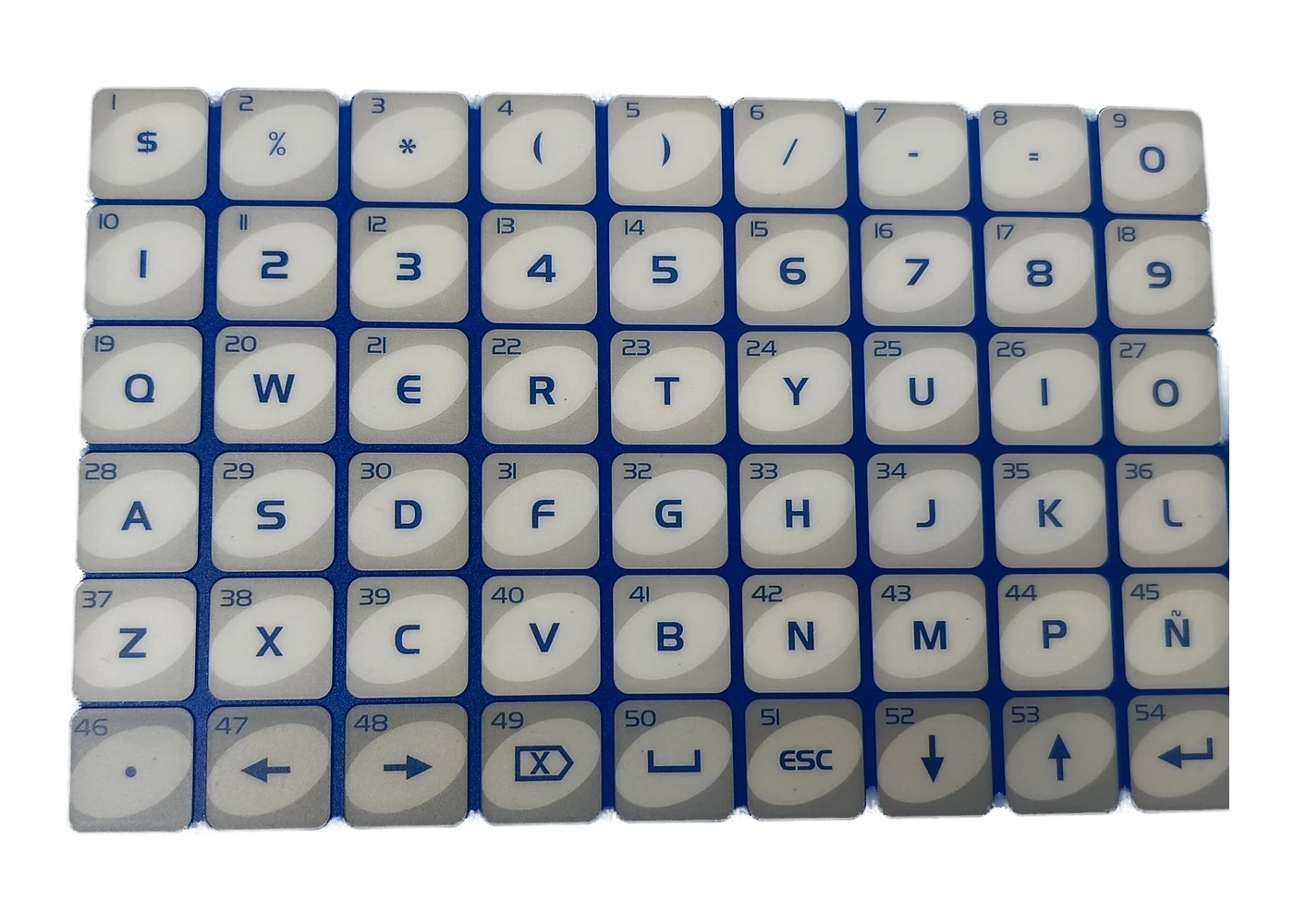
Membrane keypad usability fails more often from layout mistakes than from exotic material choices. A panel can use sound polyester, solid metal domes, and a clean matrix circuit and still force wrong presses, slow cycles, or unreadable labels once it leaves the lab. This guide is for OEM engineers and HMI owners specifying membrane keypads for industrial, medical-adjacent equipment panels, marine, and instrument products across North America, Europe, and Asia export programs. It is not a supplier shortlist and not a full stack-up recipe. The practical CTA at the end is simple: send the key map and the operator-use conditions before tooling freezes.
This article was prepared with input from JASPER, a membrane switch and keypad manufacturer. Where a manufacturer engineering review helps, that is stated. Public keypad guides often concentrate on construction and materials; this page stays with the operator and layout decisions that must be resolved before the stack is released.
1. Why membrane keypad layout design fails after the prototype looks fine
Membrane keypad layout design looks finished in a CAD screenshot: neat rows, brand colors, icons that match the GUI. Field use is different. Operators approach from an angle. Hands carry oil or nitrile gloves. Cleaners attack ink edges. Critical stop functions sit next to high-frequency keys. Lighting swings from warehouse sodium lamps to outdoor glare. None of that shows up if the only review criteria were “fits the cutout” and “matches the brand deck.”
Human-factors standards exist because controls are not pure graphics. The International Organization for Standardization places physical input devices in the ISO 9241 family, including ISO 9241-410:2008. Equipment programs may also reference the United States Department of Defense MIL-STD-1472 human-engineering criteria. Human Factors and Ergonomics Society workstation guidance is useful context for seated keyboards, yet it is not a drop-in law for a vertical machine panel. These references do not provide one universal millimetre for every membrane keypad. They establish the right question order: who acts on the control, under what conditions, and with what error cost.
When layout is late, cost shows up as silent scrap rather than a dramatic recall headline. Common patterns:
- Keys sized from a bare-finger artwork review, then used with production gloves.
- Legends approved under one lighting angle, then shadowed by the installed bezel.
- Emergency or mode keys placed by GUI order instead of task and risk order.
- Dense grids released without measuring adjacent-key errors in the real task.
- Flat cosmetics chosen for wipe-down even though eyes-off tasks need tactile location cues.
Cleaning multiplies weak layouts. The International Electrotechnical Commission publishes IEC 60529 for enclosure protection against dust and water; an IP code describes the evaluated enclosure configuration, not an art style. A required IP target does not correct poor key spacing, while washdown and chemical-wipe routines still punish open edges, worn low-contrast legends, and emboss geometries that trap residue. Layout and sealing have to be reviewed together. Underwriters Laboratories flammability language such as UL 94 is a material topic, not a layout shortcut, although it may appear in the same controlled drawing package.
The rest of this guide turns those failure modes into a 10-point evaluation framework, a step process from key map to first article, and a red-flag list that should stop a layout freeze.
2. The 10-point evaluation framework for membrane keypad layout design
Use these criteria in roughly this order. Operator profile and task risk outweigh decorative alignment. Manufacturing limits (criterion 10) can veto an otherwise pretty map.
2.1 Operator profile and task model
Start with who presses the keys, how often, and what a wrong press costs. A laboratory instrument used by trained staff for setup menus is not the same as a warehouse HMI used in motion with gloves. A cold marine panel with wet gloves is not a clinic cart cleaned between uses. Note one-hand vs two-hand use, standing vs seated posture, and whether the task is eyes-on or eyes-off. Frequency matters: a production-cycle key deserves different placement from a service-only control.
A one-page operator profile listing the actual glove or tool, duty cycle, error cost classes (nuisance / rework / safety), and mounting posture.
“General industrial use” with no glove, light, or error-cost notes attached to the key map.
2.2 Membrane keypad key spacing and touch-target size
Membrane keypad key spacing is the center-to-center pitch plus the active area that actually closes the switch. Desktop keyboard norms (for example, traditions discussed alongside ANSI/HFES 100 workstation guidance) are a poor copy-paste source for industrial membranes. Membrane keys share a flat stack, metal or polydome travel is short, and operators often wear gloves.
No standards citation or catalog table can replace the production hand condition, active circuit area, spacer opening, adjacent-key risk, and enclosure support. Use the decision matrix below to generate candidate layouts, then measure the candidates on the production-intent assembly.
| Operator condition | Define on the drawing | Prototype check | Release evidence |
|---|---|---|---|
| Bare finger, precision task | Active area, pitch, edge clearance | Reach and adjacent-key trial | Approved key map and error log |
| Bare finger, industrial task | Frequency and consequence by key | Repeated task in installed posture | Task completion and key-ID record |
| Thin production glove | Exact glove model and size | Center and edge presses | Glove-specific trial result |
| Heavy, double, or cold-work glove | Worst intended glove stack | Adjacent-key and safety-key trial | Signed exception or revised spacing |
| Stylus, probe, or assistive tool | Tip geometry and allowed approach | Off-axis and edge actuation | Tool-specific acceptance record |
Pitch and active area called out on the drawing with glove class and a note that first-article includes timed task trials.
Pitch justified only by “GUI button size on the LCD mockup.”
2.3 Control keypad legends hierarchy and contrast
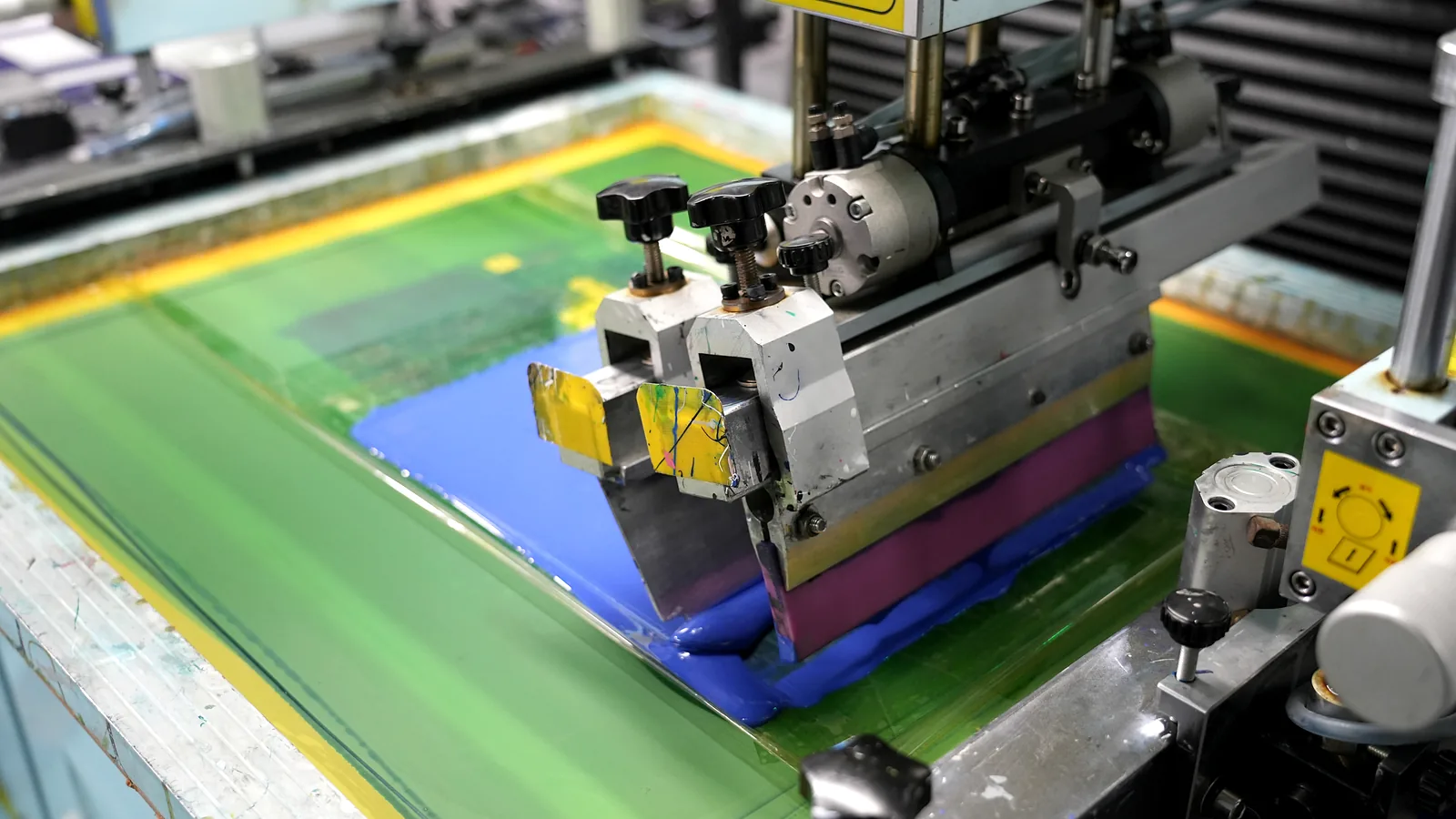
Control keypad legends carry mode, risk, and brand meaning. Hierarchy means primary actions read first, secondary actions second, and service keys last. Contrast must survive the lighting plan and the cleaning chemistry. The International Organization for Standardization maintains ISO 7000 graphical symbols, while the International Electrotechnical Commission maintains the IEC 60417 database. Use the applicable symbol source when the operator population is multilingual; word legends still need a language plan and a readable size for the installed viewing distance.
| Legend method | Strength | Weakness | Better when… |
|---|---|---|---|
| Screen-printed ink on rear of overlay | Durable, opaque colors | Art changes need new screens | Stable high-volume colors |
| Digital print | Fast art revisions | Durability depends on ink/overlay system | Prototypes and frequent SKU art |
| Selective texture / matte-gloss split | Finger cues without color | Weak for color-blind risk coding alone | Eyes-off industrial panels |
| Deadfront (hidden until lit) | Clean idle face, status on demand | Needs backlight design | Status legends, night modes |
| Embossed outline only | Tactile find | Poor for first-time users without training | Trained operators, dark environments |
Legend schedule table: key ID, primary text/symbol source (e.g., IEC 60417 reference), color, height, and risk class.
Rainbow icons with no contrast check and no symbol standard reference.
2.4 Key grouping, modes, and error-critical separation
Group keys by task, not only by electrical matrix convenience. Start / stop / reset clusters should match the mental model of the machine. Separate destructive or safety-related keys from high-frequency jog keys with dead space, size change, or shape change. Mode keys that change the meaning of a whole row need clear latch feedback (LED window, host UI, or both).
Zones labeled on the key map: Run, Setup, Service, Safety. Minimum gap called out between Safety and Run.
Emergency or “delete recipe” control sharing the same pitch grid as numeric entry with no buffer.
2.5 Viewing angle, mounting height, and light
Membrane keypad usability collapses when legends are designed for dead-on lab photos. Record mounting height, typical eye position, indoor vs outdoor use, and whether a hood or direct light will hit the surface. Glossy PET overlays can produce glare; matte hard-coated finishes change reflected light and printed color appearance. Emboss can also shadow nearby text at an oblique angle. Build an installed viewing envelope, then approve legend baselines and icon orientation from its boundary positions rather than from one studio photograph.
Viewing envelope sketch (plan + side) attached to the artwork package, with lux notes if known.
Artwork approved only from a perpendicular render with studio lighting.
2.6 Gloves, tools, and actuation force mapping
Gloves change reach, contact location, perceived feedback, and the force an operator can distinguish. Metal dome candidates have part-specific force and snap characteristics; the installed overlay, emboss, spacer, actuator, vent path, and support surface change the result. Polydome and flat-contact stacks behave differently again. If operators use a stylus, rings, or an assistive device, the active area and emboss shape may change. Document the worst intended hand covering and compare candidate constructions on the actual support.
An approved force/feedback window tied to a named dome or contact construction, measurement method, support fixture, and real glove trial.
Force chosen only from a catalog “standard dome” with no operator covering note.
2.7 Cleaning, washdown, and sealed-edge constraints
Cleaning chemistry and water jets are layout constraints. Hard-to-clean pockets form between emboss features and raised bezels. Window cutouts for LCDs or TFT modules create edges that must seal with a qualified gasket, adhesive, or both. IEC 60529 IP targets belong to the evaluated assembly, not the art layer alone. Layout choices still help or fight the seal path: continuous borders, controlled openings, and legend systems qualified against the project's actual cleaner list.
Cleaner list, required IP code, test configuration, and edge-seal concept on the same review sheet as the key map.
Open indicator holes scattered through the keypad field on a washdown machine with no sealing story.
2.8 Emboss and tactile map vs flat legend zones
Emboss is part of layout, not a cosmetic extra. Pillow, rim, or dome emboss can help finger location without eyes. Flat zones are easier to wipe and may suit instruction or display areas. Mixed maps are often useful: tactile location cues for operating keys and flat construction for large printed zones. Emboss height, radius, edge distance, film grade, forming process, and dome relationship must be reviewed as one tool-and-material decision, then approved with the intended glove and cleaner.
Emboss drawing with heights, radii, and keep-out from edges and windows.
“Emboss everywhere” on a panel that requires frequent controlled cleaning.
2.9 Deadfront, backlight, and status-legend coordination
If status text should appear only when active, deadfront construction and LED or LGF backlight paths must be planned with the key map. Random LED holes without optical design create hot spots and wash out nearby control keypad legends. Backlight also changes perceived contrast: a legend that passes in daylight can disappear when the panel is lit from behind with the wrong color.
Optical stack note per illuminated key or window, with day/night contrast checks.
LEDs dropped into the matrix only because the schematic had spare GPIOs.
2.10 Circuit matrix, connector, and DFM limits on dense layouts
Electrical reality ends bad art. Row/column matrices prefer traceable key maps; highly irregular decorative layouts can increase routing, ghosting risk, and test complexity. Tail exit direction, bend radius, connector orientation, circuit technology, crossover strategy, and edge seals constrain key placement. The IPC-2221 printed-board design domain provides useful circuit-design context, but the qualified line/space, dielectric, print, and registration rules must come from the selected membrane-circuit process. Ask for a DFM mark-up before tooling.
Manufacturer DFM redlines on pitch, tail, and emboss keep-outs before steel rule dies are cut.
Marketing-approved art locked while the circuit layer is “to be determined.”
3. Step-by-step process: from key map to first-article layout
This sequence turns the framework into a buyer/engineering process. Skip steps and the first-article becomes a debate, not a measurement.
Step 1 — Freeze the functional key list, not the art
List every key with function ID, risk class, frequency class, and whether it is momentary or maintained. Remove decorative keys that do not map to firmware. Assign provisional groups: Run, Setup, Service, Safety.
Step 2 — Write operator-use conditions on one page
Capture glove type, tool use, mounting height, viewing angles, light, cleaning chemicals, temperature range, and whether the task is eyes-off. This page travels with the RFQ. Without it, membrane keypad key spacing is guesswork.
Step 3 — Draft pitch, active area, and separation rules
Apply the decision matrix in §2.2. Add deliberate separation for consequence-critical keys. If the panel is for industrial control equipment, start with the documented production hand condition rather than a bare-finger artwork assumption.
Step 4 — Build the legend schedule
For each key: text and/or ISO 7000 / IEC 60417 symbol, language, color, minimum height, and deadfront yes/no. Check contrast against the real overlay finish (gloss vs anti-glare).
Step 5 — Overlay emboss / flat map and backlight plan
Mark emboss types per key. Place LED windows or light-guide zones only where firmware will drive status. Keep optical keep-outs away from critical text.
Step 6 — Manufacturer DFM and circuit routing review
Send the package for an engineering review of pitch feasibility, tail exit, adhesive borders, emboss tooling, and matrix routing. Expect marked-up questions. A useful review challenges unsupported density and identifies what the first article must prove rather than silently quoting incomplete artwork.
Step 7 — First-article trials with real hands and cleaners
Test with the specified gloves, mounting angle, and ambient light. Time a standard task. Run the cleaner wipe protocol on legend samples. Record miss rates and illegible keys. Only then release production artwork.
Project input checklist (send with the key map)
| Input | Why it matters |
|---|---|
| Key list with risk/frequency class | Drives size and separation |
| Operator glove / tool note | Drives pitch and force |
| Mounting drawing + eye position | Drives legend size and gloss |
| Light conditions (day/night/outdoor) | Drives contrast and deadfront |
| Cleaning chemistry + IP target | Drives edge and emboss choices |
| Language / symbol standard | Drives control keypad legends |
| Host UI mode behavior | Drives mode-key feedback |
| Tail exit and connector constraints | Drives edge keep-outs |
| Backlight / LED wish list | Drives optical stack |
| Environmental range (°C, humidity) | Drives material and adhesive notes |
Standards quick-reference (layout package shelf)
| Document | Why it sits next to the key map |
|---|---|
| ISO 9241-410:2008 | Physical input device ergonomics framing |
| MIL-STD-1472 | Human-engineering criteria for equipment programs |
| IEC 60529 | IP Code language for evaluated enclosure protection |
| ISO 7000 / IEC 60417 | Equipment symbol libraries for legends |
| IPC-2221 design domain | Circuit spacing context under dense key grids |
| ANSI/HFES 100 | Desktop workstation contrast—not a membrane pitch law |
| UL 94 | Overlay polymer flammability class on the material callout |
Use the table as a review checklist, not as a claim that every keypad must be certified to every row.
4. Release blockers that should stop a layout freeze
These override attractive renders.
- No operator-use sheet — pitch and legends cannot be validated.
- Pitch copied from the GUI pixel grid — screens are not fingers.
- Safety keys inside the same dense grid as numeric entry — adjacent-key risk.
- Low-contrast gray-on-gray icons for outdoor or low light — unreadable legends.
- Washdown IP claim with scattered unsealed holes in the keypad field — sealing conflict.
- Art locked before DFM — tooling rework and scrap.
- One force band for bare hand and winter gloves — inconsistent actuation.
- Deadfront status text without optical design — hot spots and washed legends.
- “Universal layout” reused across glove and bare-finger products without retest — silent field failures.
- Language-only legends for multi-country equipment with no ISO 7000 / IEC 60417 plan — training debt.
If two or more release blockers appear, reopen the key map. Do not buy time with a firmware-only patch for a physical miss-hit problem.
5. Frequently Asked Questions
What is membrane keypad layout design?
Membrane keypad layout design is the specification of key positions, sizes, spacing, grouping, legends, and tactile/optical cues on a membrane keypad so operators can act under real lighting, glove, and cleaning conditions. It sits above pure graphic styling and beside electrical matrix design.
How much membrane keypad key spacing do gloved operators need?
There is no single global millimetre. Define the active circuit area, pitch, edge clearance, adjacent-key consequence, glove or tool, and mounting posture together. Compare candidate layouts with the real glove on a production-intent panel, then release the measured layout and acceptance record.
What makes good control keypad legends?
Good control keypad legends use a clear hierarchy, durable contrast, and symbols from libraries such as ISO 7000 or IEC 60417 when language varies. Primary actions should out-read service keys. Deadfront and backlight need their own optical plan.
Is desktop keyboard pitch valid on a membrane keypad?
Usually no. Desktop workstation guidance (including traditions around ANSI/HFES 100) targets different travel, force, and hand posture. Membrane stacks are thin, often gloved, and mounted at machine angles. Use membrane-specific trials.
How do cleaning and IP ratings affect layout?
IEC 60529 IP ratings apply to the assembled enclosure path. Layout still matters: emboss pockets, open LED holes, and weak borders fight washdown. Put cleaner lists and seal concepts on the same review as the key map.
Should every key be embossed?
No. Emboss can help eyes-off find and gloved location, while flat zones are easier to wipe and suit some instruction or display areas. Mix emboss by task, then confirm the height, radius, film, tooling, dome relationship, and cleaning result on production-intent samples.
When is a dense compact layout the wrong choice?
When operators wear thick gloves, when keys are safety-critical, when viewing angles are extreme, or when cleaning demands large wipe surfaces. Dense maps also stress circuit DFM. Compact consumer remotes and gloved outdoor machines are different problems.
What files should go to a manufacturer for layout review?
Key map with IDs, operator-use conditions, legend schedule, mounting drawing, environmental and cleaning notes, connector/tail constraints, and backlight wishes. Ask for DFM redlines before tooling.
Does JASPER only sell finished keypads or also review layouts?
JASPER manufactures custom membrane keypads and related HMI parts and can review a layout package before tooling. The useful output is a marked-up key map, open-decision list, and sample plan, not an unqualified approval of the artwork.
How does membrane keypad usability get measured at first article?
Run timed tasks with the real glove and mounting angle, count adjacent-key errors, check legend readability at the design viewing envelope, and wipe sample legends with the specified cleaner. Record failures against key IDs, not only pass/fail cosmetics.
6. What to do next
Lock membrane keypad layout design with written operator conditions, a pitch and active-area table, a legend schedule, and a DFM pass before dies are cut. If the map is ready, send the key map and operator-use conditions for an engineering review. Keep ISO 9241-410, MIL-STD-1472, IEC 60529, ISO 7000, IEC 60417, and IPC-2221 on the reference shelf while project dimensions are resolved on the drawing. Layout is a human-factors and manufacturing decision, not last-mile art polish.
Review the key map before artwork and tooling are released
Send the key IDs, operator glove or tool, viewing envelope, mounting drawing, legend schedule, cleaning conditions, tail direction, and sample priorities. JASPER Engineering will mark the layout decisions that need evidence.