
Waterproof membrane switch sealing belongs to the complete mounted assembly. Define the liquid exposure, map every path into the circuit, freeze the test article, and require evidence for the exact perimeter, windows, vent, tail, connector, and enclosure state being supplied.
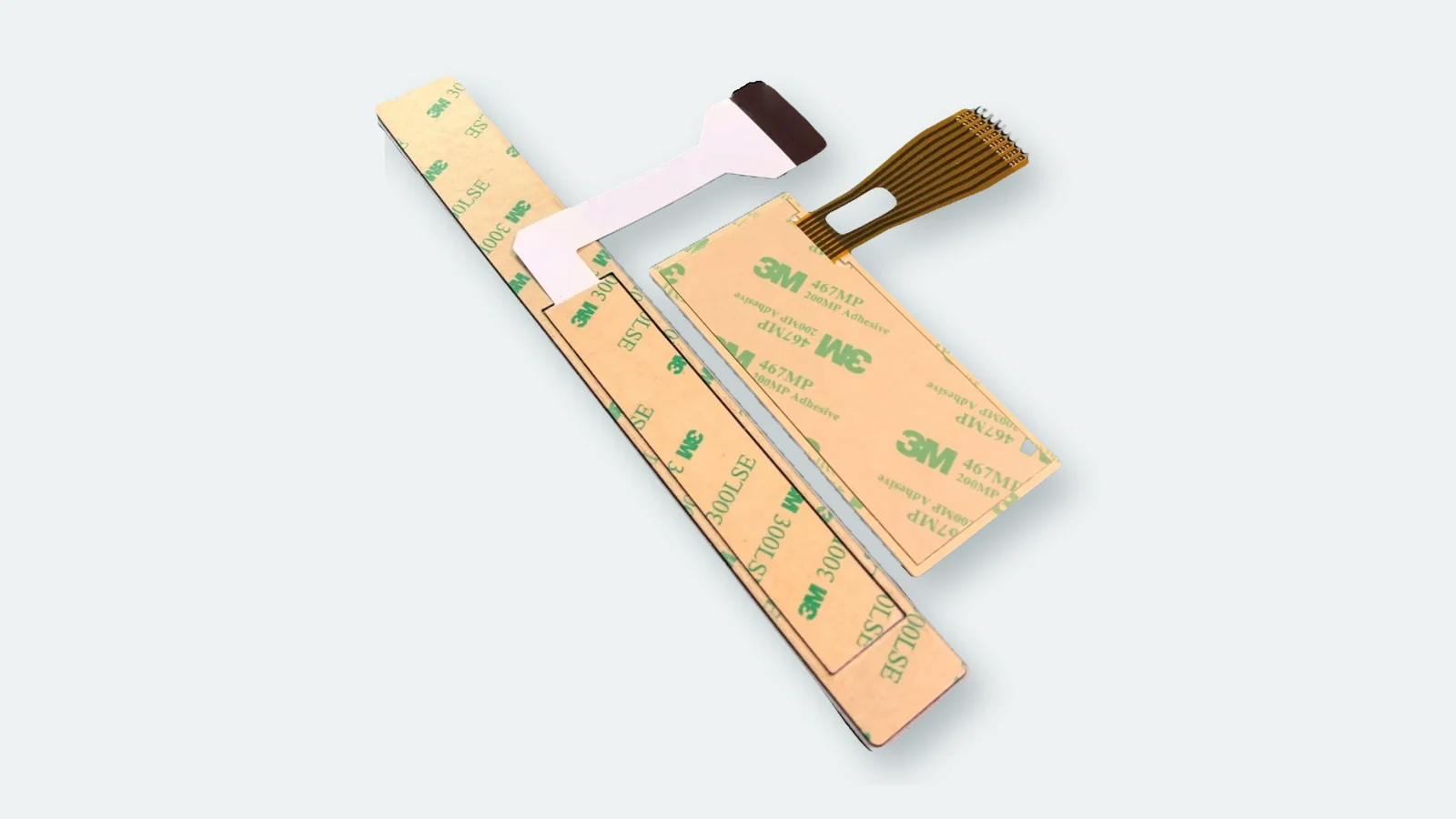
A waterproof membrane switch can still leak through a perfect front film. The usual question is not whether polyester absorbs water; it is whether liquid can move around an edge, under a window bond, through a vent, along a flexible tail, or into an unsealed rear cavity. That is why the target IP code must be reviewed against the complete mounted assembly.
This guide gives OEM mechanical, electronics, and quality teams a practical way to review waterproof membrane switch sealing before tooling or validation. It supports the waterproof membrane switch product page with an engineering framework: define the test article, map nine ingress paths, compare jet and immersion loads, and request evidence that belongs to the production revision. JASPER Engineering can review that package when the enclosure drawing, interface stack, and exposure conditions are available.
1. Start with the test article, not the IP label
IEC 60529 is titled Degrees of protection provided by enclosures (IP Code). That wording sets the boundary. A loose graphic overlay, an adhesive coupon, or an unmounted membrane switch is not automatically the same article as a finished control panel with a bezel, display window, tail slot, connector, screws, and rear cover.
An IP65 or IP67 statement is useful only when the evidence identifies what was assembled and how it was evaluated. The first digit and second digit describe separate protection characteristics. The water methods represented by the second digit also create different loads. A temporary-immersion result does not document directed-water performance unless both exposures were actually included, and a jet result does not document an immersion boundary.
Before discussing film grade or gasket type, record these seven items:
| Review input | What must be defined | Why it changes the result |
|---|---|---|
| Exposure | Rain, directed water, temporary immersion, cleaning liquid, condensation, or a combination | Each exposure loads a different path |
| Test article | Full enclosure, representative fixture, or component sample | Evidence applies to the tested configuration |
| Mounting state | Adhesive, gasket, fasteners, torque procedure, and substrate | Compression and flatness can open or close the perimeter |
| Openings | Display windows, LEDs, vents, hardware, speakers, and cable exits | Every opening creates another boundary |
| Rear state | Tail treatment, connector mating, rear cover, and cavity seal | Immersion often reaches the assembly from behind |
| Conditioning | Cleaning, thermal cycling, UV, vibration, or other project preconditioning | A new seal and an aged seal may behave differently |
| Acceptance | Visual, electrical, insulation, functional, and internal moisture checks | “No visible leak” may miss circuit contamination |
Decision rule: use the IP designation as the name of a controlled validation method, never as a substitute for the assembly drawing.
2. The nine waterproof membrane switch sealing paths
The path map below is the fastest way to find missing ownership. Each row is a route from the wet side to a sensitive electrical region. The drawing package should name an owner and evidence for all nine, even when the final decision is that a path is outside the wet boundary.
| Path | Boundary under review | Typical failure mechanism | Evidence expected before claim approval |
|---|---|---|---|
| P1 | Graphic overlay face | Crack, score line, damaged hard coat, or open decorative feature | Material/print stack and post-conditioning inspection |
| P2 | Perimeter edge seal | Interrupted adhesive land, corner gap, uneven gasket compression | Controlled section, corner detail, and mounted inspection |
| P3 | Windows and cutouts | Window-bond gap, hardware penetration, light-guide opening | Separate opening details and installed-window evidence |
| P4 | Spacer and vent network | Wet-side vent or connected internal air channel | Vent route marked dry side/wet side on circuit drawing |
| P5 | Flexible-tail exit | Capillary tracking, sharp bend, open housing slot | Tail treatment, strain relief, and installed exit detail |
| P6 | Connector and rear cavity | Unsealed pin field, rear-cover leak, trapped liquid | Mating state, cavity boundary, and drainage decision |
| P7 | Enclosure joint | Warped land, unsupported gasket, uneven fastening | Housing flatness, fastener map, and compression evidence |
| P8 | Orientation and drainage | Pooling at lower edge, upward-facing pocket, blocked drain | Installed orientation and water-flow review |
| P9 | Validation scope | One exposure or revision presented as evidence for another | Report tied to method, BOM, drawing revision, and sample state |
2.1 Graphic overlay face
The overlay is the first barrier, but “waterproof polyester” is not an engineering seal definition. The review should identify the film, surface treatment, print system, embossed features, display areas, and any score or decorative cut that crosses the wet face. A continuous second-surface print can protect graphics from direct abrasion; it does not close an opening at the perimeter or tail.
Look at the face after the same cleaner and handling sequence planned for the product. Cracking near an emboss, whitening around a window, or edge curl is relevant even if the circuit still functions during the first check. The evidence should show the production-intent overlay, not a plain film coupon from the material supplier.
released overlay specification, approved artwork, opening map, and inspection after the project conditioning sequence.
Weak evidence: a film data sheet presented as proof for the assembled enclosure.
2.2 Membrane switch edge seal
The perimeter is where the switch stack meets the housing. It may use pressure-sensitive adhesive, a gasket, a compression feature, or a combination chosen for the enclosure. No universal land width or gasket thickness proves an IP class. The correct geometry depends on the available border, corner radii, housing stiffness, surface condition, tolerance stack, fastener pattern, and the selected seal material.
Review the entire loop. A wide straight section does not compensate for one interrupted corner. Selective adhesive openings for key travel must not connect the circuit cavity to the wet edge. If the bezel bows between fasteners, the drawing should show how the seal remains compressed across that span.
a continuous perimeter shown in section and plan view, with material, substrate, corner treatment, compression method, and inspection criteria controlled.
Weak evidence: “sealed with adhesive” or a trade name without geometry and mounted-state evidence.
2.3 Display windows, LEDs, and hardware cutouts
Every opening is a second perimeter. Display windows may use a different film, adhesive, print mask, or surface treatment from the main overlay. LED apertures, locating holes, speaker features, and fasteners can connect directly to an internal cavity when their boundaries are not drawn.
Directed water can load the upstream edge of a window bond. Cleaning liquid can dwell around a recessed lens. A screw passing through the nominal seal land can create a leak even while the surrounding adhesive remains intact. Each feature should either sit outside the wet boundary or have its own sealing detail and evidence.
installed-window section, cutout ownership, hardware sealing method, and post-test inspection of each opening.
Weak evidence: one perimeter note applied to every window and fastener without a separate detail.
2.4 Spacer cavities and vent routes
Tactile domes and embossed keys move air. A spacer channel may vent that air to a dry cavity, isolate each key area, or use another project-specific route. A vent that reaches the exterior wet side is an intentional ingress path. A completely trapped cavity can also change tactile response as temperature or altitude changes.
The circuit drawing should mark the vent origin, route, and destination. The enclosure drawing should confirm that the intended dry side remains dry in the installed product. This is a functional and sealing decision at the same time; neither team can close it alone.
vent paths visible on the released stack drawing and evaluated in the production-intent enclosure.
Weak evidence: “vented” or “fully sealed” with no destination, pressure assumption, or tactile check.
2.5 Tail exit sealing
The flexible tail crosses from the switch body to the electronics. That crossing can carry liquid by direct flow, capillary action, or pooling at the housing slot. Temporary immersion places sustained pressure on this route; condensation can reach it from the rear even when the front face never sees a jet.
The project may use a reinforced adhesive transition, boot, sealed bulkhead, potting feature, molded interface, or another validated construction. The article does not prescribe one method because service access, flex life, bend direction, connector choice, and enclosure architecture change the answer. What matters is a named method, controlled geometry, strain relief, and a test state that matches the field state.
tail-exit section, bend/strain-relief definition, rear-cavity boundary, and photographs of the mounted validation sample.
Weak evidence: a free-hanging tail tested outside the housing while the finished product uses an open slot.
2.6 Connector and rear cavity
A connector pin field is not protected merely because the front keypad is sealed. The validation plan should say whether the connector is mated, capped, potted, enclosed, or intentionally outside the rated boundary. The rear cover, cable entry, and cavity drainage deserve the same treatment.
This distinction matters during production testing. A unit may be electrically checked with the rear open, then shipped with a sealed cover. The lab article must represent the claimed shipping or installed condition, and the report should record that state. Otherwise a front-face test can hide a rear entry path.
connector part state, rear-cover revision, cable route, cavity inspection, and electrical checks after exposure.
Weak evidence: “waterproof connector” with no mating, backshell, cable, or rear-enclosure definition.
2.7 Enclosure flatness and compression
IEC 60529 evaluates enclosure protection. Housing stiffness, sealing-land flatness, ribs, molded texture, coating, fastener locations, and assembly process therefore belong in the membrane-switch review. A compliant switch stack cannot correct a warped bezel after assembly.
Use the mechanical tolerance analysis to identify where the seal receives the least compression, not only the nominal value at the drawing center. The first-article record should show the actual substrate, adhesive or gasket, fasteners, and assembly sequence. Any later housing revision that changes the land or screw map should reopen the sealing review.
released enclosure section, tolerance analysis, assembly work instruction, and production-intent first article.
Weak evidence: a membrane-switch drawing marked IP67 while the enclosure drawing remains unreleased.
2.8 Orientation, drainage, and pooling
Drainage does not replace a seal. It reduces liquid dwell time and keeps a weak boundary from sitting in a reservoir. Review the installed angle, likely water direction, lower-edge pockets, display recesses, tail orientation, and any rear-cavity drain. An outdoor panel mounted horizontally faces a different load from the same panel mounted vertically under a hood.
The outdoor waterproof controls application page provides context for UV, condensation, drainage, and cleaning questions that sit beside ingress protection. Those exposures require their own material and validation decisions; an IP result alone does not prove them.
installed orientation, flow path, drainage features, and inspection after the defined exposure.
Weak evidence: a face-up test fixture that does not represent the field orientation.
2.9 Validation scope and revision control
The strongest seal can be undermined by the wrong evidence. A report should identify the method, test article, drawing and BOM revision, sample condition, mounting procedure, openings, connector state, preconditioning, acceptance criteria, and result. “Passed waterproof test” is not enough to connect a report to a production shipment.
Revision control matters after approval. A new window adhesive, relocated tail, alternate connector, different housing resin, changed screw pattern, or new cleaning agent can reopen one or more paths. The change review should state whether existing evidence still applies or whether focused revalidation is needed.
traceable report plus controlled change rules.
Weak evidence: a certificate image with no part number, revision, assembly state, or method.
3. Jet, immersion, cleaning, and condensation are different loads
Water does not enter every assembly the same way. The exposure plan should describe the real load in plain language before selecting a code or test method. IEC 60529 provides the enclosure IP framework. Vehicle-oriented high-pressure wash work may reference ISO 20653, but that is a separate scope that must be selected deliberately. Cleaning chemistry and repeated wipe force remain separate from both.
| Exposure | How it loads the assembly | Paths that deserve early attention | Evidence that answers the question |
|---|---|---|---|
| Directed water | Dynamic impact from specific directions | Edge corners, window bonds, cutouts, enclosure joint | Mounted test with defined directions and post-test electrical/internal checks |
| Temporary immersion | Sustained pressure around continuous boundaries | Tail exit, connector cavity, rear cover, perimeter loop | Fully assembled article with field-representative rear state |
| Wipe-down | Chemistry, dwell, friction, and repeated edge contact | Overlay coating, print, window edge, perimeter adhesive | Named cleaner protocol and aged visual/functional inspection |
| Condensation | Moisture forms inside or migrates through breathing cavities | Vent route, connector, low points, conductive traces | Environmental sequence plus internal inspection |
| Hot/high-pressure wash | Heat and concentrated dynamic load | Every external joint and unsupported edge | Separate controlling method; do not infer from an immersion label |
Directed-water failure chain
Water reaches an upstream edge
a corner, window, or enclosure gap admits a small volume
liquid follows an adhesive opening or internal surface
the dome/circuit cavity becomes contaminated
intermittent operation appears during or after drying
Immersion failure chain
The mounted assembly is surrounded by water
pressure acts on every continuous boundary
the tail exit or rear cavity becomes the shortest route
capillary tracking carries liquid toward conductors
delayed corrosion or insulation loss appears after the exposure
These chains explain why a visually dry front face is not a complete acceptance check. Functional testing, insulation-related checks selected for the circuit, and internal inspection should be defined before the test starts. The quality testing page should be used to align those checks with the production control plan.
4. Sealing review from RFQ to production release
The review process should create controlled deliverables, not a longer email thread. Seven steps are enough when each produces an artifact.
Step 1: Write the exposure statement
Describe where the product is installed, its orientation, liquid sources, cleaning agents, rear-cavity condition, and whether jets, immersion, or both are credible. Record what is explicitly outside scope. “Outdoor” and “medical” are markets, not exposure definitions.
Step 2: Mark wet and dry volumes
Use an enclosure section to color the exterior wet zone, intended dry cavity, drains, vents, windows, tail crossing, connector, and service openings. This drawing turns vague sealing discussions into visible boundaries.
Step 3: Assign P1-P9 ownership
Name the owner for each path: membrane-switch supplier, enclosure designer, connector supplier, contract manufacturer, or system quality team. Shared joints need one approval owner even when two suppliers contribute parts.
Step 4: Freeze the production-intent test article
List the overlay, circuit stack, adhesive/gasket, windows, enclosure revision, rear cover, connector state, fasteners, assembly process, and preconditioning. Mark any substitute part. A substitute can be useful for learning but cannot silently become claim evidence.
Step 5: Define acceptance before testing
State visual, functional, electrical, and internal-inspection requirements. Identify when checks occur: during exposure, immediately after, after drainage, or after a project-defined recovery period. Avoid inventing acceptance after a borderline result appears.
Step 6: Review the first article against the path map
Photograph the assembled state and inspect every opening. Confirm tail routing, vent destination, gasket/adhesive continuity, hardware state, and installed orientation. A production-intent prototype is more useful than a cosmetic sample for this review.
Step 7: Control changes that reopen a path
Link the validation report to drawing and BOM revisions. Route housing, window, adhesive, tail, connector, cleaner, or assembly-process changes back through P1-P9. The review can be focused, but it cannot be skipped by calling the change cosmetic.
| RFQ / validation package item | Minimum useful content | Primary owner |
|---|---|---|
| Exposure statement | Liquid source, orientation, cleaning, rear state, exclusions | System Engineering |
| Assembly section | Wet/dry boundary, openings, perimeter, tail, connector | Mechanical Engineering |
| Switch stack drawing | Overlay, print, circuit, spacer, vent, adhesive/gasket | Membrane Switch Engineering |
| Enclosure data | Land, substrate, flatness, fastening, cover, drainage | Mechanical Engineering |
| Test-article record | BOM/drawing revisions and mounted photographs | Quality Engineering |
| Validation plan | Method, conditioning, acceptance, inspection timing | Quality Engineering |
| Change matrix | Features that trigger review or revalidation | Program Quality |
5. Evidence hierarchy for a sealing claim
Not all “waterproof” evidence answers the same question. Rank it by traceability to the production assembly.
| Evidence level | What it can support | What it cannot support by itself |
|---|---|---|
| Material data sheet | Compatibility screening for a named film, adhesive, gasket, or coating | Enclosure IP claim |
| Component coupon test | Comparison of materials or process settings | Mounted windows, tail, connector, or enclosure joint |
| Engineering sample exposure | Early path discovery on a documented build | Production claim when construction or housing changes |
| Production-intent assembly test | Evidence for the recorded assembly and method | A different exposure or later uncontrolled revision |
| Traceable external laboratory report | Independent evidence for the listed article, method, and result | Any configuration not represented in the report |
Five release blockers should stop claim approval:
- The report cannot be matched to a drawing and BOM revision.
- The tested sample omits the production window, tail treatment, connector, rear cover, or mounting process.
- One water method is presented as automatic evidence for a different method.
- A material brand or gasket dimension is offered as the pass criterion.
- “No visible water” replaces defined electrical and internal acceptance checks.
6. When a sealed membrane switch is the wrong interface
A flat membrane stack is not the only way to protect an operator interface. Change the architecture when the enclosure cannot provide a stable sealing land, service access repeatedly breaks the boundary, the required wash process attacks exposed edges, or the tactile/vent arrangement conflicts with sealing.
Possible alternatives include a molded silicone rubber keypad, a gasketed capacitive touch panel, a potted switch module, or a redesigned bezel that moves the wet boundary away from the flexible circuit. Selection should follow the exposure and service model, not a preference for the highest-sounding IP number.
7. Frequently asked questions
What is waterproof membrane switch sealing, in engineering terms?
It is the coordinated set of boundaries that keeps liquid from reaching the circuit under a defined exposure: overlay face, perimeter edge, windows, vents, tail exit, connector cavity, and enclosure joint. The claim belongs to a documented test article, not to one film grade.
Does an IP65 or IP67 label apply to the membrane switch alone?
Not automatically. IEC 60529 addresses protection provided by enclosures. A credible claim identifies the mounted assembly, gasket or adhesive state, openings, tail treatment, connector condition, and acceptance method represented by the evidence.
Where does membrane switch water ingress usually start?
Common entry routes are an interrupted perimeter, a window or hardware opening, a wet-side vent, the flexible-tail exit, or the rear connector cavity. The path depends on whether the assembly sees directed water, immersion, cleaning, or condensation.
How should engineers review a membrane switch edge seal?
Review the full perimeter loop, corner continuity, selected seal material, housing land, flatness, fastening, and tolerance stack. The controlled drawing and production-intent assembly should set the geometry; no universal width or gasket thickness proves an IP class.
What is good tail exit sealing practice for temporary immersion?
Define a tail treatment that blocks the actual route into the enclosure, controls bend and strain, and matches the rear-cavity design. Validate it with the connector, rear cover, and mounting state used in the field rather than with a free-hanging tail.
Can one construction be evaluated for both water jets and immersion?
Yes. Treat them as separate loads and include both methods in the validation scope when both are credible service exposures. Evidence from one method should not be presented as proof of the other unless the report documents both.
Do cleaning chemicals count as an IP test?
No. An IP water test does not establish compatibility with alcohols, oxidizing cleaners, oils, or repeated wipe force. Name the cleaner, contact method, and conditioning sequence, then inspect the overlay, print, windows, and seal materials.
When is a sealed membrane switch the wrong interface choice?
It is a poor fit when the enclosure cannot maintain the boundary, service repeatedly opens the joint, the wash process exceeds the intended construction, or venting and tactile requirements conflict. A molded keypad, gasketed touch panel, potted module, or revised bezel may be easier to validate.
What should go in the sealing section package sent with an RFQ?
Include the exposure statement, wet/dry boundary, assembly section, switch stack, windows and openings, vent route, tail treatment, connector state, enclosure land, mounting process, acceptance criteria, and drawing/BOM revisions. Send that package with the RFQ, not only front artwork.
Technical Sources
Technical values are tied to the named document, product grade, and stated test boundary.
The recommended next step is a drawing review. Send the exposure statement, enclosure section, switch stack, openings, vent route, tail and connector state, mounting process, and target evidence through the request-a-quote page. JASPER Engineering can identify unowned paths and return the questions that must be closed before a production-intent validation article is released.
Define the wet boundary before validation
Send the exposure statement, enclosure section, switch stack, openings, vent route, tail and connector state, mounting process, and target evidence. JASPER Engineering will identify unowned ingress paths before the production-intent test article is released.