
There is no universal membrane switch tail bend radius. Classify the route as static or dynamic, calculate against the complete bend-zone stack, keep the bend clear of stiffeners and connector entries, and validate the installed assembly.
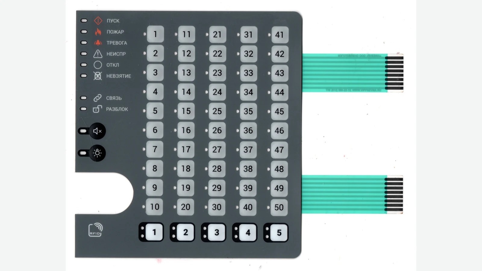
This guide sets the drawing and validation inputs for membrane-switch tail routing. Quantitative values are construction-specific screening references, not universal drawing limits or finished-product acceptance criteria.
1. What Membrane Switch Tail Bend Radius Actually Means
A bend-radius callout is useful only when the drawing defines what is being measured. In this guide, R means the inside radius of the flexible tail at the controlled bend, and t means the finished thickness of the flexible stack inside that bend zone. A statement such as “3 mm bend radius” is incomplete if the drawing omits the stack, bend angle, duty cycle, and datum.
The ratio R/t is a screening tool. It normalizes the bend against thickness, which is one reason flex-circuit suppliers publish ratios rather than one radius for every part. It is not a fatigue-life equation. Copper type, printed ink, adhesive, coverlay, temperature, conductor direction, neutral-axis position, bend angle, motion waveform, and manufacturing history still matter.
The neutral bend axis is the region of minimum strain. Material farther from that axis sees more tension on the outside of the bend or compression on the inside. An asymmetric shield, copper plane, thick adhesive, or local reinforcement can shift the axis away from the geometric center. That is why base-film thickness alone cannot determine a safe radius.
Name the route zones before reviewing the number
MEMBRANE-SWITCH BODY
tail root / laminated exit
straight transition
controlled free-bend zone → inside radius R, angle θ
housing anchor / strain-relief feature
unloaded straight run
stiffener transition
exposed contacts → selected connector → host PCB
The tail root, free-bend zone, anchor, stiffener edge, and connector entry are different mechanical regions. Moving the same radius from the free span to a stiffener edge can turn an acceptable route into a stress concentration. A crease is not a small-radius bend; it is uncontrolled plastic deformation and should be treated as a defect unless the supplier has approved a formed feature.
2. Read the Finished Stack Before Choosing a Radius
The first routing decision is construction, not geometry. A screen-printed silver trace on PET and an etched copper trace on polyimide may look similar in an enclosure, but their conductors, interfaces, thicknesses, and damage mechanisms are different. The selected PCB or FPC membrane-switch construction must therefore appear on the same drawing set as the tail route.
Typical stack logic, not a universal build
PRINTED PET TAIL ETCHED-COPPER FPC TAIL
printed dielectric / ink polyimide coverlay
silver or silver/carbon trace coverlay adhesive
treated PET circuit film etched copper conductor
optional printed dielectric polyimide dielectric
local connector reinforcement optional second copper layer
coverlay adhesive + coverlay
local connector stiffener
finished bend-zone thickness t ↑
(count every continuous layer in the bend zone)
PET films used for membrane-touch-switch graphics and circuitry are available in 125, 175, and 250 µm grades, with surface treatments for conductive inks and dielectrics. Those are film options, not finished-tail radii. Ink build, dielectric print, adhesive, trace geometry, cure history, and any reinforcement remain part-specific.
Etched-copper FPC laminates can use rolled-annealed (RA), electrodeposited (ED), or double-treated RA copper with different copper and dielectric thicknesses. Acrylic sheet adhesives can add 13–102 µm when used for layer, stiffener, or heat-sink bonding. These stack variables must be included in the bend-zone thickness; they do not define a finished-tail radius by themselves.
| Tail construction | What controls the bend review | Safe design posture | Do not assume |
|---|---|---|---|
| Printed silver or silver/carbon on PET | PET grade and thickness, ink system, printed dielectric, trace geometry, cure, fold direction, adhesive creep | Obtain the finished stack and a route-specific supplier test | Copper-FPC R/t rules or dynamic life transfer directly |
| Single-layer copper/polyimide FPC | Finished thickness, copper type and grain direction, coverlay, bend direction, plated copper in the bend | Use a named supplier rule as a screen, then validate the assembled route | Thin automatically means dynamic-rated |
| Double-layer copper/polyimide FPC | Total thickness, stacked versus staggered conductors, neutral-axis balance, vias/planes, coverlay | Increase conservatism; prefer static use unless the construction is designed and tested for motion | A one-layer radius remains valid |
| Multilayer or shielded FPC | Layer count, bonding, shield pattern, copper planes, local asymmetry, unbonded zones | Require specialist DFM and a construction-specific test plan | One generic multiplier covers every stack |
| Stiffened connector end | Connector cable-thickness window, stiffener material/length, adhesive, contact geometry | Keep the controlled bend beyond the stiffener transition and preserve a straight insertion run | The stiffener is a bend zone or a strain-relief device by itself |
The stiffener is counted in the connector-end thickness check, but it should not be folded into t for a separate free-bend region. Place the stiffener under the termination and treat its edge as a strain-relief boundary. A hard support protects the contacts while creating a sharp change in bending stiffness. The route must manage both facts.
3. How to Set a Membrane Switch Tail Bend Radius for Static and Dynamic Use
Classify the use before selecting a multiplier. “It only bends during assembly” is a testable statement about the product and process, not a label placed on the drawing. A tail that vibrates against a housing rib, moves whenever a cover opens, or is pulled during service is not truly static.
| Use profile | What it means | Radius decision | Minimum validation posture |
|---|---|---|---|
| Flex-to-install | The tail is formed during assembly and remains supported in one position | A construction-specific static supplier rule may be used as the first screen | Full installation in the production sequence, continuity before/after, visual inspection, retained radius check |
| Service bend | The route moves during planned access, replacement, or connector service | Count the maximum expected service events and include misalignment and handling variation | Repeated service simulation on finished assemblies plus connector mating limits |
| Vibration-driven flex | Nominally fixed tail experiences recurring movement from equipment vibration, shock, fan flow, or panel motion | Treat as semi-dynamic until motion at the free span and anchor is measured or bounded | In-motion continuity and assembly-level environmental testing |
| Dynamic flex | The tail bends repeatedly during normal operation, such as a hinge, carriage, or moving control head | No generic membrane-switch radius is sufficient; design the FPC, motion path, copper, stack, and fixtures as a dynamic system | Duty-cycle test at specified radius, angle, waveform, frequency, dwell, temperature, orientation, and electrical load |
Use the construction-specific ratio, not a universal multiplier
For defined copper/polyimide flex constructions, early static screens include:
- One- and two-layer RA-copper flex uses published starting points from 6t to 12t; count coverlays, bondplies, shielding films, and every other continuous layer in t.
- Double-layer flex uses a published static reference of 12t.
- Multilayer flex uses a published static reference of 24t.
- A defined one- or two-copper-layer polyimide flex-to-install construction bent no more than 90 degrees uses a published reference of 10t; more demanding motion requires separate engineering review.
These values are not interchangeable universal limits. The laminate, layer count, total thickness, bend angle, and use class determine which screen applies.
Published reference points for early DFM
Use the following values as early DFM screens only within the stated construction and use boundaries. They are not released drawing limits or finished-product acceptance criteria.
| Data field | Early DFM reference | Selection basis | Release boundary |
|---|---|---|---|
| Static printed PET/silver tail | 2.5 mm (0.10 in) minimum inside radius | Several membrane-switch design guides publish 0.100 in, while one published example uses 1.6 mm | Confirm against the finished stack, trace layout, installation sequence, and supplier DFM |
| Static one- or two-layer copper/polyimide tail, bend ≤90° | R ≥ 12t | Published flex-circuit guidance spans 6t to 12t for defined one- and two-layer constructions; 12t is the more conservative screen | The exact laminate supplier and released construction control |
| Static sample bend screen | 25 bends at 20°C | One published membrane-switch guide uses this screen; its cited ASTM F1683 method is withdrawn | Use only as an early sample screen and define the approved method, sample size, electrical threshold, and acceptance rule for release |
Apply R ≥ 12t only as an early screen when the route is static, the construction is one or two copper layers on polyimide, the bend is no greater than 90 degrees, and the bend sits in a clean free span. Use 2.5 mm only as an early screen for a static printed PET/silver tail before the exact stack review. A stricter supplier rule always controls. Multilayer, shielded, dynamically flexed, or incompletely defined tails still require construction-specific evidence.
The correct output of this stage is not merely a radius. It is a controlled statement such as: “Static flex-to-install; inside radius R; bend angle θ; finished bend-zone stack t; bend center located from datums A and B; no conductor width change, access opening, stiffener edge, or connector entry inside the bend zone; validate after the production installation sequence.”
4. Membrane Switch Tail Routing, Flex Tail Strain Relief, and Connector Access
Good membrane switch tail routing gives each region one job. The free span bends; the housing feature removes service load; the stiffener stabilizes the contact end; and the connector makes electrical contact. Asking one sharp transition to perform all four jobs creates a failure point.
Put the bend in a controlled free span
Start the controlled bend after a straight transition from the laminated tail root. End it before the housing anchor, stiffener transition, exposed contacts, or connector entry. The drawing should locate the center of the bend and its keep-out boundaries, not just show a curved leader with R MIN floating nearby.
For etched-copper flex, run conductors as close to perpendicular to the bend as possible, keep conductor width and thickness constant through the bend, stagger traces between layers, and exclude plated through-holes. A neck-down, via, coverlay opening, slit end, solid copper plane, or abrupt width change inside the bend creates a geometry change exactly where strain is already concentrated.
The bend direction matters as well. If an asymmetric stack places conductors far from the neutral axis, flipping the tail changes whether those conductors see outside tension or inside compression. “Circuit side up” is therefore not enough; the drawing should show the bend direction, connector contact side, and installed orientation.
Use strain relief to remove pull and twist, not to create a new hinge
Flex tail strain relief is the transition that keeps enclosure loads, service pulls, and vibration out of the connector and tail root. It can be a broad, smooth housing capture, a supplier-approved bonded support, or another feature that limits axial and torsional movement without pinching the conductors. The feature should:
- contact the tail over a controlled area rather than a knife edge;
- preserve the specified radius on both sides of the capture;
- avoid forcing the flexible stack against a burr, screw boss, bezel corner, or sharp slot;
- leave enough slack for tolerance, insertion, and thermal movement without creating an uncontrolled loop;
- remain outside the exposed-contact and actuator zones; and
- be evaluated in the same installed orientation used for qualification.
A stiffener is not automatically strain relief. It gives the contact end the thickness and rigidity required by a connector, but its edge is also a stiffness discontinuity. The bend should not start at that edge unless the flex and connector suppliers explicitly approve the transition.
Design membrane switch connector access from the exact part number
Do not load an inserted FPC or bend it sharply near the insertion slot. Keep the bend away from the actuator, align the stiffener with the PCB, and fix the FPC when continuous load, shock, or vibration can reach the connection.
These are connector-family instructions, not generic dimensions. The selected connector drawing must control:
| Connector input | Why it belongs in the mechanical review |
|---|---|
| Exact manufacturer and part number | “0.5 mm ZIF” does not define actuator, cable thickness, contact geometry, or insertion depth |
| Pitch and position count | Controls tail width, contact layout, and registration tolerance |
| Top/bottom contact side | Controls which face carries exposed conductors and whether the installed fold is correct |
| Horizontal/vertical insertion direction | Sets the straight approach path and assembly motion |
| Accepted FPC/FFC thickness | Determines finished contact-end stack and stiffener design |
| Exposed-contact and stiffener geometry | Controls electrical engagement, rigidity, and transition location |
| Actuator opening envelope | Reserves finger, tool, and housing clearance before the PCB is trapped |
| Mating and service limits | Keeps prototype rework or field service from exceeding connector-specific use |
| Cable load restrictions | Determines the anchor location and unsupported straight run |
Connector series define their own recommended FPC/FFC construction and thickness. Do not copy a stiffener or thickness from one ZIF family into another without checking the selected part's application specification.
Failure chain: route error to field symptom
| Route error | Local mechanical condition | Likely damage path | Electrical or assembly symptom | Useful check |
|---|---|---|---|---|
| Bend begins at the tail root | Tension and adhesive shear enter the laminated switch body | Trace cracking, printed-layer separation, or local delamination | Intermittent key matrix, open trace, lifted exit seal | Continuity while gently loading the installed route; visual inspection at the exit |
| Bend is centered on a stiffener edge | Sharp stiffness transition focuses strain | Copper/ink fracture or coverlay wrinkle/tear | Intermittent or permanent open near termination | Magnified edge inspection and in-motion resistance monitoring |
| Tail enters the connector at an angle | Connector, contacts, and exposed conductors carry route load | Incomplete insertion, conductor damage, actuator release, contact deformation | Contact failure or assembly rework | Connector lock/insertion inspection and trace-by-trace continuity |
| Tail crosses a sharp housing edge | Repeated rubbing or local compression damages insulation | Abrasion, cut dielectric, exposed conductor | Short, leakage, or later open circuit | Installed clearance check and post-environment visual inspection |
| Route has no service slack | Assembly tolerances become axial pull | Load transfers to the root or connector | Difficult insertion, unseating, intermittent contact | Worst-tolerance physical mock-up and insertion-force observation |
| Nominally static span is unsupported in vibration | Small recurring motion becomes fatigue cycling | Progressive conductor or interface damage | Vibration-dependent intermittent signal | In-motion continuity during the applicable assembly vibration test |
The table is a diagnostic map, not a promise that each route produces only one failure mode. Its purpose is to make the drawing, fixture, electrical monitoring, and post-test inspection look at the same locations.
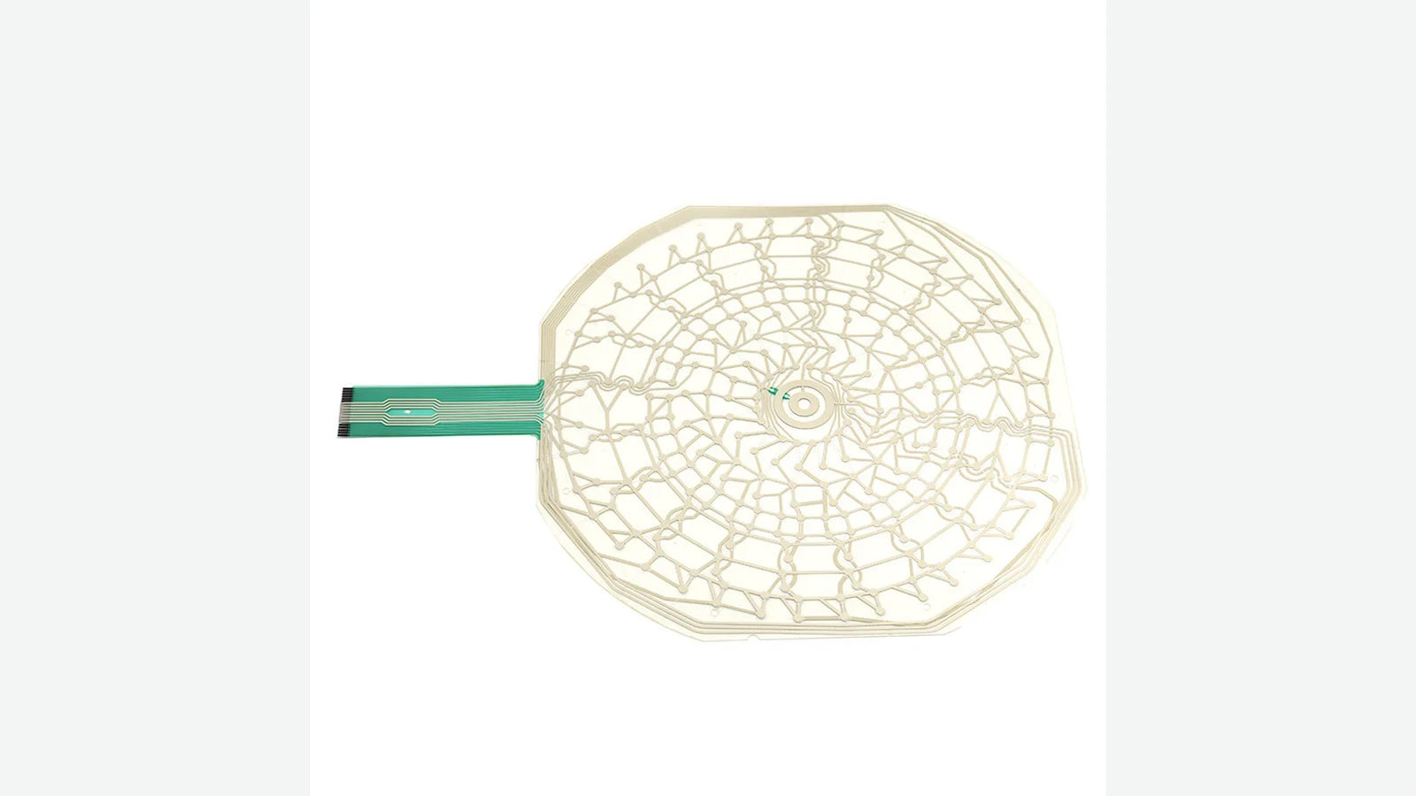
5. Turn the Route and Installation Sequence into Controlled Inputs
A tail path should be reviewed in the product assembly, not on an isolated flat sample. The enclosure, PCB position, connector actuator, operator’s hand path, tail slot, fastener sequence, and final covers determine whether the intended radius survives production.
Six-step route review
- Freeze the interface. Record the host-PCB location and orientation, exact connector part number, contact side, actuator type, and the enclosure datums that control their relationship.
- Draw the installed centerline. Show the route from tail root to exposed contacts at nominal and worst mechanical tolerance. Include slots, ribs, bosses, covers, fasteners, and any surface the tail could touch.
- Classify every movement. Separate production installation, planned service, vibration-driven motion, and operating flex. The most demanding real movement controls the design posture.
- Attach the finished stack. Identify PET/printed ink or copper/polyimide, layer count, copper type where relevant, coverlay/dielectric, adhesive, shield, finished flexible thickness, and local stiffener build.
- Place bends and restraints. Dimension the straight transition, inside radius, bend angle, bend center, keep-out zone, anchor, and unloaded connector approach. Check both bend direction and twist.
- Rehearse the production sequence. Install representative parts using the intended tools and fastening order. Confirm that the operator does not crease, pull, reverse-fold, scrape, or repeatedly reinsert the tail to close the enclosure.
For a bundled panel, display, PCB, and membrane-switch integration, the same route review belongs in the PCB/FPC HMI assembly model. Treating the switch drawing and enclosure drawing as separate releases leaves the bend at an uncontrolled interface. The package is ready for a flex circuit DFM review only after both drawings show the same route and datums.
Drawing and project-input checklist
| Category | Required input or callout |
|---|---|
| Use | Static install, service events, vibration exposure, or dynamic motion; expected movement described rather than labeled only |
| Tail construction | Printed PET/silver or etched copper FPC; supplier stack code; layer count; copper type if relevant |
| Bend-zone stack | Finished thickness t, continuous adhesives/coverlays/shields, conductor layout, and tolerance |
| Bend geometry | Inside radius R, angle θ, bend direction, center location, straight transitions, and keep-out limits |
| Tail root | Exit location, laminate boundary, seal/filler geometry, and distance to the first permitted bend |
| Strain relief | Anchor type, contact width, edge radii, datum location, and allowed tail movement |
| Housing route | Slot/cutout geometry, edge treatment, clearance to ribs/fasteners/covers, and worst-tolerance path |
| Connector | Manufacturer, exact part number, pitch, positions, contact side, insertion direction, accepted cable thickness |
| Connector end | Exposed-contact length/finish, stiffener material/thickness/length, insertion datum, actuator clearance |
| Assembly | Tail threading, connector insertion, actuator closing, PCB fastening, cover closing, inspection points, and service removal order |
| Electrical | Pinout, traces monitored during testing, baseline resistance method, and project-defined discontinuity threshold |
| Validation | Samples, radii, angles, cycles/events, environment, orientation, monitoring, inspections, and acceptance criteria |
The route review is ready for supplier DFM only when an engineer can answer a practical question: What does the tail touch, bend around, and experience at each step from unpacking through final service? A flat DXF of the switch outline cannot answer it. Share the cable route and installation sequence with the switch and HMI supplier before tooling.
6. Validate the Finished Tail Route, Not Just a Flat Coupon
Validation should reproduce the assembled constraint system. A material coupon can compare films or conductors, but it does not include the membrane-switch exit, actual adhesive stack, housing edge, stiffener transition, connector, anchor, tolerances, or installation handling.
Route-validation matrix
| Test block | Specimen state | Variables the project must define | Monitor / inspect | Pass criteria owner |
|---|---|---|---|---|
| Drawing and dimensional review | As-built tail and connector-end stack | t, R, θ, bend-center datums, connector thickness window, tolerance stack | Measurement report and installed-radius template/fixture | OEM + tail supplier + connector drawing |
| Production installation trial | Finished switch, housing, PCB, connector, fasteners, covers | Operator sequence, tools, allowed rework, threading and fastening order | Live continuity where practical; crease, scrape, pull, and lock inspection | OEM manufacturing engineering |
| Static dwell | Fully installed assembly at worst route | Dwell, temperature, orientation, mechanical tolerance, electrical load | Before/after resistance and visual inspection | Project specification |
| Service simulation | Finished assembly opened and reclosed | Number of service events, connector operations, route handling, replacement sequence | Continuity during motion; actuator/stiffener/tail inspection | Product service requirement |
| Dynamic flex | Representative production stack and fixtures | Radius, angle, stroke/waveform, frequency, cycles, dwell, temperature, orientation, load | Continuous or sampled resistance with defined discontinuity threshold; post-test microscopy | OEM reliability plan |
| Temperature / humidity sequence | Installed assembly | Application extremes, rates, dwell, powered/unpowered state, recovery | Electrical drift, delamination, adhesive movement, visible cracking | Product environmental requirement |
| Vibration / shock | Installed assembly with production restraints | Applicable axes, spectrum/levels, duration, mounting, powered state | In-motion continuity; connector lock, abrasion, anchor, root and stiffener-edge inspection | Product environmental requirement |
| Post-test teardown | Tested finished assemblies | Inspection magnification, destructive cross-section locations, trace selection | Coverlay/dielectric damage, conductor cracks, interface separation, contact wear | Agreed approval plan |
Use IEC TR 62899-550-1:2022 as the framework for mechanical and thermal durability of printed and flexible electronics, including bending, torsion, stretching, steady heat, and thermal cycling. Use IEC 60068-2-6:2007 for sinusoidal-vibration testing when the equipment environment requires it. Neither standard supplies the product's radius, sample size, cycle count, electrical load, or pass limit; the OEM must define those conditions from actual service.
The quality and testing plan should also record the design standard and revision used. IPC-2223 is the sectional design-standard family for flexible and rigid-flexible printed boards. Revision-status pages can differ. Confirm the contract revision at drawing release rather than copying it from an old template.
25 bends at 20°C appears in one published vendor guide and may be used only as an early static-handling screen. It is not dynamic qualification, a JASPER acceptance method, or a current ASTM requirement.
Two membrane-switch methods often seen in older guides are withdrawn: ASTM F2750-16 was withdrawn in 2023 and ASTM F1683-09 was withdrawn in 2018 with no replacement. They can inform a mutually agreed historical procedure, but neither is a current ASTM acceptance standard. If an old customer drawing invokes one, resolve the contract requirement explicitly before testing.
Sample-approval closeout
Approve the route only after the as-built stack matches the drawing, the minimum installed radius survives worst tolerance, the tail clears every sharp or moving feature, the connector is fully seated and locked, all specified traces pass the electrical criteria, and post-test inspection finds no prohibited crease, crack, abrasion, wrinkle, or delamination. Record exceptions; do not convert a bench-working sample into an unwritten production waiver.
7. When an Integrated Membrane-Switch Tail Is Not the Best Choice
The recommended static, stack-aware route is not the right construction for every enclosure. In an industrial equipment HMI, vibration, panel motion, and service access can turn a nominally static tail into a recurring flex point. Change the architecture when the available path cannot provide the supplier-approved radius, unloaded connector entry, strain relief, and validation margin.
| Scenario | Why the integrated tail is a poor default | Better design direction |
|---|---|---|
| Repeated hinge, carriage, or rolling motion | A standard printed PET tail or ordinary multilayer FPC is not automatically designed for dynamic fatigue | Use a dynamically engineered and tested copper FPC or a separately qualified moving cable system |
| Connector is hidden after final assembly | Operators may need blind insertion, repeated rework, or a forced tail angle | Reorient or relocate the connector, use an intermediate interconnect, or change the assembly split |
| Tail must twist while bending tightly | Combined torsion and bending invalidate a simple planar R/t screen | Add path length and controlled 3D support, or separate the motion from the membrane-switch tail |
| Service loads can pull the cable | The tail root and miniature connector become structural load paths | Add a serviceable harness or housing-level retention that bypasses the switch tail and connector |
| Shielded or multilayer stack must fit a very small radius | Added thickness, copper, and asymmetry raise strain and stiffness | Move the PCB/connector, enlarge the bend envelope, or redesign the stack with the flex specialist |
Changing from printed PET to copper FPC is not a universal cure. The copper construction still needs the correct layer count, copper type, bend zone, connector, motion definition, and test. If the enclosure cannot support those inputs, the mechanical architecture—not the radius callout—needs revision.
8. Frequently Asked Questions
What is the minimum membrane switch tail bend radius?
There is no universal minimum. Published guides use screening points such as R ≥ 12t for defined static one- or two-layer copper/polyimide tails and 2.5 mm for some static printed PET/silver tails. The exact laminate supplier, finished stack, trace layout, installation route, and validation plan control the released design.
How is flex tail bend radius calculated from thickness?
Multiply the supplier-approved bend ratio by the finished flexible thickness in the bend zone: R = ratio × t. Use the drawing-defined inside radius and count continuous copper or ink, dielectric, coverlay, adhesive, and shield layers. Do not use only the base-film thickness or include a separate connector stiffener as ordinary free-bend material.
Can printed PET/silver and copper/polyimide FPC use the same bend rule?
No. Printed PET/silver and etched copper/polyimide FPC use different substrates, conductors, interfaces, and manufacturing processes. A copper-FPC multiplier cannot establish PET-tail reliability. Specify the actual finished stack, trace system, bend direction, environment, and duty cycle, then obtain construction-specific supplier guidance and test the assembled route.
What is the difference between static and dynamic tail bending?
Static, or flex-to-install, means the tail is formed during assembly and remains supported. Dynamic flex repeats during normal operation. Service access and vibration sit between those cases and can create recurring motion. If the route moves after assembly, quantify that motion instead of labeling the tail static by intent.
How far should a bend be from the tail exit, stiffener, or connector?
No generic distance covers every stack and connector. Keep the controlled bend in a free span, beyond a straight transition from the laminated tail root and before the stiffener or connector entry. Dimension those boundaries. The tail supplier and exact connector application specification should approve the final straight-run distances and route.
What does flex tail strain relief do?
Flex tail strain relief keeps pull, twist, vibration, and service handling out of the tail root and connector. It should capture the tail over a smooth, controlled area without creating a crease or hard hinge. A connector stiffener stabilizes the contact end but does not automatically provide system-level strain relief.
What membrane switch connector access details belong on the drawing?
Show the connector manufacturer and exact part number, pitch, position count, contact side, insertion direction, accepted cable thickness, exposed-contact geometry, stiffener build, insertion datum, actuator swing, hand or tool clearance, and service path. Also show the unloaded straight approach and the housing anchor that prevents tail load at the connector.
How should an OEM validate membrane switch tail routing?
Test the finished switch, housing, PCB, connector, restraints, and production installation sequence. Define radius, angle, movement, events or cycles, temperature, vibration where applicable, electrical load, continuity threshold, sample size, and inspections. Monitor the relevant traces during motion and inspect the tail root, bend, anchor, stiffener edge, and contacts afterward.
9. What to Do Next
Freeze the route before tooling: select the connector, define the finished tail stack, classify every movement, dimension the bend and keep-out zones, place strain relief, and rehearse the installation sequence. If tail exit direction is still open, resolve it before this review; it changes both the available radius and connector approach.
Send the enclosure section, PCB layout, exact connector datasheet, tail pinout, installed route, bend angle, motion profile, and step-by-step assembly sequence with the switch drawing. JASPER can be listed as one manufacturer option for reviewing that package and preparing a construction-specific DFM response. The same evidence should be requested from any qualified alternative. Share the cable route and installation sequence rather than asking for an isolated “minimum bend radius.”
Technical Sources
Technical values are tied to the named document, product grade, and stated test boundary.
Technical references
- Source: All Flex Solutions, Minimum Bend Radius Considerations in Flexible Circuits, 2024.
- Source: Minco, Flex Circuits Design Guide, 2019.
- Source: Minco, Designing a Flex Circuit for Flexibility, 2024.
- Source: Würth Elektronik, PURE.flex Design Rules, accessed 2026.
- Source: Mylar Specialty Films, Melinex ST506 Technical Data Sheet, 2025.
- Source: DuPont, Pyralux AP Data Sheet, accessed 2026.
- Source: DuPont, Pyralux LF Acrylic Sheet Adhesive Data Sheet, accessed 2026.
- Source: Hirose, FH55/FH55M connector catalog, accessed 2026.
- Source: Molex, Easy-On FPC/FFC application specification 2297470000-AS, accessed 2026.
- Source: Hirose, FH12 connector catalog, accessed 2026.
- Source: IPC-2223, Sectional Design Standard for Flexible and Rigid-Flexible Printed Boards, accessed 2026.
- Source: IEC TR 62899-550-1:2022, mechanical and thermal durability framework.
- Source: IEC 60068-2-6:2007, sinusoidal-vibration test standard.
- Source: ASTM electronics standards status catalog for F2750-16 and F1683-09, accessed 2026.
- Source: Epec, What Is the Smallest Bend Radius of a Membrane Switch Tail?, 2014.
- Source: General Label, NFI, and Design Mark membrane-switch design guides, accessed 2026.
Freeze the installed tail route before samples
Send the finished stack, tail outline, connector, housing section, bend zones, installation sequence, service events, and validation target. JASPER Engineering will flag unsupported transitions before tooling.