
Silicone keypad actuation force should be approved as one point on a complete, conditioned press-and-release curve—not copied from a generic application table. Engineers preparing geometry, drawings, or sample approval should define peak force, make force, contact travel, overtravel, return behavior, probe, rate, support, and the installed stack. The web supplies the spring, but no reviewed public standard gives a universal “rubber keypad web ratio” equation. Begin with target users and operating conditions, then tune molded samples in the production-intent assembly. A silicone rubber keypad is not the best choice when a rigid switch, metal dome, or nonmoving capacitive surface better fits the required motion, feedback, cleaning, or safety architecture.
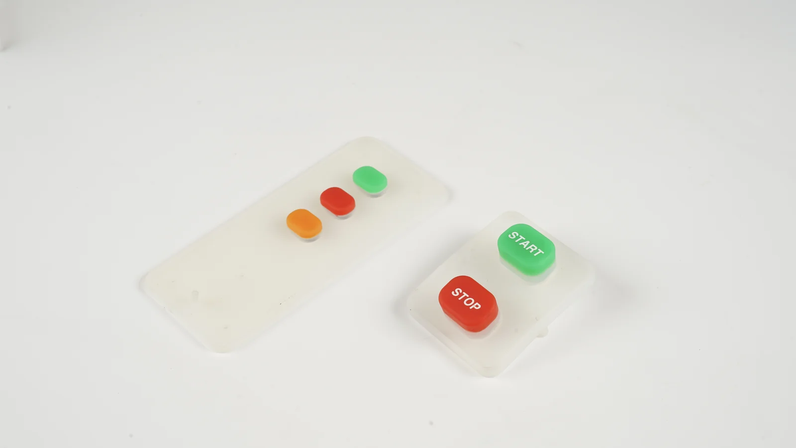
JASPER certifications: ISO 9001, ISO 13485, IATF 16949, and ISO 14001.
1. Read the Entire Keypad Force Curve, Not One Peak
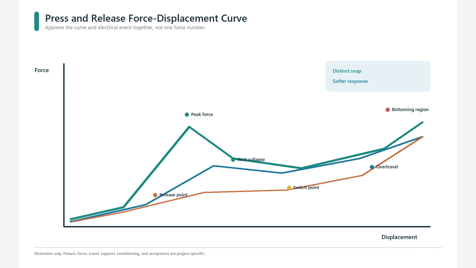
A keypad force curve plots force against key displacement during loading and release. Peak force matters, but it does not reveal when the electrical contact closes, how much useful motion remains, where the assembly bottoms, or whether the key returns with margin. Those events must be named before two curves can be compared.
Shin-Etsu Polymer Europe uses F1 for peak or actuation force, F2 for make or contact force, F3 for the force at the application's mechanical end stop, S1 for peak travel, and S2 for contact travel. Its click-ratio equation is (F1 − F2) / F1 × 100%. Other supplier documents assign the same symbols differently—some use F3 for return force—so an OEM drawing should pair every symbol with a plain-language definition.
Force
^
end-stop / bottom-out region
/
F1 peak /
/\ /
/ \ → F2 make → /
/ · press path
/ · electrical closure at S2
→ / → · → > Travel
rest S1 S2 overtravel
\ →
release path \ → returned state
The diagram is a naming aid, not a standard test trace. A real key may show a rounded peak, several contact transitions, a secondary rise from a guide, or no snap at all. The test report should preserve the observed shape instead of forcing every key into a crisp-dome model.
| Curve item | Working definition | Design question it answers | Common specification error |
|---|---|---|---|
| Rest / preload | Force and travel reference before the commanded press | Is the installed key already compressed by the bezel, gasket, fasteners, or PCB stack? | Taring away an unknown assembly preload |
| F1: peak / actuation force | Highest intended web-collapse force inside a defined search interval | How much force starts the tactile transition? | Reporting a later housing stop as F1 |
| F2: make / contact force | Force at the defined electrical make event | Is stable closure reached after the intended tactile event? | Calling F2 “contact resistance,” which mixes force and resistance units |
| ΔF | Absolute force drop, F1 − F2 | How large is the mechanical drop after the peak? | Keeping only the percentage ratio |
| Click ratio | ΔF / F1 × 100% | How large is the press-path drop relative to F1? | Treating the ratio as return force or life evidence |
| S1 / S2 | Travel at F1 / travel at the defined make event | Does the tactile event occur before stable electrical closure? | Using “travel” without naming the endpoint |
| Overtravel | Displacement after the make event and before the controlled end point | Can tolerance stack and finger motion be absorbed without damaging the contact or structure? | Measuring from an undefined zero or to a fixture limit |
| End-stop / bottom-out force | Force caused by the production-intent stop or maximum approved travel | Which physical feature limits motion? | Letting the tester, not the product, define the stop |
| Release-open event | Force and travel where the electrical state opens on return | Does the contact release at a controlled point? | Recording the press path only |
| Minimum return force | Lowest approved restoring margin at a named return location | Can the web overcome guide friction, preload, and assembly drag? | Inferring return from click ratio |
The loading and unloading paths form a hysteresis loop. Research on automotive keypads treats force and stroke as paired quantities, while a 2017 Applied Ergonomics study found that F1/F2, stroke, absolute drop, and snap ratio related to different perceived qualities. That is the practical reason to specify the complete curve.
Use newtons as the primary force unit. If a supplier also reports gram-force, write gf, not g: NIST gives 1 kgf = 9.80665 N, so 100 gf = 0.980665 N. A drawing that says “150 g actuation” is dimensionally ambiguous.
2. How Silicone Keypad Actuation Force Relates to Travel and Return
Silicone keypad actuation force, silicone keypad travel, and return behavior are coupled but not interchangeable. F1 describes the press peak. S2 locates the selected electrical make event. The return path shows whether the key opens and recovers. A design can hit one target and still fail the other two.
Follow the event sequence
- Approach and preload: the probe or keycap reaches the rest surface. Hidden bezel or gasket compression may already load the web.
- Rising stiffness: the angled web bends and stretches as force rises toward F1.
- Transition: the web changes shape after the peak. Force may drop sharply, gradually, or barely at all.
- Electrical make: a conductive pill, plunger, or separate switch reaches the project-defined closure threshold at S2.
- Overtravel and stop: the remaining stack accepts motion until the intended product stop—not the tester limit—controls displacement.
- Release and opening: force follows a different path while the electrical contact opens.
- Recovery: the key returns to its defined rest position with enough margin to overcome guide friction, residual preload, and part variation.
Click ratio describes step 3 on the press path. It says nothing by itself about step 6 or 7. Vieira and colleagues tested eleven in-vehicle rubber keys and found that absolute force drop ΔF was a better predictor of perceived clickiness than snap ratio in that dataset; snap ratio instead related to pleasantness. The result does not create a universal preference. It does show why “50% snap” cannot stand in for the whole key feel.
Consider two keys with the same 50% ratio. A key with F1 = 1.0 N and F2 = 0.5 N drops 0.5 N. A second key with F1 = 2.0 N and F2 = 1.0 N drops 1.0 N. Their ratios match, but their absolute forces do not. They may also close at different travels, bottom against different stops, and return through different hysteresis loops.
Use curve signatures as test hypotheses
The following failure chains are diagnostic hypotheses. Each chain must be separated by measurement; none is a universal one-cause rule.
| Observed signature | Possible chain | First separating checks |
|---|---|---|
| F1 is high but S2 is unchanged | Web section, compound state, or press alignment shifts stiffness while contact height stays similar | Compare section data, material lot, center alignment, and loose-part curves |
| S2 moves but F1 stays similar | PCB support, contact height, pill height, or assembly gap changes the make event after the web transition | Synchronize electrical state; measure the installed stack and PCB deflection |
| Late, steep force rise | Keycap, guide, bezel, housing rib, fixture, or compressed stack becomes the stop | Inspect witness marks; repeat with the production-intent cap and a verified travel limit |
| Center press passes; edge press binds | Long-key mechanical advantage, guide clearance, asymmetric web loading, or local support introduces tilt and friction | Overlay center, corner, and edge traces; inspect motion from the side |
| Press path repeats; release path drifts | Mechanical history, residual compression, friction, contamination, or recovery time affects return | Plot cycle order, rest time, release speed, and loose-versus-installed curves |
| Contact chatters after make | Contact surface, PCB pattern, bounce threshold, local tilt, or insufficient post-make control is unstable | Capture the electrical channel at the same time base as force and travel |
Return force needs its own event definition. “Minimum return force” could mean the lowest force on the unloading curve between electrical opening and a named near-rest position, or another project-defined point. The drawing must say which. A single value measured at an unknown travel cannot show whether the key opens cleanly, pauses against a guide, or returns to the original baseline.
Silicone also has time-dependent behavior. Under constant compression, rubber counterforce can decay; ASTM D6147 and ISO 3384-1 address stress relaxation at the material-test level. Those standards do not predict a keypad's installed return force. They establish a boundary: a one-time press curve cannot replace conditioned return, repeated-cycle, and post-exposure checks.
3. Is “Rubber Keypad Web Ratio” a Standard Specification?
No universal rubber keypad web ratio was found in the public standards, research papers, or primary keypad sources reviewed for this guide. Public design guides discuss web thickness, height or free length, angle, radii, and force-based click ratio. They do not converge on one geometry equation called web ratio.
If a drawing uses the term, define it as a project characteristic. At minimum, state:
- the numerator and denominator, with units before division;
- the exact section, or the rule for several sections around a noncircular key;
- the free, installed, or loaded measurement state;
- the datum and measurement direction;
- whether dimensions are nominal CAD values or measured-part values;
- how initial, taper, blend radii, flash, and parting features are treated; and
- the instrument, contact pressure, and reporting resolution for molded-part measurements.
Do not equate a geometry ratio with click ratio. Click ratio is calculated from two forces. A web ratio, if a project defines one, is calculated from named dimensions. Matching either ratio does not prove that peak location, contact travel, edge behavior, or return margin also match.
Treat the web as a three-dimensional spring field
The sloping web is not an isolated line on a section view. It transfers load from the keytop to the keypad base while interacting with the stem, contact, PCB, support, guide, and enclosure stop.
finger or test probe
rigid/soft keytop · guide or bezel contact
stem and inner fillet → sloping web around the full perimeter
outer fillet and keypad base → local PCB / housing support
conductive pill or actuator → circuit contact → product end stop
Rubber-diaphragm loading and unloading are strongly nonlinear because geometry and material act together. Hirashima and Zako modeled that behavior with nonlinear finite-element analysis; a NAFEMS keypad study likewise concluded that material data alone do not predict the product curve and combined physical tests with a hyperelastic model. Simulation can reduce trial loops, but a model still needs material characterization, boundary conditions, and correlation to molded parts.
| Variable family | First curve features to watch | Coupled inputs that can reverse or mask the result | Drawing / test control |
|---|---|---|---|
| Web thickness around the perimeter | Initial slope, F1, ΔF, release path | Free length, angle, radii, compound, cure, local flash | Dimension a section field; identify measurement locations and method |
| Web height / free length | S1, S2, available travel, buckling sequence | Keytop height, contact gap, stop height, preload | Control free height and installed stack separately |
| Web angle | Collapse mode, peak location, lateral motion | Thickness, inner/outer diameter, asymmetric footprint | Section the actual key; do not copy an angle from a different diameter |
| Inner and outer fillets | Stress concentration, stiffness transition, repeatability | initial, tool polish, gate/parting location, local section change | Dimension functional radii where measurable; correlate to curves |
| Keytop and stem stiffness | Load distribution, off-axis tilt, apparent F1 | Cap material, cap bond, guide, press point | Test production-intent cap and defined center/edge points |
| Contact height and PCB gap | S2, overtravel, end-stop timing | Pill compression, PCB flex, support ribs, adhesive stack | Synchronize electrical make; dimension the full contact stack |
| Perimeter compression | Rest preload, baseline, hysteresis, return | Fastener sequence, gasket, housing flatness | Preserve installed preload; do not hide it with an undocumented tare |
| Compound and process state | Overall stiffness, damping, recovery | Geometry, cure/post-cure, lot, age, prior cycles, temperature | Control grade, lot, process status, conditioning, and test age |
Shore A is not a shortcut to finished-key force
ASTM D2240 defines durometer hardness through indentation. The result has no simple relationship to a fundamental material property. It is a useful material-control characteristic, but it does not include the keypad's web, cap, contact gap, PCB, housing, or stop.
A concrete example makes the boundary clear. Dow lists SILASTIC DY 32-765 U as a 50-durometer silicone rubber for molding and keypad applications, yet its datasheet explicitly tells specification writers not to use the listed typical properties as specifications. A named grade and hardness still do not deliver a finished F1, S2, click ratio, or return-force target.
Dimensional conformance and functional conformance are separate
ISO 3302-1 defines dimensional-tolerance classes for molded solid-rubber products; ISO 3302-2 covers geometrical items such as flatness, parallelism, perpendicularity, coaxiality, and position. Those frameworks can organize a drawing, but a key can meet its dimensions and miss its curve because several dimensions, material state, and assembly conditions interact.
The measurement method matters at thin flexible sections. ASTM D3767 addresses measurement of rubber-product dimensions, where contact method and pressure can affect the observation. Record the section location, instrument, contact geometry, and part state. Then pair the dimensional record with the force curve from the same identified sample whenever a geometry-to-feel decision is being made.
4. Measure Silicone Keypad Travel and Force With a Locked Method
A reproducible silicone-keypad test fixes the specimen state, load path, motion, environment, channels, and event rules before it sets an acceptance band. Otherwise, the report mixes part variation with fixture flex, alignment, rate, filtering, contact logic, and assembly preload.
Instron's keypad application uses a low-capacity load cell, controlled probe, supported specimen, force/displacement capture, and—when needed—an electrical channel to locate switch closure. Canadas and colleagues reached the same basic architecture in an automated car-radio keypad system, noting that the small forces and strokes demand high precision and repeatability. Neither source supplies a universal keypad speed or probe.
The project testing and validation plan should control these fields:
| Method field | Minimum controlled record | Why the result can move |
|---|---|---|
| Specimen identity | Part and drawing revision, material lot, molding date/age, cavity or source identity when available, key position, prior test history | Mixed revisions or histories can look like random process variation |
| Test state | Loose keymat, PCB-supported keypad, keypad assembly, or complete enclosure | Support, preload, guides, stops, adhesive, gaskets, and fasteners change the load path |
| Support and assembly | Fixture drawing, PCB support map, clamp/fastener condition, assembly sequence | Board and housing flex add apparent travel and can shift S2 |
| Indenter | Face shape, size, material, orientation, alignment, and first-contact point | Contact pressure and tilt change how the web is loaded |
| Press locations | Center coordinates plus defined edge/corner points for large or guided keys | A user's off-axis press may expose rocking or bezel friction |
| Zero and preload | Force zero, travel zero, seating rule, installed preload | An undocumented tare can erase a real assembly condition |
| Motion profile | Approach, loading speed, maximum travel or force, dwell, unloading speed, recovery time | Silicone and the measurement system respond to time history |
| Synchronized channels | Force, local or machine displacement, elapsed time, electrical state; optional video | Unsynchronized contact data can place make/open on the wrong curve segment |
| Electrical event | Circuit, excitation, threshold, debounce rule, first versus stable closure | “Contact” can mean a transient, a resistance threshold, or controller logic |
| Acquisition and processing | Sample rate, filter, smoothing, interpolation, event algorithm, software revision | Filtering can move or erase a narrow peak or bounce event |
| Environment | Test and conditioning temperature/humidity; project exposures | Elastomer response and fixture dimensions can change with condition |
| Cycle state | Seating cycles, recorded cycle numbers, dwell and recovery between groups | Mechanical history can change hysteresis and peak force |
| Calibration and uncertainty | Force-system pairing, calibrated range, displacement verification, resolution, uncertainty, zero checks | A calibrated sensor name alone does not establish system performance |
| Sampling and traceability | Parts, lots, cavities, key roles, repeated setups, operator/fixture rebuilds | Averages can hide position, lot, or setup effects |
Rate, temperature, and cycle history are method variables
Test speed is not clerical detail. Nagurka and Marklin measured three rubber-dome keyboard keys and found peak force at 80 mm/s more than 12% above the 0.5 mm/s result. That difference belongs to their keys and apparatus; it is not a correction factor. It proves that a handheld peak reading and a controlled force-displacement trace are not automatically comparable.
Temperature belongs in the record for the same reason. A 2023 silicone-rubber study measured temperature- and frequency-dependent dynamic viscoelastic behavior under its material-test conditions. The study cannot predict an assembled keypad, but it supports testing at controlled laboratory conditions and at project-relevant extremes when the decision requires them.
Mechanical history matters too. Persson and Andreassen documented hysteresis, recovery, stress relaxation, compression set, and the Mullins effect during cyclic compression of several elastomers, including one liquid silicone rubber. Their cycle counts and strains are research conditions, not keypad recommendations. A keypad method should simply declare the seating cycles, recorded cycle numbers, dwell, and recovery time rather than leaving them implicit.
ISO 23529 addresses preparation, storage, conditioning, and time between forming and testing for rubber test pieces; its scope does not supply special whole-product requirements. ASTM D1349 provides standard-condition choices for rubber testing while allowing the specific project method to take precedence. Use those documents to control comparability, then add the complete keypad and assembly method.
Calibrate the measurement system that produces the decision
ASTM E4-24 covers calibration and verification of static or quasi-static testing-machine force systems with SI traceability and stated uncertainty. When a force transducer is calibrated with a readout, the result applies to that transducer/readout pairing. A calibration sticker on one component does not document the full force channel.
The uncertainty review should include load-cell range and resolution, zero drift, probe alignment, machine and fixture compliance, displacement reference, contact threshold, channel timing, repositioning, environment, and event extraction. JCGM 100 supplies the general framework for identifying and combining uncertainty contributions; ISO 5725-1 supplies the language for trueness and precision studies. Neither document chooses an acceptance tolerance or sample count.
Before comparing material lots, prove repeatability at several levels:
- repeated cycles without moving the part;
- repeated zero and approach sequences;
- remove-and-reinstall trials;
- fixture rebuild or support reset;
- a second operator setup when the operator affects alignment; and
- cross-system checks when two laboratories must agree.
Keep each raw press/release trace tied to the specimen, key position, assembly build, environment, and cycle order. A mean curve without those identities is difficult to diagnose.
Use standards for their actual scope
| Document | Useful role in a keypad plan | Does not establish |
|---|---|---|
| ISO 9241-410:2008 | Select physical-input characteristics for intended users, tasks, software, and environment | One best force or travel for every user |
| IEC 61020-1:2019 | General electromechanical-switch framework that includes returning force and actuator travel | Automatic applicability or compliance for every silicone keypad |
| ASTM D2240-15(2021) | Durometer hardness control | Finished-key force or feel |
| ASTM D575-91(2024) | Rubber-compound compression-deflection comparison | A molded keypad force-curve method |
| ASTM D395-18(2025) / ASTM D6147-97(2026) | Compression set / stress relaxation under their material-test conditions | Dynamic key life or installed return-force acceptance |
| ISO 23529:2016 / ASTM D1349-14(2024) | Conditioning and environment controls | A complete finished-key test |
| ISO 3302-1:2014 / ISO 3302-2:2022 | Dimensional and geometrical tolerance frameworks | Functional curve conformance |
| ISO 5893:2019 / ASTM E4-24 | Constant-rate machine and force-system controls | A keypad-specific speed, probe, fixture, or event rule |
| ASTM F1578-24 | Repeated membrane-switch actuation and optional electrical loading when the assembly falls within the agreed scope | A universal cycle count for silicone keypads |
| ASTM F2592-16 | Historical force-displacement vocabulary | Current compliance; ASTM withdrew it in November 2023 without replacement |
5. Choose the Construction by Use Case—and State When Silicone Is Not Best
The right construction follows the operator, task, environment, circuit, and risk—not an application label such as “industrial” or “medical.” ISO 9241-410 frames physical-input design around the intended context of use rather than one inherently usable device category. The same principle applies to the force curve.
| Operating scenario | Useful design direction | Validation that matters | When a molded tactile web may not be best |
|---|---|---|---|
| Repeated numeric or menu entry | Lower-effort, consistent keys; short decision time; stable center and edge response | User trials, repeated-entry fatigue, full curve, bounce, recovery, position-to-position spread | A discrete mechanical switch may suit a narrowly controlled signature or field replacement requirement better |
| Gloved industrial control interface | Deliberate travel and clear feedback; cap and guide sized for off-axis use | Actual gloves, cold/hot conditions, contamination, edge presses, installed return | A guarded mechanical control may be better where accidental activation consequences dominate |
| Outdoor or marine panel | Sealed keymat, drain/vent strategy, guides that tolerate contamination, stable installed stop | Temperature, water/cleaner exposure, salt or UV plan as applicable, post-exposure return | A nonmoving capacitive surface may simplify cleaning, but only if water, glove, and false-touch behavior are validated |
| Medical equipment HMI | Cleanable interface, low ambiguity, defined electrical event, controlled material and process records | Intended cleaner, glove, use-error evaluation, assembly curve, post-exposure function | A flat membrane switch or capacitive panel may be preferable when crevice control or minimal movement outweighs molded key travel |
| Automotive or mobile-equipment HMI | Production-intent cap, guide, bezel, PCB, and temperature-conditioned curve | Center/edge presses, rate and temperature matrix, rattle/rub checks, installed build traceability | A metal dome or separate switch can be stronger when a crisp discrete transition and constrained package drive the architecture |
| Long rocker, cursor, or oversized key | Stabilized cap, symmetric support, directional web analysis, multiple press locations | Corners, both ends, diagonal presses, tilt, guide friction, contact sequencing | A pivoted rocker or multiple discrete switches may control motion more predictably than one broad elastomer web |
| Silent or flush interface | Low-click molded response or no-moving-part sensing | False touches, debounce, cleaning, gloves, visual/audio confirmation | Capacitive sensing is often the cleaner architecture when physical travel is unwanted; it needs another feedback mechanism if touch confirmation is required |
A molded silicone web is also the wrong default for a dedicated emergency stop, guard-interlock reset, or other function that requires a separately specified safety architecture. A tactile keypad key may send a command, but its pleasant click does not establish system-level risk reduction, redundancy, diagnostic coverage, or regulatory acceptance.
The opposite mistake is choosing a rigid switch solely because its laboratory curve is crisp. A molded keymat can combine many keys, flexible sealing features, legends, light paths, and a compliant interface in one part. The choice depends on the complete HMI stack and its validation burden.
The silicone keypad control-interface case is a related manufacturing reference, not evidence for a universal force value or a specific customer result. Use it to understand construction context. Use production-intent samples to approve feel.
6. Put the Force Curve on the Drawing and in Sample Approval
A usable release package connects the target feel to named curve events, controlled geometry, a reproducible test, and approved samples. “Soft,” “positive,” or “like the old unit” can start a discussion. None is an acceptance criterion.
user + task + environment
target F1, F2, ΔF, S1/S2, overtravel, return and stop behavior
web / cap / contact / PCB / housing stack concept
prototype geometry and tactile sample set
loose-keymat curve → installed-assembly curve → edge/corner curves
rate + environment + cycle-history checks required by the project
approved sample IDs + controlled data set + drawing limits + change control
The prototyping and sample-approval route can organize fit, feel, and assembly decisions. A separate silicone keypad assembly route helps distinguish the loose keymat from the keypad-plus-circuit stack. Neither link proves a particular instrument, fixture, tolerance, or test result; those belong in the project record.
Drawing and test-specification checklist
| Control block | Required inputs | Acceptance output | Release mistake to avoid |
|---|---|---|---|
| Use context | User population, gloves, press frequency, accidental-activation risk, task, feedback channels | Approved tactile brief and user-evaluation plan | Selecting a force from an application-name table |
| Key geometry | Key map, top/stem, full web sections, height, angle, radii, initial, key spacing, skirt/base, cap and guide | Controlled 2D drawing and 3D model with measurable characteristics | One undefined “web ratio” dimension |
| Mechanical stack | PCB/FPC, contact, support, adhesives, gasket, bezel, guide, fasteners, end stop | Installed-stack section and assembly sequence | Approving a loose keymat while production uses preload and a flexible PCB |
| Curve targets | F1, F2, ΔF, click ratio if used, S1, S2, overtravel, end-stop boundary, release-open event, minimum return rule | Target push/release envelope with units and event definitions | Peak-only requirement |
| Measurement method | Test state, fixture, probe, points, zero/preload, speed, dwell, release, channels, environment, processing | Controlled method revision and report template | Letting each supplier or lab choose a different setup |
| Variation | Material grade/lot, cavity/source, age, cycle state, sample structure, key roles | Traceability plan and defined comparison groups | Averaging unlike keys, lots, or assemblies |
| Approval | Prototype stages, raw curves, visual/dimensional data, electrical results, environment checks, master samples | Signed sample and data package tied to revisions | Approving feel without preserving the curve and specimen identity |
| Change control | Tool correction, compound/process change, cap/guide/PCB/housing revision, test-software change | Revalidation trigger and comparison plan | Assuming dimensional approval covers the functional curve |
Engineering benchmark for tactile sample discussion
Initial tactile sample benchmark: Use F1 = 1.5 N (about 153 gf), S2 = 1.0 mm, and click ratio = 50% for the first comparison. Confirm the released targets from user evaluation and production-intent samples.
The three values form a coherent calculation example: at 50% click ratio and F1 = 1.5 N, F2 would be 0.75 N. That arithmetic does not define return force, tolerance, life, web thickness, web angle, test speed, or sample count. Confirm the benchmark after the target users evaluate tactile samples and the production-intent cap, guide, contact, PCB, support, and stop are available.
Sample-approval checklist
- Preserve raw loading and unloading data, not only extracted F1 and S2.
- Identify every sample by revision, material lot, molding date or age, cavity/source when available, and key position.
- Record loose, PCB-supported, and fully installed states when each state controls a different decision.
- Test center and defined edge/corner locations for keys that can be pressed off-axis.
- Keep force, travel, time, and electrical state synchronized.
- Record zero, preload, probe, support, speed, dwell, release, environment, conditioning, prior cycles, filtering, and software revision.
- Compare individual traces and distributions; do not hide an abnormal mode inside one average.
- Recheck return and electrical opening after project-required environment or cycling exposure.
- Name the approved master sample IDs and the exact drawing, circuit, cap, housing, and method revisions.
- Define which design, material, process, tooling, assembly, or software changes trigger reapproval.
The planned silicone keypad tooling and prototyping article can own mold correction and sample-stage detail, while the planned silicone rubber keypad design guide can own the broader architecture. Those links remain intentional even if the planned routes are not yet live. This article keeps ownership of force, travel, web terminology, and curve validation.
7. Frequently Asked Questions
What is a typical silicone keypad actuation force?
There is no universal typical force for every keypad. As a initial tactile-sample brief, 1.5 N is a defensible mid-to-upper industry benchmark derived from established manufacturer guides, but it is not JASPER production data, a normative standard, or an acceptance limit. User, task, key size, geometry, assembly, environment, rate, and return behavior must set the final target.
How is silicone keypad click ratio calculated?
With F1 defined as peak actuation force and F2 as make or contact force, click ratio is `(F1 − F2) / F1 × 100%`. Keep the absolute drop ΔF beside the percentage. The ratio does not define contact travel, minimum return force, release behavior, or expected life.
Is rubber keypad web ratio the same as click ratio?
No. Click ratio is a force-curve calculation. No universal public standard for a rubber keypad web ratio was found in this research. If a drawing uses web ratio, define its numerator, denominator, section, datums, measurement state, direction, and treatment of radii, taper, and initial.
How does silicone keypad travel affect key feel?
Travel locates mechanical and electrical events; it is not one sensation by itself. Peak travel, contact travel, overtravel, and stop travel can shift independently. Perceived feel also depends on F1, F2, absolute force drop, rate, cap and guide mechanics, return behavior, and the user's task.
Can Shore A hardness predict silicone keypad actuation force?
No. Shore A is an indentation hardness result for a material specimen. Finished-key force also depends on web geometry, molded condition, cure, age, keytop, contact gap, PCB support, housing preload, press point, rate, and temperature. Control hardness and the installed force curve as separate characteristics.
Why must minimum return force be specified separately?
Click ratio describes the loading-path force drop, not the unloading margin. Minimum return force should be defined at a named point on the release curve so the project can check electrical opening and recovery against guide friction, preload, contamination, dimensional variation, and environmental or cycle history.
Should the keypad be tested loose or in the enclosure?
Both states can be useful. A defined loose-keymat fixture helps compare molding variation. The installed assembly exposes PCB flex, fastener and gasket preload, cap and guide friction, contact gap, and the real end stop. State which result controls component production and which controls final HMI approval.
What test speed should be used for a keypad force curve?
No universal speed fits every keypad. Choose and lock a speed that supports the project's comparison or intended interaction, then report loading and unloading speeds separately. If operators can press across a wide rate range, characterize that range instead of applying an undocumented correction to one curve.
What should be sent for a force-travel design review?
Send the controlled keypad drawing or model, web sections, material requirement, key map, target curve events, cap and guide, circuit and contact stack, PCB support, enclosure stops, operating directions, user and environment conditions, sample plan, and any reference samples with traceable revision and approval status.
8. Next Step: Share the Target Key Feel and Geometry
Send the key map, 3D model and sections, cap and guide, contact/PCB stack, enclosure support and stop, target users, press directions, environment, reference samples, and the desired F1/F2/travel/return events. Mark which values are initial and which are approved requirements.
JASPER is one possible manufacturer for a project review; other qualified silicone-keypad manufacturers may be appropriate. Use the send-drawing route to share the target key feel and geometry. Before release, confirm the offered material, molding and assembly scope, test equipment, fixture, method, sampling, report, and change-control boundary. A product-page link or sample discussion is not evidence that any unquoted capability, certification, tolerance, or result applies.
Technical References
- Source: Shin-Etsu Polymer Force-Travel Characteristic. Accessed 2026.
- Source: ISO 9241-410:2008 Physical Input Device Design Criteria. Accessed 2026.
- Source: IEC 61020-1:2019 Electromechanical Switch Framework. Accessed 2026.
- Source: ASTM D2240-15(2021) Durometer Hardness. Accessed 2026.
- Source: ASTM D575-91(2024) Rubber Compression-Deflection. Accessed 2026.
- Source: ISO 5893:2019 Constant-Rate Test Equipment. Accessed 2026.
- Source: ASTM E4-24 Force Calibration of Testing Machines. Accessed 2026.
- Source: ISO 23529:2016 Rubber Test-Piece Conditioning. Accessed 2026.
- Source: ISO 3302-1:2014 Rubber Product Dimensional Tolerances. Accessed 2026.
- Source: JCGM 100:2008 Measurement Uncertainty Guide. Accessed 2026.
- Source: ISO 9241-410:2008. Accessed 2026.
- Source: IEC 61020-1:2019. Accessed 2026.
- Source: ASTM D2240-15(2021). Accessed 2026.
- Source: ASTM D575-91(2024). Accessed 2026.
- Source: ASTM D395-18(2025). Accessed 2026.
- Source: ASTM D6147-97(2026). Accessed 2026.
- Source: ISO 23529:2016. Accessed 2026.
- Source: ASTM D1349-14(2024). Accessed 2026.
- Source: ISO 3302-1:2014. Accessed 2026.
- Source: ISO 3302-2:2022. Accessed 2026.
- Source: ISO 5893:2019. Accessed 2026.
- Source: ASTM E4-24. Accessed 2026.
- Source: ASTM F1578-24. Accessed 2026.
- Source: ASTM F2592-16. Accessed 2026.
Review the keypad construction before tooling release
Send the drawing, key geometry, force targets, contact stack, artwork, housing, environment, and approval plan for a construction-specific review.