
See how screen printed medical electrodes are made in 8 controlled stages, from flexible substrate and conductive ink to converting and validation.
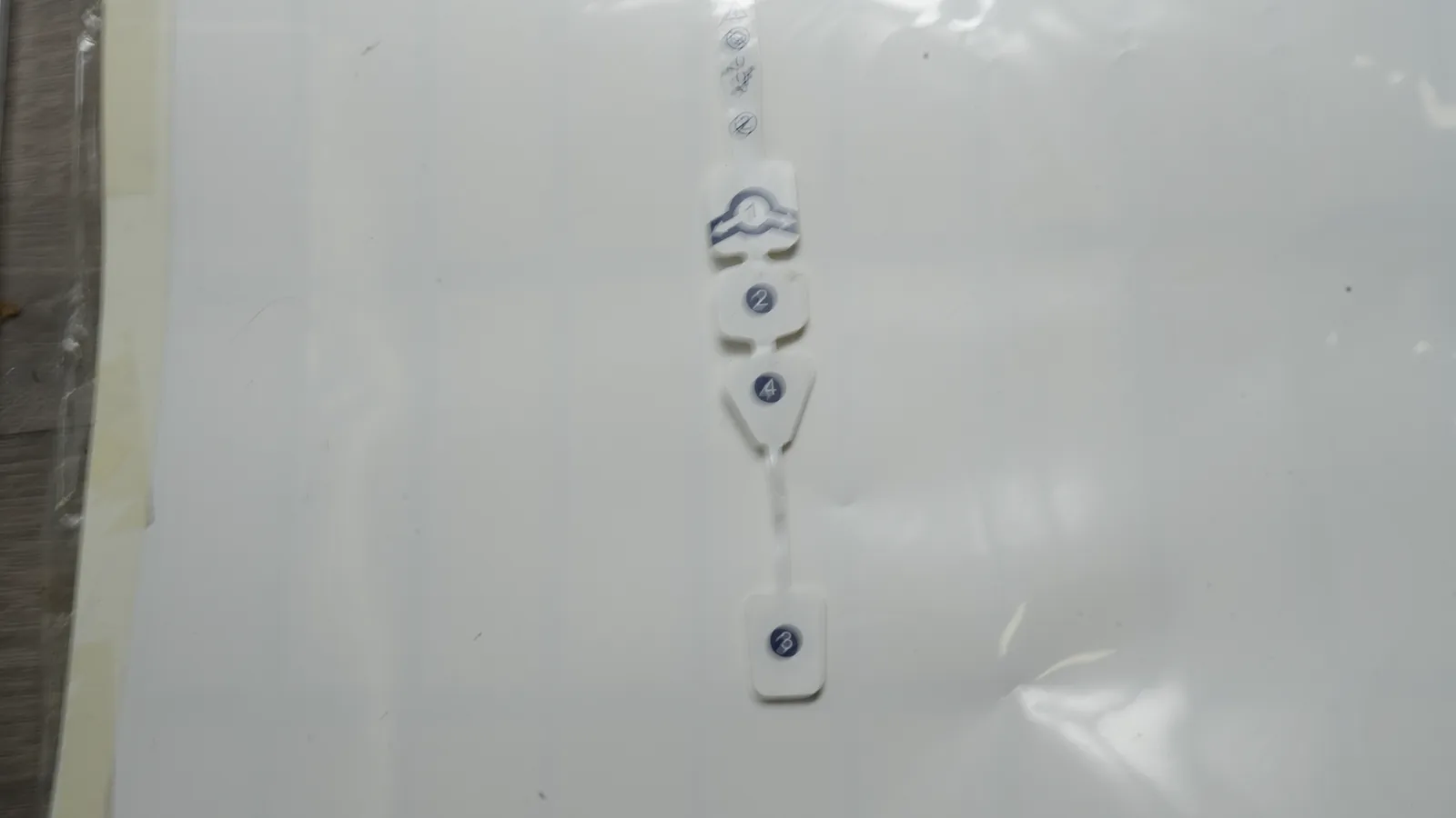
What Is a Screen-Printed Medical Electrode?
A screen-printed medical electrode uses a patterned mesh and squeegee to deposit functional ink. After curing, the film becomes part of a flexible electrode circuit. This additive process places material in the pattern instead of etching continuous copper-clad laminate.
That definition covers two related product families, not one universal construction:
- Skin-contact electrodes acquire biopotentials or deliver specified stimulation through wet or dry interfaces; ECG, EEG, EMG, TENS, and wearable arrays have different requirements.
- Electrochemical or IVD electrodes expose working, counter, and reference areas to a sample. Carbon, gold, platinum, silver, Ag/AgCl, reagents, and membranes may appear. Screen-printed biosensor electrodes differ from disposable ECG patches.
A useful generic anatomy reads from the exposed interface toward the equipment connection:
SKIN OR SAMPLE SIDE
Conductive hydrogel / dry contact / recognition chemistry application-specific
Exposed electrode area: Ag/AgCl, carbon, gold, platinum, or another system
Printed conductor: silver, carbon, or compatible conductive composition
Printed dielectric/passivation over traces; openings define active areas
Flexible substrate: treated PET/PEN, polyimide, TPU, textile, or specified film
PSA, foam carrier, backing, barrier, and release liner as specified
Contact pad, snap, lead wire, crimp, ZIF tail, or other connector
EQUIPMENT SIDE
This diagram is not a bill of materials. A PET biosensor card may put its working, counter, and reference electrodes on the same face. A wearable electrode patch may add a skin adhesive, moisture-management layers, a lead, and a flexible backing. An implantable electrode, a sterile assembly, and a powered medical system require controls beyond this generic component description.
How Screen-Printed Medical Electrodes Are Made, Step by Step
Printed electrode manufacturing should start from released requirements, not from a preferred ink. The ink, substrate, active area, connector, adhesive, packaging, and validation plan form one system. Changing a cure profile or dielectric overlap after samples are approved can alter electrical behavior, adhesion, residues, or biological-risk evidence.
1. Release the geometry, layer stack, and acceptance plan
The drawing set defines electrode shape, active areas, trace routes, insulation openings, fiducials, overall outline, connector geometry, and datums. A separate stack drawing identifies every film, ink, adhesive, gel, backing, liner, and attachment. Revision control matters because two electrodes with the same outside shape can have different exposed areas or trace widths.
The acceptance plan separates component inspection—registration, dimensions, continuity, resistance, print condition, and connector construction—from finished-device validation. FDA's ECG-electrode guidance likewise treats materials/construction, electrical performance, adhesive performance, biocompatibility, and shelf life as distinct evidence areas. That guidance is ECG-specific.
2. Select and prepare the substrate
The substrate must survive printing, curing, converting, bending, storage, and use. Treated PET is common where dimensional stability, a smooth print surface, and web handling matter. MacDermid Alpha's Autostat CT datasheet provides one example of heat-stabilized, pre-primed polyester for conductive inks and UV dielectrics. It does not prove that any PET will work.
Preparation can include incoming inspection, cleaning, static control, surface treatment, or primer verification. Contamination can cause dewetting or weak adhesion; moisture and heat history can shift dimensions. Roll production also needs web-tension and tracking control so later layers register to the first print.
3. Prepare screens, inks, and registration controls
Each layer normally has its own screen or stencil. Mesh, emulsion, snap-off, squeegee, speed, ink mixing, viscosity, and usable time affect the deposit. The released process ties controlled inputs to an output such as dried thickness, line width, resistance, or coverage.
Functional inks are not interchangeable colors. Settling, solvent loss, shear history, contamination, or an incorrect thinner can change print behavior and cured properties. Medical electrode screen printing therefore needs material identity and lot traceability, mixing instructions, environmental limits where required by the supplier, and a defined rule for material remaining after the allowed working period.
4. Print and cure the conductor and electrode layers
The first functional print may be a silver bus and trace, a carbon conductor, or another compatible layer. The electrode interface may be the same print or a later, different composition. For screen-printed Ag/AgCl electrodes, a silver or carbon conductor can sit below an Ag/AgCl contact or reference area when the selected supplier system permits that stack.
Each pass must reach its specified state before the next incompatible operation. Drying removes carrier; thermal or UV curing develops the film. Oven air temperature is not necessarily web temperature, and dwell alone does not prove energy delivered. Records may need zone settings, belt speed, UV dose, web temperature, and lot linkage.
Supplier data shows why no universal recipe is credible. DuPont 5881 gives a 280-mesh screen, 18–20 µm dry film, and 30–40 mΩ/sq/mil typical resistivity for that named Ag/AgCl composition. Those values are neither a JASPER specification nor a benchmark. A different 65/35 Ag-to-AgCl formulation and named compatible conductors. Grade identity belongs beside every process value.
Multiple passes may be needed for coverage or resistance. A peer-reviewed high-density EMG construction used three silver-conductor and two dielectric passes with intermediate drying. It demonstrates cumulative registration and thermal-history risk; it does not prescribe five passes for production.
5. Print dielectric insulation and define the active area
Dielectric or passivation ink covers conductive traces while leaving electrode faces and connector pads exposed. The printed opening can define the electrochemically or electrically active area more precisely than the conductor outline alone. It can also isolate crossing conductors in a compatible multilayer design.
The dielectric has its own adhesion, cure, flexibility, edge-coverage, and pinhole requirements. DuPont BQ10 is one UV-curable dielectric designed for polyester biosensor systems. Its existence does not establish compatibility with an arbitrary silver, carbon, PET, adhesive, or sterilization process. The material stack needs documented compatibility and, where later inspection cannot reveal latent cure or bond defects, process validation.
6. Add the skin-contact or sample-contact interface
A skin electrode may receive a conductive hydrogel, dry conductive interface, skin adhesive, foam carrier, breathable backing, or release liner. An electrochemical sensor may instead receive mediator, enzyme, membrane, electrolyte, or another recognition layer. Placement accuracy, coverage, contamination control, coating weight or geometry, and environmental exposure can matter as much as the underlying print.
This stage changes the validation burden. The contact construction includes inks, dielectric, adhesive, hydrogel, backing, residues, and packaging interactions. FDA's biocompatibility resource and ISO 10993-1:2025 frame biological evaluation around the body-contacting device within risk management. One material statement cannot replace evaluation of the finished construction and contact duration.
7. Laminate, connect, and convert the printed sheet or web
Lamination adds specified adhesives, carriers, backings, and liners. Connections may use a snap, tab, lead wire, crimp, conductive adhesive, heat seal, or printed tail. The drawing must state contact side, geometry, strain relief, mating hardware, and acceptance criteria.
Converting cuts the outline and openings by matched-tool die, rotary die, knife, laser, or another qualified method. Selection depends on the stack, edge and particulate limits, registration, heat sensitivity, and volume. The cut must reference the print datums.
Sheet processing is useful for development, changing geometries, or formats poorly suited to a web. Roll-to-roll production can link printing, drying, vision inspection, lamination, and rotary converting, but it adds web-tension, lane-registration, splice, and roll-traceability controls. Neither format is inherently “medical.” The released manufacturing process and evidence package determine control.
8. Inspect, package, and release the component
Inspection follows the drawing and control plan. Agreed checks may cover material identity, print condition, registration, dimensions, continuity, resistance, dielectric coverage, connector construction, bond strength, and packaging. A test is not a JASPER capability until the quoted scope confirms it.
Packaging must preserve the released state against moisture loss, contamination, light, oxygen, or mechanical damage as applicable. Sterility is not assumed. A sterile finished product requires qualified packaging, sterilization, and shelf-life evidence.
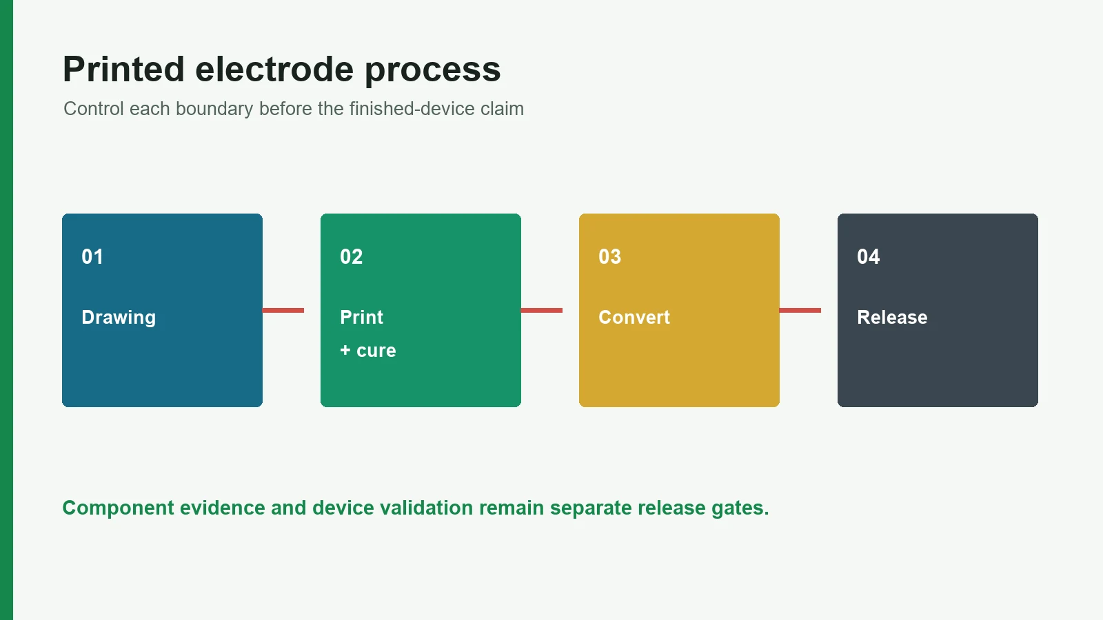
Process flow:
Released requirements
Substrate identity and preparation
Conductor/electrode printing → controlled dry or cure
Dielectric/passivation printing → controlled cure
Skin or sample interface deposition
Lamination + connector integration
Registered cutting/converting
Inspection + packaging + lot release
Finished-device verification, validation, and regulatory evidence
Materials Determine What the Process Can Deliver
Material selection starts with intended function. Ag/AgCl, silver, and carbon do different jobs; PET and TPU do not tolerate the same print or cure window; hydrogel and a dry contact surface create different patient-interface and packaging questions.
| Layer or choice | What it controls | Useful source-backed example | Decision boundary |
|---|---|---|---|
| Treated PET/PEN | Print surface, dimensional stability, web handling, thermal window | MacDermid Alpha Autostat CT is pre-primed, heat-stabilized PET for conductive inks and UV dielectrics | Flexible does not mean stretchable; verify treatment and heat history by grade |
| TPU, elastomer, textile | Conformability or engineered stretch | Research and supplier systems use stretchable inks or patterned conductors | Ink, primer, strain geometry, and cure must work as a system |
| Silver conductor | Low-resistance traces and buses | DuPont and Henkel publish screen-printable silver systems | Migration, cost, adhesion, bend, and interface compatibility remain design inputs |
| Ag/AgCl electrode layer | Biopotential contact or electrochemical reference behavior in suitable systems | DuPont 5881/5874 and Henkel EDAG PE 409 are named grade examples | Ratio and process are grade-specific; no universal performance follows from the label |
| Carbon | Working/counter electrode, protective or resistive function in suitable designs | DuPont BQ221/BQ242 target biosensor working electrodes | Surface chemistry and resistance differ from silver or Ag/AgCl |
| Dielectric/passivation | Trace insulation, active-area definition, crossover isolation | DuPont BQ10 is a UV-curable polyester biosensor dielectric | Check cure, pinholes, overlap, flexibility, and conductor/substrate compatibility |
| Hydrogel / dry interface | Skin coupling, adhesion, moisture behavior | FDA ECG guidance treats electrical, adhesive, biological, and shelf-life evidence separately | Must be evaluated in the final contact construction and intended duration |
| Connector / lead | Signal transfer and mechanical load path | Snap, tab, crimp, wire, heat seal, or printed tail are project choices | Mating geometry, strain relief, bond, and electrical acceptance require definition |
A flexible electrode circuit on PET can bend around a modest radius, but it is not automatically stretchable. Stretch changes trace geometry and local strain. A TPU or textile base also does not solve that problem alone; the conductor, dielectric, pattern, adhesive, and connection must tolerate the specified deformation.
Medical Electrode Screen Printing Needs a Released Control Matrix
A process description becomes manufacturable only when it states what is controlled, how it is recorded, and what happens if the result falls outside the limit. The table below is a planning framework, not a universal inspection plan.
| Stage | Control input | Possible production record | Why the next stage depends on it |
|---|---|---|---|
| Incoming material | Supplier, grade, lot, treatment, storage status | Certificate/lot identity; incoming check | Wrong film or aged ink can invalidate adhesion and cure evidence |
| Screen and setup | Artwork revision, mesh, emulsion, squeegee, datum | Setup verification; first-piece image/measurements | Deposit and geometry begin at the stencil |
| Ink preparation | Grade/lot, mixing, working time, environment | Batch/use log | Viscosity and dispersion affect print continuity and thickness |
| Printing | Registration, print parameters, number of passes | In-process inspection; press record | Later layers inherit first-layer position and thermal history |
| Drying/curing | Time, temperature/web temperature, belt speed, UV dose as applicable | Oven/UV record linked to lot | Under- or over-processing can alter adhesion, resistance, residue, or substrate dimensions |
| Dielectric | Overlap, openings, pinholes, cure | Vision/coverage check | Defines exposed area and insulation boundary |
| Lamination/converting | Material lot, pressure, datum, tool, cut registration | First article; dimensional report | Converts functional print into final geometry |
| Electrical/mechanical inspection | Released method and limits | Lot results; nonconformance record | Confirms specified component outputs—not clinical suitability |
| Packaging | Pouch/liner/barrier, seal or handling requirements | Packaging record | Preserves the released state through storage and shipment |
The quality and testing scope should name the method, fixture, conditioning, sample plan, units, and acceptance limit. “Resistance tested” is incomplete if the drawing does not identify the measurement path, contact method, temperature, or whether the value applies before or after converting.
A Failure Chain Is More Useful Than a Defect Label
An observed defect points to an investigation path, not a guaranteed root cause. Resistance drift, for example, can originate in deposited thickness, incomplete cure, damaged traces, connector contact, environmental exposure, or the measurement fixture.
| Observed condition | Plausible manufacturing contributors | First evidence to review | Finished-device implication |
|---|---|---|---|
| Open or intermittent circuit | Skip, pinhole, crack, cut intrusion, weak connector bond | Print image, continuity map, cut registration, bond section | Signal loss or channel dropout must be assessed in system context |
| High or variable resistance | Deposit variation, cure variation, narrow trace, contact contamination | Grade/lot, thickness proxy, cure record, four-wire/defined measurement | May affect noise, voltage drop, or stimulation current depending on circuit |
| Mislocated active area | Layer registration or converting datum error | Fiducials, overlay image, dimensional report | Changes contact or sample geometry; may invalidate performance evidence |
| Delamination or ink lift | Contamination, surface energy, incompatible cure, bending at an interface | Incoming film record, adhesion result, cross-section, environmental history | Can expose traces, shift geometry, or create particles |
| Dielectric pinhole or edge gap | Poor coverage, debris, screen damage, insufficient overlap | Backlight/vision image, screen inspection, sectioning | May expose unintended conductor or alter electrochemical area |
| Adhesive or gel out of position | Coating/dispense registration, laminate shift, converting movement | Weight/area record, vision image, liner inspection | Affects skin contact, edge seal, handling, and intended-use testing |
| Connector separation | Poor crimp/bond, inadequate strain relief, incompatible materials | Pull/bond test, section, mating-cycle record | Interrupts the signal path even when the printed circuit passes continuity |
Contain the affected lot, preserve samples, and compare records before adjusting the press or cure. Changing several parameters at once can hide the true cause and break the approved process window.
Component Inspection and Finished-Device Validation Are Different Jobs
A supplier can manufacture a dimensionally and electrically conforming printed part while the finished device still lacks the evidence needed for its intended use. The handoff must therefore identify who owns each requirement and which records cross the boundary.
| Evidence area | Component-manufacturing contribution | Finished-device responsibility | Shared decision needed |
|---|---|---|---|
| Materials and construction | Lot identity, released BOM, process records, change notice | Evaluate the final construction and supplier controls | Exact grade, processing aids, residues, substitutions |
| Dimensions and registration | Measure to released drawing | Confirm geometry supports intended use and system tolerances | Datums, active area, connector and mating stack |
| Electrical component outputs | Continuity/resistance or other agreed tests | Validate signal acquisition, stimulation, safety, or sensor performance | Fixture, conditioning, limits, aging points |
| Biological safety | Supply material/process information where available | Risk-based evaluation of the final body-contacting device under ISO 10993-1 | Contact type/duration, residues, packaging, sterilization |
| Adhesive/skin interface | Control specified adhesive/gel geometry and lots | Validate adhesion, wear, removal, skin response, use conditions | Substrate, preparation, motion, sweat, duration |
| Shelf life and packaging | Build and package to released specification | Establish labeled shelf life with aging and performance evidence | Barrier, seal, storage, hydrogel/adhesive stability |
| IEC 60601 system safety | Provide component data requested by OEM | Evaluate applicable medical electrical equipment and applied part | Intended equipment, particular standards, risk controls |
| Regulatory status | Describe supplied scope accurately | Determine classification, submission, registration, labeling, and market authorization | Whether the supplied article is a component, accessory, or finished device |
FDA's Quality Management System Regulation became effective on February 2, 2026 and incorporates ISO 13485:2016 by reference. 21 CFR 820.1 does not cover a firm making only components in the same way as a finished-device manufacturer, though FDA encourages applicable practices and retains inspection authority. An electrode or accessory capable of functioning as supplied may itself meet the finished-device definition.
ISO 10993-1:2025 addresses biological-safety evaluation within risk management for body-contacting devices. ISO 10993-18:2020 covers chemical characterization, including constituents and manufacturing residues. Neither makes an ink, adhesive, or film a universally “biocompatible” electrode.
IEC 60601-1 Edition 3.2 covers basic safety and essential performance of medical electrical equipment and systems, not a generic print process. For disposable ECG electrodes, ANSI/AAMI EC12 and FDA's ECG guidance are more specific, subject to product and jurisdiction.
When Screen Printing Is Not the Best Electrode Construction
Screen printing is not the default answer when the electrical, mechanical, chemical, or program conditions favor another process.
- Very fine, dense interconnect or multilayer routing: etched copper FPC, thin-film deposition, photolithography, or another patterned process may offer tighter features and via architecture.
- Higher current or lower conductor resistance: a printed polymer-thick-film trace may be a poor substitute for copper thickness sized to the load.
- Extreme or repeated stretch: ordinary PET and conventional inks can crack or concentrate strain; an engineered serpentine, textile, elastomeric, liquid-metal, or hybrid design may fit better.
- Heat-sensitive functional chemistry: enzymes, membranes, hydrogels, adhesives, and substrates may need low-temperature or post-print deposition.
- Constantly changing laboratory designs: cut foil, sputtered prototypes, fixtures, or commercial electrodes may reach experiments faster.
- Implant, sterile, or long-term contact without a qualified system: printing may form one layer, but materials, environment, packaging, sterilization, and regulatory controls dominate.
The construction should follow the intended function and evidence plan, not a need to use a particular press.
What to Put in the Drawing Package and Sample Approval Plan
A complete project package reduces interpretation before screens, dies, fixtures, and validation work begin.
Drawing and scope inputs
| Input | What to define |
|---|---|
| Geometry and stack | Outline, active areas, traces, openings, datums; controlled substrate, inks, dielectric, adhesive/gel, backing and liner |
| Electrical requirements | Paths, method, conditioning, limits, pinout, mating connector |
| Mechanical and contact conditions | Bend/strain, strain relief, mounting; body/sample contact type, duration, chemistry, moisture and motion |
| Converting and packaging | Cut constraints, edge/particulate limits, array/liner format; cleanliness, barrier, storage and aging inputs |
| Program boundary | Market, device classification, standards, supplier evidence, change control, prototype/pilot/repeat-production path |
Sample approval checklist
- Confirm material/ink grades and the approved BOM; appearance alone is insufficient.
- Measure print-to-print and print-to-cut registration from defined datums.
- Inspect active areas, dielectric openings, traces, adhesive/gel, edges, and connectors by the released method.
- Test electrical paths with the released fixture, conditioning, contact method, and limits.
- Exercise representative bend, mating, assembly, and handling sequences.
- Run the OEM's device-level electrical, biological, adhesive, environmental, aging, packaging, clinical, and usability work.
- Freeze the approved revision and define change-notification rules.
Teams ready to compare these inputs with a production boundary can ask JASPER to review a printed electrode manufacturing scope. The review should identify what JASPER would supply and inspect, what evidence would accompany the lot, and what remains with the finished-device program before any quotation or sample approval.
Frequently Asked Questions
How are screen-printed medical electrodes made?
They are made by preparing the substrate, printing and curing conductor, electrode, and dielectric layers, adding the skin or sample interface, laminating, connecting, converting, and inspecting to released requirements. Finished-device validation follows separately.
What is the difference between a printed conductor and the electrode area?
The conductor links the active area to the connector. The electrode interfaces with skin or a sample and may use Ag/AgCl, carbon, gold, platinum, or another system. Multilayer designs often optimize the two roles separately.
Why is Ag/AgCl used in some printed medical electrodes?
Ag/AgCl suits specified biopotential and electrochemical-reference systems because it behaves differently from a plain silver trace. Formulation, underlying conductor, electrolyte or hydrogel, active area, cure, and test method determine performance.
Can a flexible electrode circuit stretch?
Not necessarily. PET can bend yet crack in tension. Stretchability needs a compatible substrate, conductor, dielectric, pattern, interfaces, and strain relief. Specify strain direction, magnitude, cycles, radius, temperature, and acceptance method.
What does the dielectric layer do in printed electrode manufacturing?
The dielectric insulates traces and defines electrode and connector openings. Its overlap, adhesion, pinholes, flexibility, and cure affect functional geometry, so it must be validated with the selected conductor and substrate.
Is there one standard curing temperature for medical electrode screen printing?
No. Cure depends on the named ink, film deposit, substrate, oven or UV system, line speed, and adjacent materials. A value copied from another ink or paper can under-cure one layer or damage another.
Which tests belong at the component manufacturer?
The released scope may assign identity, dimensions, registration, visual, continuity, resistance, dielectric, bond, connector, and packaging checks to the component manufacturer. Biological safety, clinical function, shelf life, and system safety remain finished-device evidence.
Does a conforming printed electrode component make the medical device approved?
No. Component conformity does not establish clearance, biological safety, clinical performance, or equipment compliance. The finished-device manufacturer determines applicable FDA, ISO, IEC, ANSI/AAMI, and market requirements and validates the final intended use.
Technical References
- Source: FDA Use of ISO 10993-1 Biological Evaluation Guidance. Accessed 2026.
- Source: ISO 10993-1:2025 Biological Evaluation of Medical Devices. Accessed 2026.
- Source: ISO 14971:2019 Medical Device Risk Management. Accessed 2026.
- Source: FDA Design Control Guidance for Medical Device Manufacturers. Accessed 2026.
- Source: FDA's ECG-electrode guidance. Accessed 2026.
- Source: MacDermid Alpha's Autostat CT datasheet. Accessed 2026.
- Source: DuPont 5881. Accessed 2026.
- Source: DuPont 5874. Accessed 2026.
- Source: peer-reviewed high-density EMG construction. Accessed 2026.
- Source: FDA's biocompatibility resource. Accessed 2026.
- Source: ISO 10993-1:2025. Accessed 2026.
- Source: FDA's Quality Management System Regulation. Accessed 2026.
- Source: 21 CFR 820.1. Accessed 2026.
- Source: ISO 10993-18:2020. Accessed 2026.
- Source: IEC 60601-1 Edition 3.2. Accessed 2026.
- Source: ANSI/AAMI EC12. Accessed 2026.
Review the complete electrode manufacturing scope
Send the current drawing, material stack, electrode roles, connector, use conditions, acceptance methods, program phase, and annual volume.