
Seat belt reminder sensor integration is the engineered chain that converts independent occupancy and buckle inputs—plus vehicle state, diagnostics, and timing—into a valid warning request. It is a system function, not a property of one pressure mat or buckle switch.
JASPER certifications: ISO 9001, ISO 13485, IATF 16949, and ISO 14001.
For OEM seating teams, this integration decision assigns each input, preserves unknown and fault states, and defines the evidence needed at component, installed-seat, controller, and vehicle levels. It is written for seat, electronics, validation, and technical-sourcing engineers. A seat mat may supply occupancy evidence. A separate buckle switch reports latch status. The vehicle program owns activation conditions, warning timing, diagnostics, functional-safety activities, and compliance. This guide sets those boundaries and the approval package; it does not create a universal occupant threshold or certify one sensor against a vehicle rule.
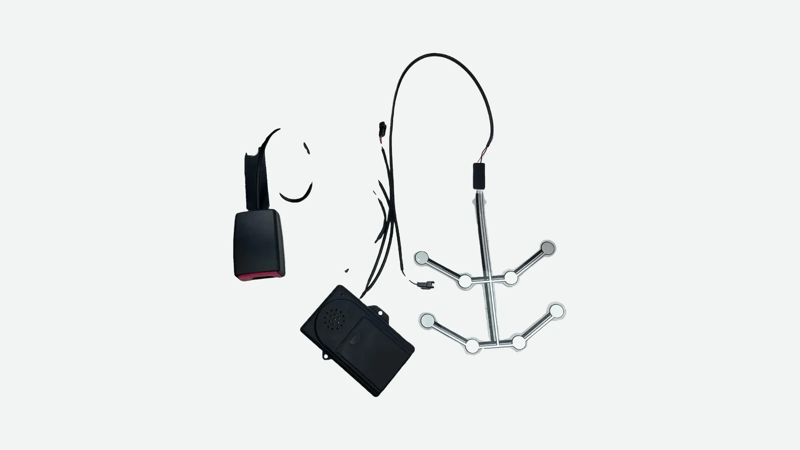
JASPER's seat belt reminder occupancy component is one manufacturing option for a defined seat input. The product scope covers the seat-integrated sensing component, not the buckle switch, ECU, telltale, chime, vehicle software, or homologation unless a controlled project document says otherwise.
Definition and System Boundary for Seat Belt Reminder Sensor Integration
A seat-belt reminder system compares evidence about belt use with the operating context in which a warning is permitted or required. Occupancy may be one input, but it is not always mandatory. The architecture can include a contact mat, an analog force-sensitive resistor, a multi-zone mat, a conditioned occupancy module, structural sensing, or another approved detection method. The buckle input can come from a mechanical contact, Hall-effect device, reed switch, or conditioned module. The controller—not either sensing element—turns those inputs into a reminder state.
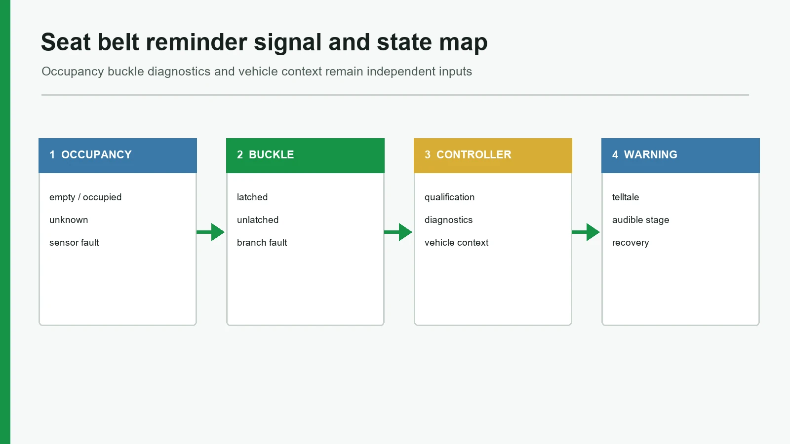
The boundary is easiest to review as a signal chain:
Seat load and installed cushion stack
▼
Occupancy sensing element · ► interface circuit · ► valid / unknown / fault
Buckle tongue and latch · ► buckle switch
Ignition / propulsion / speed / seat configuration
▼
vehicle or seat controller
▼
telltale / audible warning / log
This chain creates four evidence layers. Mixing them is a common cause of approval disputes.
| Layer | Decision owned | Typical evidence | What the evidence cannot prove by itself |
|---|---|---|---|
| Sensor component | Geometry, zones, tail, pinout, raw output, basic open/short behavior | Controlled drawing, continuity or resistance records, dimensions, connector checks | Installed-seat classification or final warning behavior |
| Installed seat | Load transfer through trim, foam, heater, protection layer, sensor, and support | Representative seat builds, positions, loads, transitions, repeated installations | Vehicle context, telltale timing, or legal compliance |
| Controller and network | Measurement circuit, valid ranges, thresholds, diagnostics, state timing, communication | Schematics, sampled data, fault injection, software and calibration versions | Physical seat durability or complete vehicle approval |
| Vehicle | Applicable positions, activation conditions, warning response, service behavior, market requirements | Vehicle tests, regulatory records, assessment results, released requirement set | A transferable component rating for another seat or program |
JASPER's component testing and validation planning page makes the same distinction: component checks answer defined production or application risks, while the OEM or Tier 1 retains the installed-seat and vehicle decisions. A continuity result is useful. It is not a seat-classification accuracy result.
Build Seat Belt Occupancy Logic Around Independent Inputs
Seat belt occupancy logic should begin with a state contract, not with an occupied AND unbuckled code fragment. The contract names every accepted input, the validity of that input, the vehicle context, the resulting request, and the evidence owner. It must preserve uncertainty. Otherwise, a disconnected line can silently become empty, or an intermittent buckle can look like a legitimate transition.
Keep the buckle and occupancy sensor signals independent
The occupancy input answers whether the installed seat meets the program's occupied-state rule. The buckle input answers whether the latch mechanism reports the belt tongue as inserted. A Hall buckle sensor can provide a two-state buckle input, while a membrane SBR sensor can provide a load-actuated film-and-spacer occupancy input. They are separate devices with separate failure modes.
Never infer one state from the other. An empty seat can be buckled. Cargo can load an unbuckled seat. A passenger can sit without latching the belt. A loose connector can make either signal unavailable. American Honda documents one front-passenger example in which a seat weight sensor and a separate buckle sensor contribute to the reminder response, which illustrates the two-input boundary without defining a universal architecture (Honda Information Center).
Use a state table that includes unknown and fault
The table below is a design-review starting point, not a universal warning requirement. The OEM must replace every program-defined cell with the approved response.
| Seat condition | Occupancy input | Buckle input | Input validity | Controller decision boundary | Required evidence |
|---|---|---|---|---|---|
| Confirmed empty | Empty | Latched or unlatched | Valid | Program-defined empty-seat behavior | Empty builds, release margin, state log |
| Occupied and buckled | Occupied | Latched | Valid | No unbuckled reminder request | Occupant positions, latch transition, output log |
| Occupied and unbuckled | Occupied | Unlatched | Valid | Reminder request only when vehicle activation conditions are met | State, timing, telltale, and audible records |
| Object or nuisance load | Empty, occupied, or ambiguous by approved rule | Usually unlatched | Valid or ambiguous | Apply the documented classification; do not invent a person/object promise | Defined objects, positions, seat builds, acceptance rule |
| Transition or startup | Not yet qualified | Any | Unknown | Hold, inhibit, or use an approved fallback | Initialization, timeout, and recovery traces |
| Occupancy electrical fault | Implausible, open, short, or unavailable | Any | Invalid | Diagnostic and project-defined fallback; never fabricated certainty | Fault injection and recovery evidence |
| Buckle electrical fault | Empty or occupied | Implausible, open, short, or unavailable | Invalid | Diagnostic and project-defined fallback | Buckle-line fault and recovery evidence |
| Seat/configuration mismatch | Input may appear normal | Input may appear normal | System context invalid | Configuration response before normal reminder logic | Seat identity, removable-seat, coding, and network evidence |
Unknown and fault are not synonyms. Unknown means the controller lacks enough valid evidence to publish a normal state, often during startup or requalification. Fault means a defined electrical, plausibility, timing, or configuration rule has failed. Recovery can move from fault to unknown and only then to empty or occupied. That sequence prevents a brief, unsupported claim of certainty.
Decide whether occupancy input is required at all
The current U.S. Rule is a useful boundary test. The April 6, 2026 NHTSA interim final rule makes the new front and rear FMVSS No. 208 warning requirements mandatory on September 1, 2028; the rear start-of-trip visual-warning route can use buckle status without occupant detection (91 FR 17144 / FR Doc. 2026-06614). Occupancy detection may still support a customer feature, an audible warning, a rating target, or another market. It is not automatically required for the basic U.S. Rear-seat route.
That distinction can remove an unnecessary mat, tail, connector, diagnostic path, threshold, and validation campaign. For automotive application planning, document the market, seating position, warning route, and requirement owner before selecting the sensing construction.
Seat Reminder Sensor Design Starts With the Installed Seat
Seat reminder sensor design is a load-path problem before it is a software problem. The occupant does not press a bare sensing element with a controlled platen. Trim tension, seams, foam thickness and stiffness, heater or ventilation layers, protection films, cushion contours, and the support structure redistribute the load. A design that switches cleanly on a bench can miss an occupant after installation—or stay active after the occupant leaves.
Foil-sensor examples above or below the cushion. Those examples establish that more than one placement exists; they do not establish which placement fits a particular seat. The seat drawing must define the program's surface terminology, sensor datum, orientation, tail exit, protected bend area, and allowed stack change.
| Placement or architecture | Main advantage | Main integration risk | Evidence needed before selection |
|---|---|---|---|
| Near the trim or upper cushion surface | Shorter, more direct load path | Trim seams, heater features, occupant feel, local damage, and cover tension can dominate | Seat sections, trim map, heater geometry, local-load and durability trials |
| Below the main cushion | Better physical protection and simpler trim interface | Foam spreads the load and can reduce separation between required states | Cushion stiffness/contour data, position map, temperature and aging builds |
| Pocketed or embedded within foam | Sensor can follow a controlled cavity | Foam cutting, adhesive, pocket depth, and assembly variation become process inputs | Released work instruction, cavity dimensions, repeat builds, removal inspection |
| Structural load sensing | Better route when force or mass-related information must pass through a defined structure | Brackets, load paths, calibration, temperature compensation, and cost increase | Structural model, calibration method, tolerance stack, complete seat validation |
| Capacitive, radar, camera, or fused sensing | Can add human-presence or classification evidence without relying only on cushion load | Electromagnetic environment, occlusion, privacy, algorithm, and system complexity | Architecture-specific performance, diagnostic, cybersecurity, and system evidence |
Develop thresholds from installed distributions
The project should define required empty cases, required occupied cases, nuisance objects, occupant positions, seat adjustments, foam and trim revisions, temperature conditions, and release behavior. Measure those cases on representative seats. Then place activation and release limits inside a verified separation region.
One catalog force is not an occupancy threshold. It describes how a named element responded under its test fixture. The installed seat adds a mechanical transfer function, while the interface circuit adds electrical tolerances and the controller adds state logic. A threshold therefore needs its units, signal direction, circuit, seat build, sample population, test pose or surrogate, environment, and acceptance margin.
Use the seat occupancy sensor mat manufacturing case as a component-scope reference: it can show geometry, zones, traces, tail, cable, connector, and controlled production records. It does not prove an occupant threshold, classification accuracy, warning result, durability target, or vehicle approval.
Give hysteresis, debounce, qualification, and diagnostics different jobs
These controls solve different problems. Combining them under one filter setting hides faults.
| Control | Intended job | Required project input | What it must not conceal |
|---|---|---|---|
| Hysteresis | Use different activation and release boundaries so noise near one limit does not create repeated state changes | Rising/falling signal distributions and margin | Overlap between steady empty and occupied cases |
| Debounce | Reject brief contact bounce or short transitions | Measured pulse duration, sampling, acceptable latency | Persistent intermittency, a loose terminal, or a poor load path |
| State qualification | Require a valid candidate state for a defined condition before the controller reports it | Valid-sample rule, timer start/reset, timeout, startup behavior | Invalid or missing samples counted as valid evidence |
| Diagnostic rule | Detect open, short, out-of-range, stuck, implausible, or configuration conditions | Circuit topology, valid and diagnostic bands, fault time, recovery rule | A convenient fallback presented as a measured normal state |
Texas Instruments' Schmitt-trigger guidance explains the upper/lower threshold principle. Microchip AN2805 shows why debounce timing must be selected from the pulses the design needs to reject. Neither source sets an automotive seat value. The OEM or controller owner must derive timing from measured seat and electrical behavior, then verify that the added latency still meets the warning requirement.
The stop condition is simple. If steady empty and occupied distributions overlap after representative mechanical and environmental variation, a longer debounce does not create information. Change the sensing zone, the cushion load path, the element, the circuit, or the system's input set.
Trace the mechanical failure chain
Foam, trim, heater, sensor position, or support changes
load transfer or empty preload shifts
raw signal margin shrinks or transitions become unstable
occupancy state is late, false, missed, unknown, or faulty
reminder request and diagnostic response depart from the approved contract
Reopen the affected evidence after any change to the foam, cover, heater, support, sensor zone, adhesive, tail, connector, circuit, threshold, debounce, or software state rule. A statement that the sensor part number did not change is insufficient when the installed load path did.
Treat the Harness and Connector as a Diagnostic Boundary
A valid sensing element can still produce the wrong system state at the tail, terminal, connector, seat harness, return path, or controller input. Treat that interconnect as part of the measured circuit. Two wires and occupancy signal are not interface specifications.
The controlled drawing should name:
- every pin and electrical function;
- the mating connector and terminal;
- signal and return routing;
- tail length, exit direction, bend limits, and strain relief;
- valid empty, occupied, and transition ranges;
- open, short-to-return, short-to-supply, and cross-line behavior where applicable;
- connector-present or seat-present detection, if used;
- sample rate, input protection, pull-up or current source, and diagnostic bands;
- startup, disconnection, reconnection, fault setting, and recovery behavior; and
- folding, sliding, removable, service, and manufacturing configurations.
Do not debounce a damaged interconnect into a normal state
An intermittent open may resemble rapid empty/occupied transitions. Extending debounce can suppress the visible chatter while leaving the defect in place. That produces a slower symptom, not a repaired circuit.
Unsupported tail or weak terminal retention
intermittent open during seat motion
alternating valid-looking and invalid samples
overlong debounce masks the sequence
late reminder, stale state, or delayed diagnostic
Record raw input validity, candidate state, qualified state, diagnostic state, buckle status, vehicle context, and output on one time base. The sequence then shows whether a warning error began in the mechanics, interconnect, circuit, state logic, or vehicle response.
Define removable and folding-seat behavior
The 2026 NHTSA rule includes electrical-connection provisions for readily removable rear seats: connections must be established automatically or use readily accessible manual connectors, with a driver-visible warning for an improper connection under specified architectures (FR Doc. 2026-06614). The rule does not dictate a universal pinout, terminal, diagnostic current, or DTC.
The state contract must distinguish seat installed and connected, installed but disconnected, removed by an approved method, folded or stowed, and reinstalled but not yet qualified. A permanent pull-up that makes every disconnected seat look empty destroys that distinction. Configuration evidence should decide whether the input is absent by design or missing because of a fault.
Separate Regulation, Assessment, and Validation Evidence
Regulations and rating protocols define vehicle warning behavior and test conditions; they do not supply a universal mat force threshold or debounce value. Those values must be allocated by the OEM or Tier 1 from the seat stack, occupant and object data, signal noise, controller logic, and validation evidence.
| Reference | Level and purpose | Useful integration question | It does not prove |
|---|---|---|---|
| FMVSS No. 208 / 49 CFR 571.208 | U.S. Vehicle safety standard, including current and future-effective warning provisions | Which vehicles, positions, dates, inputs, and warning tests apply? | That one mat, buckle switch, or connector is compliant |
| UN Regulation No. 174 | Vehicle-type approval for safety-belt reminders under the 1958 Agreement | Which seating positions, warning levels, removable-seat connections, and transitional provisions apply? | Component approval; the SBR provisions formerly associated with UN R16 now sit in the dedicated vehicle regulation (UNECE Addendum 173) |
| IIHS SBR protocol | Independent U.S. Consumer rating | What vehicle warning performance will the rating procedure examine? | A legal requirement or component certification (current IIHS protocol) |
| Euro NCAP Occupant Monitoring v1.2 | July 2026 consumer-assessment protocol | How are seat-belt use, correct routing, and rear occupancy assessed? | Type approval or a transferable sensor threshold (v1.2 protocol) |
| ISO 26262-2:2018 | Functional-safety management for safety-related road-vehicle E/E systems | Which lifecycle, item, responsibility, change, and confirmation activities apply? | Nominal performance, a fixed ASIL, or a sensor calibration (ISO scope) |
| ISO 16750-3/-4:2023 | Mechanical and climatic load frameworks tied to mounting location | Which project loads, states, severities, sequences, and acceptance criteria are needed? | A blanket passes ISO 16750 claim (Part 3; Part 4) |
| ISO 20653:2023 | Road-vehicle electrical-equipment enclosure IP codes and confirmation tests | What is the defined enclosure and required protection level? | An automatic IP rating for a flexible mat or the entire seat (ISO scope) |
The cited ISO editions can enter revision processes. Recheck their current status and the applicable vehicle rules before release.
Use one validation matrix across all owners
| Evidence layer | Minimum test families | Controlled inputs | Release boundary |
|---|---|---|---|
| Component | Drawing, dimensions, continuity/raw output, pinout, tail and connector checks, agreed environmental screens | Part revision, fixture, circuit, sample and lot identity | Releases only the defined component |
| Installed seat | Empty, occupied, nuisance object, position, ingress/egress, adjustment, folding, repeated builds, foam/trim variants | Seat BOM/revision, stack, installation instruction, surrogate or occupant definition, environment | Releases occupancy-state evidence for that seat build |
| Controller and interface | Thresholds, hysteresis, debounce, startup, open/short/intermittent injection, timeout, recovery, network loss | Hardware, software, calibration, harness, sampled raw and qualified states | Releases state and diagnostic behavior for that configuration |
| Vehicle | Buckle/occupancy/context combinations, telltale and audible response, removable-seat behavior, market tests, service recovery | Vehicle variant, position, market, rule/protocol edition, software and calibration | Releases the vehicle warning function; the legally responsible manufacturer retains compliance evidence |
The matrix should record input, validity, candidate state, qualified state, buckle state, diagnostic state, vehicle context, and warning output on the same timeline. It turns a failed warning into a traceable layer and owner instead of an argument between suppliers.
Run the OEM Integration and Sample-Approval Process
A practical integration process closes decisions in dependency order. Skipping directly from a sensor drawing to a vehicle warning test makes every late failure expensive.
- Freeze the requirement route. Record market, vehicle class, seating position, warning objective, applicable rule or rating protocol, compliance date, and requirement owner. Decide whether occupancy evidence is needed.
- Issue the seat and state package. Provide the cushion section, trim and foam revisions, datums, sensor envelope, load cases, buckle states, vehicle context, unknown/fault behavior, and acceptance owner.
- Release the electrical interface. Define pinout, mating connector, valid/diagnostic bands, circuit, sampling, thresholds, hysteresis, debounce, timeout, network behavior, and recovery.
- Build representative seats. Use production-intent trim, foam, heater or ventilation layer, support, harness route, connector support, and assembly instruction. Bare-element pressing is a component screen, not seat approval.
- Execute the synchronized matrix. Run normal states, nuisance loads, transitions, environmental conditions, open/short/intermittent faults, removable-seat configurations, and change cases while logging the complete timeline.
- Approve each layer and control changes. Close component, seat, controller, and vehicle evidence separately. Link every later material, process, supplier, geometry, circuit, calibration, or software change to the evidence that must be repeated through engineering change control.
Drawing and sample-approval checklist
Disqualify an incomplete package when it substitutes a catalog force for installed-seat data, labels a disconnected input as empty, uses debounce to hide intermittency, omits the mating connector, treats one seat build as all variants, or asks a component report to prove the final warning. Mark an unknown field openly. An assigned open item is safer than a silent assumption.
When an Occupancy Mat Is Not the Best Architecture
A thin occupancy mat fits when the required states can be separated through the real cushion stack and the controller can diagnose the proposed interface. It is not the default answer for every reminder.
Do not choose it when the approved rear-seat route needs only buckle status; the requirement is calibrated structural load or absolute mass; the steady empty and occupied distributions overlap; the seat applies uncontrolled folding, shear, or preload; the function needs human/object classification that the load signal cannot support; or an existing vehicle input supplies the decision with less hardware and validation.
The alternatives include a buckle-only status architecture, structural load cells, capacitive electrodes, in-cabin radar or camera sensing, and multi-input fusion. Compare the broader car seat occupancy sensor architectures against the required output, not against the product name.
Frequently Asked Questions
What does seat belt reminder sensor integration include?
It includes the occupancy input, buckle input, measurement circuit, validity and diagnostic rules, vehicle context, state qualification, warning request, and validation evidence. The sensor mat is only one possible occupancy component. The vehicle controller and manufacturer retain the final logic, warning behavior, and compliance record.
Does FMVSS No. 208 require rear-seat occupancy detection?
No. The April 2026 NHTSA interim final rule allows the U.S. Rear start-of-trip visual-warning route to use buckle status without occupant detection. Occupancy detection may support other warning features, rating targets, or markets, but it is not automatically required for that basic rear-seat route.
What is the difference between a buckle and occupancy sensor?
An occupancy sensor reports evidence that a seat is occupied under an approved seat-state rule. A buckle sensor reports whether the belt tongue is latched. The inputs are independent: a seat may be empty and buckled, occupied and unbuckled, loaded by an object, or affected by an electrical fault.
How should seat belt occupancy logic handle unknown and fault states?
Unknown should mean that valid evidence is not yet sufficient, such as during startup or requalification. Fault should mean that an electrical, plausibility, timing, or configuration rule failed. The controller should apply the approved fallback and diagnostic response rather than relabel either condition as a certain empty or occupied state.
Is there a universal trigger weight for a seat reminder sensor design?
No. The installed trim, foam, heater, support, sensing zone, circuit, occupant position, object cases, and environment change the relationship between occupant mass and sensor signal. Regulatory test-subject values are not component thresholds. Derive activation and release limits from representative installed-seat distributions.
What is the difference between hysteresis and debounce?
Hysteresis separates activation and release thresholds; debounce rejects brief transitions over time. Neither repairs overlapping steady-state data or a damaged interconnect. The project must set both from measured signals, then verify that filtering does not mask real transitions, delay the warning improperly, or suppress diagnostics.
Which standards apply to seat belt reminder sensor integration?
Start with the vehicle market's current warning rule, such as FMVSS No. 208 or UN Regulation No. 174. Treat IIHS and Euro NCAP as assessment protocols. ISO 26262, ISO 16750, and ISO 20653 can frame lifecycle, environmental, and enclosure work, but none automatically approves a sensor.
What should an OEM send for a seat and buckle sensor review?
Send the seat section and BOM revision, sensing envelope and datums, occupancy and buckle state contract, nuisance cases, connector and pinout, circuit assumptions, thresholds and timing ownership, fault strategy, environmental conditions, sample builds, validation matrix, production evidence, and change-control requirements. Mark undecided fields explicitly.
Review Seat and Buckle Sensor Requirements
Prepare one controlled package containing the seat section, load cases, state table, buckle interface, tail and harness route, mating connector, measurement circuit, diagnostic concept, sample plan, and evidence ownership. Then send the controlled seat drawing for a component-scope review. The first decision should be whether occupancy evidence is needed and whether the installed seat can separate the required states.
Technical References
- Source: NHTSA FMVSS No. 208 occupant crash protection. Accessed 2026.
- Source: UN Regulation No. 174 safety-belt reminders. Accessed 2026.
- Source: ISO 26262 road-vehicle functional safety. Accessed 2026.
- Source: ISO 16750 mechanical and climatic conditions. Accessed 2026.
- Source: ISO 20653 road-vehicle enclosure protection. Accessed 2026.
- Source: Littelfuse's Hall buckle-sensor data sheet. Accessed 2026.
- Source: HDK's membrane SBR sensor sheet. Accessed 2026.
- Source: Honda Information Center. Accessed 2026.
- Source: 91 FR 17144 / FR Doc. 2026-06614. Accessed 2026.
- Source: IEE's SBR page. Accessed 2026.
- Source: Texas Instruments' Schmitt-trigger guidance. Accessed 2026.
- Source: FR Doc. 2026-06614. Accessed 2026.
- Source: UNECE Addendum 173. Accessed 2026.
- Source: current IIHS protocol. Accessed 2026.
- Source: v1.2 protocol. Accessed 2026.
- Source: ISO scope. Accessed 2026.
- Source: Part 3. Accessed 2026.
- Source: Part 4. Accessed 2026.
- Source: FSR 400 Series data sheet. Accessed 2026.
Define occupancy and buckle states together
Send the seat section, state table, buckle interface, harness route, circuit, diagnostics, sample plan, and evidence ownership.