
Silicone keypad hardness selection should begin with the required force-travel curve, return margin, sealing load, temperature range, and time under compression—not with a universal Shore A number. This guide is for OEM design, quality, and sourcing teams. It shows how to screen compounds and geometry, then sets the decision boundary: release the molded keypad only after ASTM D395 or ISO 815 data have been interpreted alongside production-intent assembly tests.
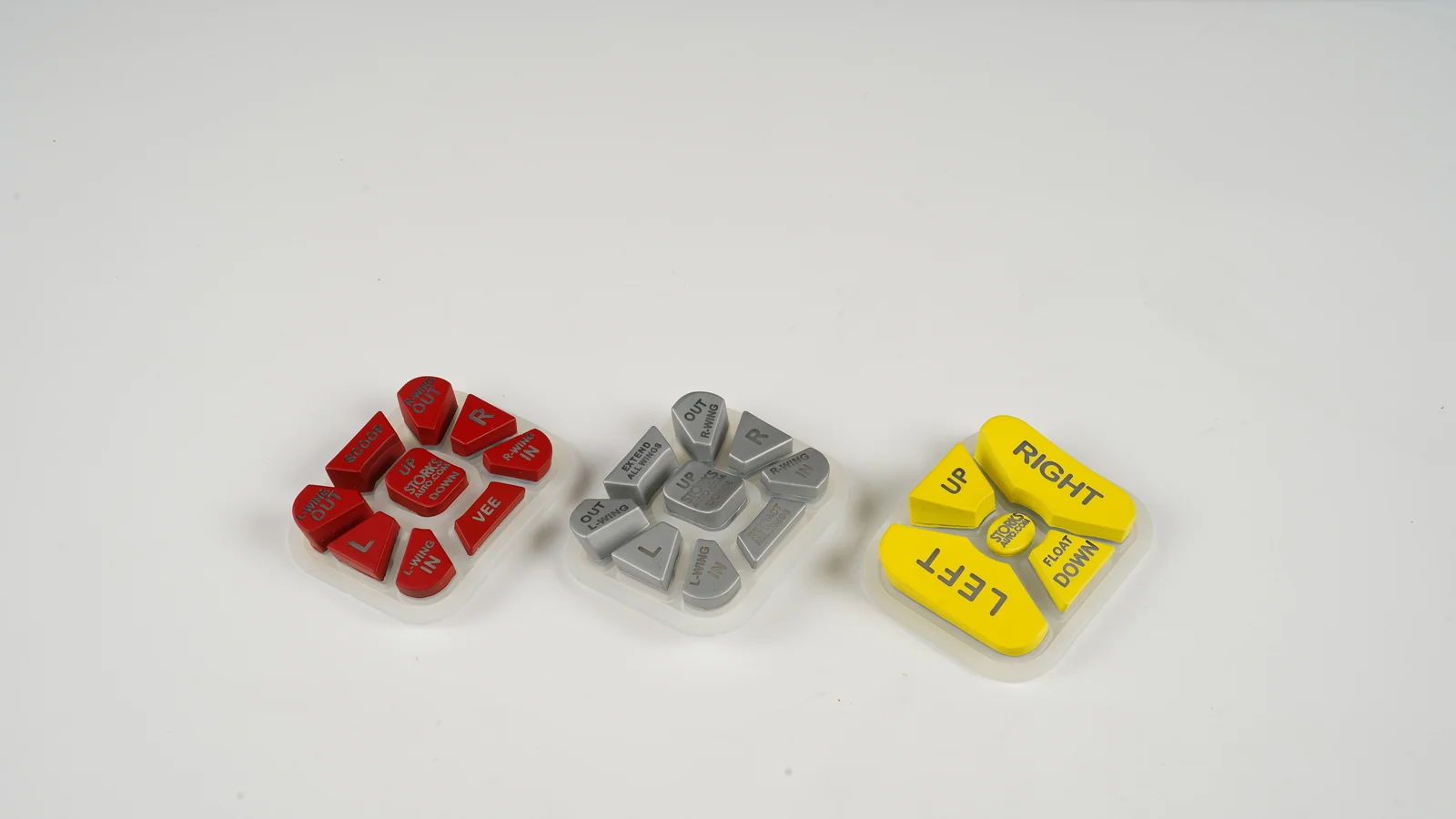
For silicone rubber keypads, hardness is a controlled material input. It is not a complete key-feel specification. A 50 Shore A plaque, a thin molded web, a compressed perimeter seal, and a finished key inside a fastened bezel answer different questions. The useful selection process keeps those questions separate until prototype evidence connects them.
1. Why Hardness Alone Is an Expensive Shortcut
Selecting a keypad from hardness alone can produce a part that passes incoming inspection and still sticks, double-acts, loses sealing preload, or feels wrong in the enclosure. Shore A describes resistance to a standardized indentation. The user presses a three-dimensional mechanism whose response also comes from the web profile, key height, travel stop, vent path, contact architecture, PCB support, bezel clearance, and assembly compression.
The common failure chain is not complicated:
temperature + sustained assembly load + dwell time
compound response + web/base/seal geometry
permanent set and/or loss of counterforce
less key return, reduced contact separation, or lower seal margin
intermittent input, a slow or sticking key, or leakage at the assembly boundary
That chain contains at least four measurements. Treating them as synonyms hides the failure mechanism.
| Measurement | What it reports | What it does not prove |
|---|---|---|
| Shore A hardness | Indentation response of a conditioned rubber specimen under a named durometer method | Finished-key actuation force, click ratio, return force, or life |
| Force-travel curve | Peak force, contact force, travel, return path, and hysteresis for a defined key and fixture | Long-term recovery after static compression unless the curve is repeated after conditioning |
| Compression set | Dimensional recovery after a specimen is held under a stated compression, temperature, time, and recovery protocol | Dynamic cycle life or retained counterforce by itself |
| Compression stress relaxation | Change in counterforce while a specimen remains at constant deformation | The complete tactile response of a molded key in its enclosure |
ASTM D395-18(2025) defines the applicable static-compression boundary. Its compression-set methods are mainly applicable to static compressive service; repeated deformation is represented more closely by compression-flexing or hysteresis tests. A keypad base trapped under a bezel may have a static-set problem. The moving web has a cyclic force-travel problem. A sealing lip may have both a set problem and a retained-force problem.
The practical cost of the shortcut appears late. Changing a compound after tooling may change fill, shrinkage, demolding, pigment response, and force. Changing the web after appearance approval may require tool steel work and another sample loop. It is cheaper to define the outputs separately, screen controlled variants, and approve the installed system than to ask a supplier for “a harder rubber” after a poor first article.
Use the observed symptom to choose the next measurement instead of changing durometer by reflex:
| Observed symptom | Coupled variables to inspect | Next useful evidence |
|---|---|---|
| New parts feel correct; return slows after a hot dwell | Cure state, web strain, static set, counterforce loss | Baseline/post-dwell force-travel plus ASTM D395 or ISO 3384 evidence, as applicable |
| Perimeter sealing margin falls after clamped storage | Stack tolerance, seal squeeze, compound recovery, stress relaxation | Conditioned set/counterforce data followed by assembly-level sealing validation |
| Key-to-key force scatter is high | Web dimensions, cure uniformity, venting, PCB support, fixture alignment | Dimensional results and matched force-travel curves by key location |
| A loose keypad passes; the installed keypad feels heavy | Bezel clearance, fastener load, PCB position, hard stop, base compression | Curves from the released assembly at minimum and maximum stack conditions |
2. Engineering Definitions: Shore Hardness, Compression Set, and Return
The three material terms that matter most are related, but none can substitute for another. A defensible rubber keypad material selection records the test method and conditions beside each result, then verifies the finished mechanism separately.
Silicone rubber Shore hardness is an indentation result
ASTM D2240-15(2021) defines durometer hardness as an empirical penetration measurement. The result depends on elastic modulus, viscoelastic behavior, indenter geometry, and applied force; it has no simple relationship to a fundamental material property. That is why “60 Shore A” is incomplete unless the drawing or inspection plan also controls the method, scale, specimen or approved coupon, conditioning, measurement location, and reading protocol.
ISO 48-4:2018 assigns the A scale to rubber in the normal-hardness range. It assigns AM to thin normal-hardness pieces, AO to low-hardness or cellular rubber, and D to high-hardness rubber. Those scales should not be casually converted or compared. For a thin, curved, textured, or multi-level keypad, the parties should agree whether hardness is verified on a standard specimen, a co-cured witness coupon, or another controlled location permitted by the governing procedure.
Keypad compression set is a conditioned recovery result
Compression set reports how much of an imposed deflection remains after release and a specified recovery interval. Using the common constant-deflection expression:
Compression set (%) = (t0 − tr) / (t0 − ts) × 100
- t0 is original thickness.
- ts is spacer or compressed thickness.
- tr is recovered thickness after the specified recovery interval.
The Parker O-Ring Handbook illustrates the same equation: 0% means full dimensional recovery, while 100% means the specimen recovered no farther than the compressed thickness. That explanation does not create a keypad acceptance limit.
ISO 815-1:2019 requires the test conditions to remain attached to the result. Set changes with the time and temperature of compression and with the time, temperature, and conditions of recovery. Its normal constant strain is 25%, with lower strains for high-IRHD rubber. IRHD is not Shore A. ISO also distinguishes short elevated-temperature tests, typically 24 hours for cure state or classification, from longer tests, typically 1,000 hours, that include more ageing. A bare statement such as “compression set: 20%” is therefore not comparable evidence.
Stress relaxation measures retained counterforce
A sealing flange can keep roughly the same compressed height while its reaction force decays. Compression set will not fully describe that loss. ISO 3384-1:2024 measures the decrease in counterforce while rubber is held at constant deformation and constant temperature. ISO 3384-2:2019 extends the counterforce question to temperature cycling.
Neither method replaces a finished-key force-travel curve. Shin-Etsu Polymer’s force-travel guidance attributes peak force and contact force jointly to silicone material and dome shape; travel also depends on geometry and contact position. For keypad approval, record both the downstroke and return path at a defined speed, fixture, key location, temperature, and conditioning state.
Primary supplier data show why hardness is not a compression-set ranking
The examples below are useful because the grades and test conditions are named. They are typical supplier data, not specifications, JASPER results, or universal keypad limits. Rows with different methods, cure states, temperatures, or geometries must not be ranked against one another.
| Primary supplier example | Reported hardness | Reported compression-set condition and result | What the example establishes |
|---|---|---|---|
| Dow SILASTIC 9201-50 LSR | 50 Shore A | 22 h at 175°C: 21% | One 50 Shore A formulation can report a different set from another 50 Shore A formulation. |
| Dow SILASTIC 9202-50 LSR | 50 Shore A | 22 h at 175°C: 24% | Nominal hardness does not uniquely determine set. |
| Dow SILASTIC 9250-40 LSR | 40 Shore A | 22 h: 11% at 125°C, 15% at 150°C, 22% at 175°C | Within one grade and cure state, temperature changes the result. |
| Shin-Etsu KE-54x1 high-strength family | 41 / 52 / 59 / 67 Shore A | 22 h at 180°C: 37% / 19% / 20% / 21%, after the stated primary and post-cure | Within one product family, set is not monotonic with hardness. |
| WACKER ELASTOSIL LR 3003/50 example | 50 Shore A class | 22 h at 175°C under DIN ISO 815-B after different 200°C post-cure times; 2 mm and 6 mm walls follow different curves | Post-cure history and section thickness can change the measured set. |
Sources: Dow’s 2023 LSR selection guide, Shin-Etsu’s KE-54x1 family data, and WACKER’s 2025 processing guide. WACKER also identifies grades formulated for low set without post-curing, so “all silicone must be post-cured” is not a sound rule. Cure and post-cure belong to the exact material/process release, not to folklore.
3. The 10-Point Silicone Keypad Hardness Selection Framework
A sound silicone keypad hardness selection moves from service conditions to measurable outputs, then to compound and geometry. It does not assign an application label—“medical,” “industrial,” or “outdoor”—to a generic hardness band.
| Design input | Output it can change | Unsafe shortcut | Evidence to request |
|---|---|---|---|
| User, glove, key size, and press direction | Peak force, travel, lateral stability | Choose hardness from “feel” words alone | Target force-travel envelope and reference key |
| Web/dome profile and hard stops | Click ratio, hysteresis, return path, strain concentration | Increase hardness to repair weak geometry | Section drawing plus molded force-travel curves |
| Bezel clamp and perimeter seal squeeze | Base set, counterforce, sealing margin | Treat momentary key travel as the seal load | Stack dimensions and worst-case sustained compression |
| Minimum/maximum temperature and dwell | Force shift, recovery, set, stress relaxation | Approve only at room temperature | Conditioned tests at defined extremes and dwell times |
| Cure/post-cure and wall thickness | Hardness, volatile state, set, ageing response | Approve a generic polymer name | Exact grade, controlled cure state, and representative section |
| PCB, carrier, fasteners, and clearance | Bottom-out, contact closure, return, key-to-key spread | Test a loose keymat on a bench | Production-intent assembly and fixture definition |
3.1 Define the service envelope before naming a hardness
Record minimum, nominal, and maximum part temperature; storage excursions; warm-up state; press frequency; maximum hold time; cleaning exposure; and any continuous clamp or sealing load. Temperature survival is not the same as tactile stability. A compound may remain elastomeric while the assembly’s force or recovery moves outside its requirement.
A requirements sheet separates continuous, intermittent, and exceptional exposures.
“Room temperature” is the only test condition for an outdoor, vehicle, heated, or washdown control.
3.2 Specify four outputs, not one feel adjective
Define incoming hardness, finished-key downstroke/return force-travel, static keypad compression set where relevant, and retained counterforce where preload matters. Add contact separation, seal squeeze, or release time if those functions have margins. “Crisp,” “soft,” and “fast return” can remain user-language targets, but each needs a measurable translation.
The drawing and validation plan name each output and its owner.
One Shore A tolerance is expected to control every tactile and sealing behavior.
3.3 Control the exact compound and cure state
“VMQ silicone, 50A” does not identify a material. Record supplier, grade, color/additive package, cure system, primary cure, post-cure when applicable, and approved change path. Post-cure, curing-agent choice, and section thickness can alter compression-set behavior.
The approved material and process state are revision-controlled.
A supplier may substitute any same-hardness compound without revalidation.
3.4 Lock the silicone rubber Shore hardness method
Name ASTM D2240 or ISO 48-4, the selected scale, specimen or witness coupon, conditioning, measurement locations, reading protocol, and sampling plan. Use the current controlled standard during execution; the public standard summaries are not a substitute for licensed procedural details.
Supplier and incoming inspection use the same controlled method or an agreed correlation.
A handheld reading on any convenient curved keytop is accepted as equivalent to a controlled specimen.
3.5 Co-design hardness with the web and travel geometry
Hardness cannot rescue an unstable key, an over-strained web, a blocked vent path, or an uncontrolled bottom-out. Key height, web angle and thickness, transition radii, travel, stop, contact position, and support determine where the rubber bends and how the force curve develops. The force-travel curve must confirm the combination.
Compound and geometry variants are changed one controlled factor at a time.
The mold geometry is frozen before any production-material tactile sample exists.
3.6 Separate sustained sealing compression from key actuation
The perimeter base or sealing bead can remain compressed for months while each web moves only during a press. Use ASTM D395 or ISO 815 for the relevant static recovery question; use finished-key cyclic and force-travel tests for the moving mechanism. If sealing depends on retained preload, include stress relaxation rather than relying on recovered height alone.
The stack tolerance analysis calculates minimum and maximum continuous squeeze.
A key actuation force is used as evidence that the perimeter seal will retain load.
3.7 Compare keypad compression set only under matched conditions
Match the standard and method, specimen geometry, deflection or strain, medium, temperature, duration, recovery procedure, cure state, and data status. “Typical” and “specification maximum” are different. An unmatched lower percentage does not prove the better compound.
Every value carries a complete condition string and source revision.
A procurement sheet ranks percentages copied from unrelated datasheets with the conditions removed.
3.8 Measure return after dwell, not just initial peak force
For a moving key, repeat the installed force-travel curve after defined holds, thermal conditioning, and recovery intervals. For a continuously compressed seal or base, ISO 3384-1 or ISO 3384-2 can address counterforce loss at constant deformation. Keep those outputs distinct.
Baseline and post-conditioning curves share the same fixture, speed, alignment, and temperature.
A new-part peak-force result is treated as proof of aged return.
3.9 Age the properties that carry the design margin
Accelerated heat exposure is useful only when the before/after property and limit are named. ASTM D573-04(2025) and ISO 188:2023 support controlled accelerated ageing, but exact service correlation may not follow. Use ISO 815-2:2019 when low-temperature recovery is a specific risk.
Ageing checks hardness, dimensions, force-travel, return, and set as the design requires.
“Heat resistant” appears as an acceptance criterion without exposure or measured output.
3.10 Approve the production-intent assembly
The bezel, PCB location, carrier stiffness, gasket compression, fastener load, coating, and clearance can change key response. Approve the keypad in the released stack, not only as a loose molded part. JASPER’s silicone keypad HMI assembly guidance makes the same boundary explicit, while its testing and validation planning page treats methods, conditions, samples, and acceptance ownership as project-specific.
The approval fixture reproduces production support and clamp conditions.
A free keymat approval is assumed to cover every enclosure revision.
4. A Six-Step Rubber Keypad Material Selection and Approval Process
The selection process should narrow uncertainty in a fixed order. It begins with service inputs and ends with a controlled material–process–geometry–assembly combination.
Step 1 — Convert use conditions into measurable requirements
Supply the part temperature range, storage excursions, maximum press/hold time, expected idle dwell, user or glove condition, target downstroke and return behavior, continuous clamp or seal load, cleaning/media exposure, and allowable recovery time. Add the contact architecture and the consequence of a slow or incomplete return.
Step 2 — Freeze the stack that creates force and preload
The drawing should show the mechanism, not just the visible keytop:
finger or external actuator
keytop / plunger
web or dome ← moving spring geometry
base + sealing bead ← sustained bezel compression may act here
carbon pill / actuator / metal dome
PCB, FPC, or membrane circuit
carrier + enclosure + fasteners
Control datum surfaces, web section, radii, key height, travel, hard stop, vent path, base thickness, sealing feature, contact position, PCB support, bezel clearance, and fastener condition.
Step 3 — Screen controlled variants
First hold geometry constant and compare exact, traceable compounds. Then hold the selected compound constant and tune geometry. Two or three bracketing variants are more informative than one guessed midpoint. Use 60 Shore A as the center of the first controlled screening matrix when no customer target exists. WACKER ELASTOSIL LR 3005/60 A/B is published at 60 +/- 3 Shore A, which makes it a traceable comparison grade. Release the final hardness only after the molded assembly meets the force-travel, return, dwell, sealing, and ageing limits.
Step 4 — Mold production-representative samples
Appearance models and cast surrogates cannot validate production cure, shrinkage, web response, or set. Use the intended molding process, material, pigment/additive state, cure, post-cure, and critical wall sections. JASPER’s prototyping and sample approval page similarly separates fit, appearance, functional, and production-intent evidence.
Step 5 — Condition, dwell, age, and remeasure
Capture baseline hardness and installed force-travel. Apply the relevant static compression, temperature, time, recovery, thermal-cycle, low-temperature, and media exposures. Then repeat the same measurements. The comparison is meaningful only when fixtures, speed, alignment, support, and measurement temperature are controlled.
Step 6 — Release the complete controlled combination
Approve the compound grade, cure state, geometry revision, assembly stack, test method, conditions, sample stage, acceptance owner, and retained reference sample together. Link inspection records and deviations to that revision through an inspection and traceability plan. Any change to material, cure, web, PCB support, bezel, gasket, or fastener load needs a defined revalidation decision.
5. Validation Test Matrix and Sample Approval Checklist
A useful validation matrix assigns one method to one engineering question. The current licensed standard and the project test plan—not this summary—control the laboratory procedure.
| Engineering question | Test article | Method or reference | Conditions that must be locked | Release output |
|---|---|---|---|---|
| Is incoming indentation hardness controlled? | Standard specimen or agreed witness coupon | ASTM D2240 or ISO 48-4 | Scale, conditioning, specimen, locations, reading protocol | Hardness result and sampling disposition |
| How stiff is the compound in compression? | Standardized material specimen | ASTM D575 | Geometry, deflection, rate, temperature | Compression-deflection comparison |
| How much dimensional recovery remains after static squeeze? | Standard specimen or justified finished-part feature | ASTM D395 Method B/C or ISO 815-1 | Method, strain/deflection, medium, temperature, duration, recovery | Conditioned compression-set result |
| Does cold recovery create a risk? | Controlled material specimen | ISO 815-2 | Low temperature, method, release/load condition | Cold compression-set result |
| Is sealing or base counterforce retained? | Similar-size specimen or justified part feature | ISO 3384-1; ISO 3384-2 for cycling | Deformation, specimen shape, temperature/time history, measurement mode | Counterforce retention curve |
| What changes after accelerated heat exposure? | Material specimen and molded keypad | ASTM D573 or ISO 188 | Exposure, atmosphere, duration, before/after properties | Property-change report |
| Does each key meet tactile and return needs? | Production-intent keypad in released fixture/assembly | Project-specific force-travel method | Key, alignment, speed, temperature, dwell, support, number of repeats | Downstroke/return curves and key-to-key spread |
| Does the interface retain sealing margin? | Complete released enclosure | Project-specific assembly and ingress validation | Fasteners, gasket/base compression, ports, cable exits, temperature, preconditioning | Assembly-level result for that configuration only |
Before sample approval, confirm that the package contains:
- Exact compound supplier and grade; pigment/additive package; cure and post-cure state.
- Controlled keypad, PCB, bezel, carrier, gasket, and fastener revisions.
- Baseline and post-conditioning force-travel data, including the return path.
- Static compression and recovery conditions wherever the base or seal stays clamped.
- Acceptance limits, sample stage, sample quantity, data owner, and deviation authority.
- A retained approved sample and defined triggers for material, process, tool, or stack revalidation.
Component checks do not certify the finished equipment. Ingress, electrical safety, EMC, cleaning compatibility, and regulatory approval remain with the evaluated finished configuration and its responsible manufacturer.
6. When a Molded Silicone Keypad Is Not the Best Construction
A molded silicone keypad is not automatically the right interface. A flat membrane switch may fit better when profile, integrated graphics, and minimal travel dominate. Capacitive touch may fit a continuous gesture surface, provided the project accepts its glove, moisture, and feedback tradeoffs. A metal-dome hybrid may be preferable when the silicone should act only as a sealed plunger over a separately defined snap element.
Choose another architecture when the available travel cannot support a stable web, the enclosure cannot control preload, the required chemical or temperature exposure has no verified compound, or the seal depends on an unvalidated keymat alone. The decision should be made at stack level; this membrane keypad versus silicone keypad comparison frames the main travel, feel, profile, graphics, lighting, and mounting differences.
7. Release Blockers That Disqualify a Material or Proposal
These release blockers override an attractive sample or a low unconditioned number:
- A Shore A value with no method or specimen — the incoming control cannot be reproduced.
- A compression-set percentage with no condition string — the value cannot be compared.
- “Equivalent” compound substitution by hardness alone — formulation and cure-dependent behavior is uncontrolled.
- Plaque data presented as finished-key performance — geometry and assembly effects are missing.
- Only a downstroke peak is reported — contact force, return path, and hysteresis remain unknown.
- Static set is used to promise cycle life — ASTM D395 explicitly limits that inference.
- The keypad is approved outside its bezel and PCB stack — production preload and stops are absent.
- Universal IP, medical, chemical, or temperature language — component data is being confused with finished-configuration validation.
8. Frequently Asked Questions
What Shore A hardness is best for a silicone keypad?
There is no universal best Shore A hardness. Select an exact compound and web geometry against the target force-travel, return, sealing load, temperature, dwell, and assembly. Use hardness to control the approved material—not to replace production-intent tactile and recovery tests.
Does higher Shore A mean lower keypad compression set?
No. Dow publishes two 50 Shore A LSR grades with different typical set values under the same 22 h/175°C headline condition, while Shin-Etsu’s conditioned family data is non-monotonic across four hardnesses. Formulation, cure, temperature, time, recovery, and geometry all matter.
What is an acceptable keypad compression set percentage?
An acceptable percentage is project-specific and meaningless without method, strain or deflection, specimen, medium, temperature, duration, recovery conditions, and cure state. Set the limit from the dimensional or sealing margin, then confirm return and counterforce separately when those outputs matter.
Can 50 Shore A and 60 Shore A keypads have the same actuation force?
Yes, different web, dome, travel, stop, and support geometries can produce overlapping actuation forces. That does not make the designs equivalent: return force, strain distribution, hysteresis, sealing preload, and aged response may still differ. Compare full downstroke and return curves.
What is the difference between ASTM D395 and ISO 815-1?
Both address rubber compression set, but their methods, terminology, specimen rules, and reporting details must be followed from the controlled standard. ASTM D395 includes constant-force and constant-deflection methods; ISO 815-1 covers constant-strain set at ambient or elevated temperatures. Do not merge results casually.
How should silicone-key return be validated after ageing?
Record a baseline force-travel curve in the intended assembly, apply the defined temperature, dwell, static compression, cycling, or media exposure, allow the specified recovery, and repeat the same curve. Use ISO 3384 when retained counterforce under constant deformation is the actual requirement.
Does every silicone keypad require post-curing?
No. The need depends on the exact formulation, cure chemistry, thickness, volatile requirements, and target properties. WACKER documents both a grade whose set improves with post-cure and grades formulated for low set without it. Release the supplier-approved process and verify the molded part.
What project inputs should be shared before material selection?
Share minimum/nominal/maximum temperature, storage and cleaning exposure, key size and geometry, target downstroke and return curves, maximum hold/dwell, continuous seal or clamp load, contact type, PCB and bezel stack, fastener condition, expected failure consequence, and the approval test plan.
9. What to Do Next
Prepare one package containing the temperature envelope, sustained load and dwell, return and contact-separation requirement, sealing function, stack drawing, contact architecture, and target force-travel curve. Ask candidate molders to identify exact compounds and a controlled prototype matrix instead of quoting a generic hardness.
Send the package through the project contact route for a material, geometry, and sample-validation review.
Technical References
- Source: ASTM D2240-15(2021) Durometer Hardness. Accessed 2026.
- Source: ASTM D395-18(2025) Compression Set. Accessed 2026.
- Source: ISO 815-1:2019 Compression Set at Elevated Temperatures. Accessed 2026.
- Source: ISO 3384-1:2024 Stress Relaxation in Compression. Accessed 2026.
- Source: WACKER Solid and Liquid Silicone Rubber Processing Guidelines. Accessed 2026.
- Source: Dow Liquid Silicone Rubber Product Selection Guide. Accessed 2026.
- Source: ASTM D395-18(2025). Accessed 2026.
- Source: ASTM D2240-15(2021). Accessed 2026.
- Source: ISO 48-4:2018. Accessed 2026.
- Source: Parker O-Ring Handbook. Accessed 2026.
- Source: ISO 815-1:2019. Accessed 2026.
- Source: ISO 3384-1:2024. Accessed 2026.
- Source: ISO 3384-2:2019. Accessed 2026.
- Source: force-travel guidance. Accessed 2026.
- Source: Dow’s 2023 LSR selection guide. Accessed 2026.
- Source: Shin-Etsu’s KE-54x1 family data. Accessed 2026.
- Source: WACKER’s 2025 processing guide. Accessed 2026.
- Source: ASTM D573-04(2025). Accessed 2026.
- Source: ISO 188:2023. Accessed 2026.
- Source: ISO 815-2:2019. Accessed 2026.
- Source: ELASTOSIL LR 3005/60 A/B. Accessed 2026.
Review the complete keypad stack before release
Send the keypad drawing, contact geometry, PCB artwork, environment, appearance targets, and validation plan for a project-specific review.