
Membrane switch prototype approval is the written decision that a defined, production-intent sample meets the released drawing and inspection plan for appearance, fit, feel, electrical behavior, sealing intent, lighting, and documentation.
OEM mechanical, electrical, and quality engineers who buy custom membrane switches usually discover late that the first physical unit answered the wrong question. That distinction matters. A print-only graphic overlay can prove color and icon layout. It cannot prove tactile response in the installed stack, circuit consistency, adhesive wet-out on the actual housing, or tail routing through the final enclosure. Membrane switch prototype approval closes that gap before production release on industrial HMI panels, medical-component interfaces, and equipment control faces.
This guide is for teams that need a defensible sample gate, not a brochure. JASPER builds membrane switch assemblies and production-intent samples for industrial, medical-component, and equipment OEMs. The criteria below are manufacturer-neutral. They do not infer ISO 13485, IATF 16949, UL listing, or any other certification from a logo, an article, or a sample photograph.
1. Why Membrane Switch Prototype Approval Matters Before Production Release
Membrane switch prototype approval fails when the team treats every physical unit as the same kind of evidence. Industrial design often needs a quick legend mockup. Manufacturing needs a production intent membrane switch sample built on the process path that will ship: production films, inks, adhesives, domes, dies or laser programs, lamination sequence, and inspection procedure. Mixing those two objects is how programs approve color and still ship intermittent keys.
Three cost shapes show up repeatedly on OEM HMI programs:
- Tooling churn after “approval.” Steel-rule dies, CO₂ laser cut files, silk screens, and dome-placement fixtures all move when a housing dry-fit fails after the drawing was already signed. The change can reopen tooling, artwork, inspection, and drawing-release work even when the sample itself was inexpensive.
- False electrical faults. Keys that land half-off a stainless metal dome or silver shorting pad raise contact resistance or create intermittent opens. Firmware teams chase debounce settings while the root cause is registration or stack compression that sample testing never quantified.
- Seal and adhesive field failures. Teams that approve desk-top cosmetics skip edge wet-out on powder-coated or low-surface-energy plastics. Water then enters at the cut edge, or the overlay lifts at a corner after thermal cycling—long after the sample photo looked clean under office LEDs.
First-article thinking is not unique to membrane switches. SAE AS9102C formalizes first-article inspection requirements for aerospace, while AIAG PPAP defines a production-part approval process for automotive supply chains. Neither standard automatically applies to every membrane switch project. Their useful shared principle is narrower: identify the production path, measure the drawing characteristics, retain the results, and control the released revision. ASME Y14.5 and ISO 1101:2017 provide drawing languages for datums and geometric tolerancing. IEC 60529 classifies ingress protection provided by enclosures, not by a loose switch sitting on a desk.
| Sample class | What it is built to prove | What it does not prove | Typical use |
|---|---|---|---|
| Cosmetic / legend mockup | Color, icon layout, rough outline | Circuit continuity, dome force, adhesive process, production die capability | Early industrial design review |
| Functional prototype (lab path) | Concept circuit, feel experiments, connector experiments | Repeatable production process, frozen SIP, production material lots | Design iteration before tooling freeze |
| Production intent membrane switch sample | Production materials + process path + inspection package | Long-term field life alone; finished-device regulatory approval | Pre-release validation |
| Membrane switch first article (FAI lot) | Measured values vs drawing/SIP on production tooling | That every future unit is perfect without ongoing test | Formal production release gate |
Skip the class distinction and the rest of prototype membrane switch testing becomes theater. The rest of this article gives a 10-point evaluation framework, a buyer process from RFQ to written release, and disqualifiers. Every acceptance value must come from the released drawing, specification, or inspection plan; this guide does not substitute generic limits for project requirements.
2. The 10-Point Evaluation Framework for Membrane Switch Prototype Approval
Use these criteria when reviewing samples, supplier reports, and release emails. Each criterion includes a acceptance evidence and a release blocker.
2.1 Sample class declared (mockup vs production-intent vs first article)
Membrane switch prototype approval starts with naming the object under review. Name the sample first. A production intent membrane switch sample should state, in writing: material stack, adhesive family, dome type (if any), cut process, connector type, drawing revision, and whether production tooling or temporary tooling was used. A membrane switch first article goes further: actual measured values against the Standard Inspection Procedure (SIP) or equivalent checklist.
Sample label, packing list, and inspection report all cite the same drawing revision and sample class.
“Approved sample” email with no revision letter, no stack list, and no statement of tooling path.
2.2 Appearance under real light and color control
Overlay legends shift under office fluorescent light, outdoor daylight, and equipment backlight. Selective textures, deadfront windows, and translucent inks look different when LEDs sit behind them. ISO/CIE 11664-6:2022 defines the CIEDE2000 color-difference calculation, but the project still has to specify the reference, instrument, illumination, geometry, and pass criterion. Phone photos alone do not control those variables.
Photos cannot prove color.
Color target method stated (physical master panel, Pantone/RAL reference, or agreed delta-E process) and sample reviewed under the product’s lighting condition.
Approval from a single desk photo; “close enough to the PDF.”
2.3 Dimensional fit on housing and fixture
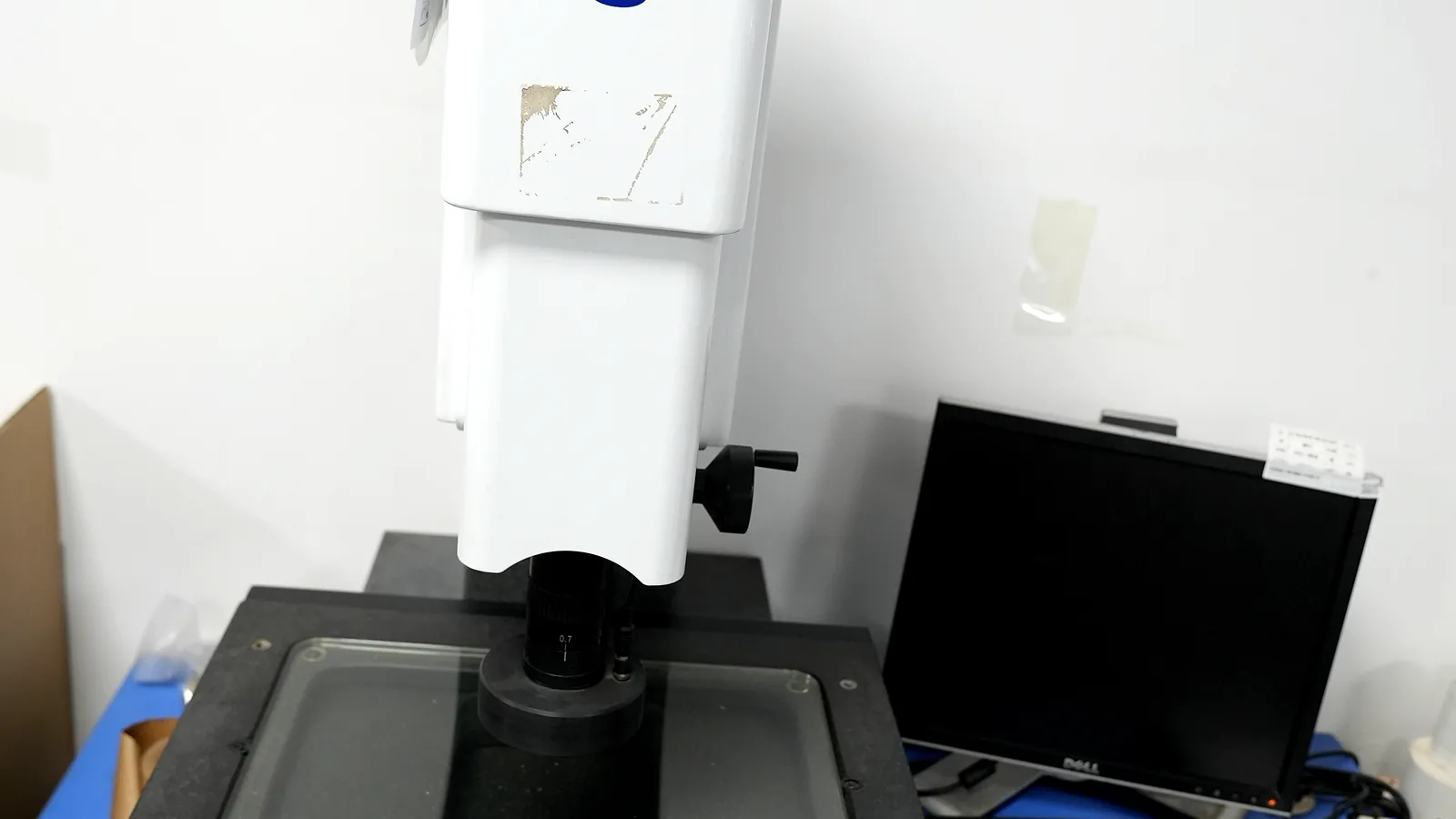
Do not approve outline, hole positions, LED windows, or mounting cut-outs on a flat desk only. Dry-fit the sample on the actual housing or a fixture that matches the mounting surface. Shared datums from ASME Y14.5 language—primary plane plus two secondary features—keep supplier VMS or optical measurements comparable to the OEM CMM.
The drawing must separate overall outline, critical cut-outs, print-to-cut registration, key centers, windows, tail exit, and total thickness because they may use different processes and inspection methods. Multi-point optical measurement is usually more informative for X-Y position than a single calliper reading. Callipers and micrometers still help with thickness and accessible linear features; they do not replace positional measurements from the agreed datum frame.
| Feature | Acceptance basis | Suitable evidence | Approval record |
|---|---|---|---|
| Overall outline | Released profile tolerance | Optical comparator or VMS | Actual values and deviation |
| Critical cut-outs and windows | Position from shared datums | VMS, pin gauges, or dedicated fixture | Feature-by-feature result |
| Print-to-cut registration | Artwork-to-cut requirement | Optical overlay or vision measurement | Registration result by critical area |
| Stack thickness | Drawing nominal and tolerance | Micrometer at defined points | Point locations and actual values |
Housing dry-fit photos + critical dimensions measured from the shared datum with method named (optical comparator, VMS-class system, pin gauges).
“Outline looks good” with no measured values and no housing present.
2.4 Tactile feel and actuation consistency (all keys)
For tactile constructions, press every key several times—not only the center keys. Measure every key. Corner keys, large keys, and keys near the tail exit can feel different because of support, actuator geometry, preload, and air path. Snaptron technical definitions distinguish trip force, release force, tactile ratio, travel, and over-travel; those variables interact with the overlay and spacer stack. A single universal gram-force number cannot approve every design.
If the RFQ named a force window, measure it on a force gauge during prototype membrane switch testing. If no number was named, freeze a reference sample both sides agree feels correct, and keep it under change control.
All keys exercised; force method or reference sample ID recorded; shorting/non-tactile designs still checked for travel and contact consistency.
Only three “hero” keys pressed once; no record of corner-key behavior.
2.5 Electrical continuity, insulation, and path baselines
Prototype membrane switch testing must include continuity of every switch path, insulation between isolated nets, and connector pin mapping. A pass sticker is not a baseline. Recording actual loop resistance per path—not only pass/fail against a single limit—creates a baseline for production drift monitoring. The IPC-TM-650 Test Methods Manual separates dimensional, mechanical, electrical, chemical, and environmental methods; the sample plan should select only the methods that match the construction and product risk.
| Electrical check | Why it belongs in FAI | Notes |
|---|---|---|
| Continuity / loop Ω per path | Detects opens, thin ink, long-path drift | Record numeric Ω, not only pass |
| Insulation / hipot class test | Catches silver bridges and moisture paths | Method and voltage on SIP |
| Pin map vs schematic | Prevents reverse tails and wrong ZIF side | Match TE Connectivity-class drawings |
| LED polarity / current (if used) | Confirms backlight circuit before assembly | At nominal V, not only diode beep |
Per-path measured values, test voltage/method for insulation, and pinout map matching the schematic.
“Electrical OK” with no data sheet; different test fixture than production will use.
2.6 Tail exit, fold path, and connector mating
The flex tail is the sample item most often missed at visual review and most painful at assembly. Confirm exit side, exit position, length, fold lines, stiffener location, and connector mating (pitch, contact side, thickness, actuator style for ZIF/LIF families such as TE Connectivity examples). Fold lines should not sit on active printed contacts. IPC-2223-class flex practice and common manufacturer tips treat minimum bend radius as thickness-dependent (illustrative rule of thumb often cited around multiplies of tail thickness—confirm on the stack).
Tail dry-routed into the real enclosure path; connector fully mated and unmated; fold shown on drawing.
Tail length “looks long enough” with the panel on a desk and the connector still in a bag.
2.7 Adhesive bond and release-liner process
Adhesive approval is not a brand name on a quote line. It is wet-out on the actual substrate—smooth aluminum, powder coat, ABS, PC+ABS, or LSE plastics. Public 3M family positioning still holds as a teaching example: 467MP-class 200MP acrylics are commonly chosen for high-surface-energy metals and plastics; 9495LE / 300LSE-class constructions are often used for many LSE plastics and powder coats. Covestro-class PC films and Autotype-class hard-coated PET overlays both appear in OEM stacks; the adhesive choice follows substrate energy more than brand preference. Surface prep (clean, dry, unified surface, firm pressure) still dominates field results per 3M bonding guidance.
Housing material named; adhesive family and thickness on the stack drawing; dry-fit edge lift checked after recommended dwell guidance from the adhesive TDS.
Generic “3M adhesive” with no series, no substrate data, and edge lift ignored.
2.8 Sealing and edge integrity when IP is claimed
If the product claims IP65, IP67, or similar, the sample gate must include the seal strategy—perimeter adhesive land width, gasket interface, tail exit sealing, and any vent path for embossed keys. IEC 60529 rates enclosures for electrical equipment. A membrane switch sample on a desk does not by itself prove the finished equipment rating.
Seal land dimensions on the drawing; sample built with production adhesive path; test plan states equipment-level method and acceptance.
“IP67 membrane switch” label with no seal land design and no equipment-level test plan.
2.9 Lighting, LED, and window performance (if designed)
Backlight windows, deadfronts, light-guide film, and discrete LEDs fail in ways desk photos hide: hot spots, color shift through translucent inks, window mis-registration to LED positions, and light bleed under emboss. Check at operating voltage and viewing angles used in the product.
Lighting checked at nominal voltage; window-to-LED registration measured; deadfront readability verified in dark and ambient conditions.
LEDs never powered during sample review; windows approved from print-side only.
2.10 Documentation: revision freeze, FAI data, written release
A membrane switch first article package should record measured dimensions, electrical data, materials or lots required by the SIP, adhesion checks when specified, and a clear verdict. The scope matters. ISO 2409:2020 describes a cross-cut test for paints and varnishes. ASTM D3359-23 is limited to coating adhesion on metallic substrates, while ASTM F2252/F2252M-25 addresses ink or coating adhesion on flexible packaging materials and explicitly leaves acceptance criteria to the user and producer. None creates one universal pass grade for every membrane-switch ink and film. Written release should state the approved revision, open deviations, and whether approval is full or conditional.
Signed approval note or controlled form citing drawing rev, sample IDs, measured data, and production authorization language.
Chat message “looks good, go ahead” with no attachment trail.
Multi-domain sample approval checklist matrix
| Domain | Minimum checks | Record |
|---|---|---|
| Appearance | Real-light legends, texture, deadfront, scratches/bubbles | Photo set + color method |
| Fit | Outline, holes, windows, housing dry-fit, thickness if critical | Measured values vs drawing |
| Feel | All keys, return, corner keys, force if specified | Force data or reference sample ID |
| Electrical | Continuity, insulation, pin map, per-path resistance if required | Numeric table |
| Tail / connector | Exit, length, fold, mating cycles | Assembly photo + pin check |
| Adhesive | Substrate match, edge wet-out, liner type | Stack + substrate note |
| Sealing (if claimed) | Land width, exit seal, equipment test plan | Drawing + test plan ID |
| Lighting (if designed) | Voltage, registration, bleed, deadfront | Photo/video at voltage |
| Documentation | Rev match, SIP/FAI, written verdict | Controlled approval record |
3. Step-by-Step Buyer Process From RFQ to Written Release
This sequence turns the framework into actions procurement and engineering can run together.
Step 1 — Freeze the sample class and acceptance criteria in the RFQ
State whether the purchase is a legend mockup, a functional prototype, a production intent membrane switch sample, or a formal first-article lot. Attach the drawing package, stack-up, environmental targets, connector part number, and the inspection list that will be used at approval. Ask the supplier’s prototyping capability team to confirm which process path the sample will use.
Step 2 — Align drawings and datums before any sample ships
Require one shared datum reference frame on enclosure and switch drawings (ASME Y14.5 / ISO 1101 language). Resolve open choices—tactile vs non-tactile, adhesive family, LED positions, tail exit—before calling the sample “production-intent.” Open choices produce samples that cannot be compared across suppliers.
Step 3 — Build and label the sample under change control
Every unit should carry a revision mark that matches the packing list and inspection report. If temporary tooling is used, label that fact. Production-intent claims require production materials and the intended lamination sequence, even when the die is still temporary.
Step 4 — Run prototype membrane switch testing by domain
Execute the matrix in §2: appearance, housing fit, feel, electrical, tail/connector, adhesive, sealing, lighting. Use the supplier’s quality testing methods where they match the SIP, and repeat critical checks on the OEM side when the risk justifies it. Prefer numeric baselines over binary stickers.
Step 5 — Hold a multi-discipline review before anyone says “approved”
Mechanical owns fit and stack. Electrical owns pinout and resistance. Industrial design owns color and legends. Quality owns the written record. One signature is not enough. One discipline signing alone is a common failure mode—especially when purchasing is pressured to release material POs.
Step 6 — Issue full or conditional written release
Full release freezes the revision for production. Conditional release lists the exact open actions (for example, “tail exit +0.5 mm on next lot; color OK”). Do not treat conditional items as folklore in email threads. If the remaining risk affects tooling geometry, stop production release.
Step 7 — Carry the FAI baseline into production monitoring
Keep the approved sample and the numeric report under retention rules that match the product’s quality system. Production lots should be compared to the baseline, not only to loose drawing limits, so drift is visible before field failures.
Text process flow (approval path)
RFQ + acceptance criteria
Shared datum / drawing freeze
Production-intent sample build (labeled rev)
Domain tests: appearance · fit · feel · electrical · tail · adhesive · seal · light
Multi-discipline review
Written full / conditional release → production monitoring vs FAI baseline
Failure chain if one domain is skipped
Skip housing dry-fit → outline “OK” on desk → production die cut → panel buckles in pocket
Skip per-path electrical → pass/fail only → ink thickness drifts → intermittent field opens
Skip adhesive substrate data → sample on glass plate → lift on powder coat after heat
Skip written rev freeze → “approved” chat → production prints older artwork
4. Release Blockers That Disqualify a Sample From Production Release
These override good cosmetics elsewhere in the package.
- Sample class is undefined — mockup language used to authorize production materials.
- Drawing revision mismatch — sample, report, and PO cite different revs.
- No housing dry-fit — outline and holes approved on a table only.
- Incomplete key exercise — corner keys or keys near the tail never pressed.
- Electrical “OK” without data — no continuity map, no insulation method, no baselines when the drawing requires them.
- Connector not mated — tail length and contact side never proven in the real connector family.
- Adhesive name without substrate — especially on LSE plastics or powder coat.
- IP claim without seal design or equipment test plan — marketing language on a loose sample.
- LEDs never powered on a backlit design.
- Approval only in chat — no controlled written verdict or retained sample ID.
- Supplier refuses measured FAI values when the contract called for a membrane switch first article.
- Open deviations treated as “fix later in mass production” without a controlled change and re-sample when the deviation touches tooling geometry.
5. Engineering References and How to Use Them
These sources define methods and boundaries; the released drawing and project inspection plan remain controlling.
- SAE AS9102C, First Article Inspection Requirements — useful for recorded first-article logic, not a blanket requirement for every membrane switch.
- AIAG PPAP, Production Part Approval Process — production-part approval context for automotive supply chains.
- ASME Y14.5, Dimensioning and Tolerancing and ISO 1101:2017 — datum and geometric-tolerance language.
- IEC 60529 — enclosure ingress-protection classification and the boundary of an IP claim.
- ISO/CIE 11664-6:2022 — CIEDE2000 color-difference calculation.
- IPC-TM-650 Test Methods Manual — method families for printed-circuit materials and structures.
- ISO 2409:2020, ASTM D3359-23, and ASTM F2252/F2252M-25 — coating or ink adhesion methods with different material scopes.
- IEC 60068-2-14:2023 and IEC 60068-2-78:2025 — change-of-temperature and damp-heat test methods when the product plan requires environmental evidence.
6. Frequently Asked Questions
What is membrane switch prototype approval?
Membrane switch prototype approval is the documented decision that a defined sample class—usually a production intent membrane switch sample or first-article lot—meets the drawing and inspection package across appearance, fit, feel, electrical, sealing intent, lighting if designed, and documentation. It is not a casual photo review of a legend mockup.
What is a production intent membrane switch sample?
A production intent membrane switch sample is built with the materials, stack sequence, adhesives, domes, and process path intended for volume, inspected against the same criteria production will use. Temporary tooling may still be in play, but the construction should not be a one-off lab stack that production cannot repeat.
How does a membrane switch first article differ from a quick prototype?
A membrane switch first article emphasizes recorded measurements and process freeze: critical dimensions, electrical values, structure vs drawing, and a formal pass/fail against the SIP. A quick prototype may only prove that a circuit concept works. First-article principles follow the same logic as industrial FAI practice (including AS9102-style form thinking) without requiring any specific aerospace certification claim.
What should prototype membrane switch testing include at minimum?
At minimum: real-light appearance, housing dry-fit of outline/holes/windows, all-key feel, continuity and insulation with pin map, tail routing and connector mating, and adhesive edge behavior on the real substrate. Add seal testing and lighting checks when the design claims them. Prefer numeric records over verbal "OK."
Can a print-only overlay approve a full membrane switch?
No. A print-only overlay can approve legends and rough outline for industrial design. It cannot approve dome feel, circuit resistance, rear adhesive wet-out, or connectorized tails. Using it as production authorization is a process error.
Which adhesion tests are commonly referenced for printed overlays?
ISO 2409 and ASTM D3359 describe cross-cut / tape methods widely used to grade coating and ink adhesion. Pass criteria are project-specific for ink, primer, and film (PET vs PC). Name the method and grade on the SIP; do not invent a universal industry grade.
Does an approved sample prove IP67 by itself?
No. IEC 60529 rates enclosures for electrical equipment. Sample approval can verify that the switch construction matches the seal design (land width, adhesive path, tail exit). Equipment-level testing still belongs to the finished product plan.
When should production wait after sample review?
Wait when fit fails on the housing, tail direction or length is wrong, key feel is unstable, color is disputed without a method, adhesive lifts on the real substrate, electrical data is missing, or documentation revisions do not match. Conditional approval is valid only when remaining actions cannot corrupt frozen tooling geometry.
Who should sign membrane switch prototype approval?
At least mechanical (fit/stack), electrical (circuit/connector), and quality (record/release). Industrial design should sign when color and legend are critical. Purchasing can release POs only after the technical verdict is written.
7. What to Do Next
Treat membrane switch prototype approval as a multi-domain gate, not a single photo. Name the sample class, dry-fit the housing, test every key and every circuit path, prove the tail and adhesive on real materials, and freeze a written revision before production. When lighting or IP claims exist, include those domains explicitly.
For a production-intent sample review, send the enclosure CAD or STEP file, switch drawing revision, PET or PC stack-up, connector part number, and the inspection plan used for release. JASPER Engineering can then identify which checks belong in the first sample, which require the assembled enclosure, and which should remain open until production tooling. Plan the review around measured evidence, not optimism.
Approve measured evidence, not appearance alone
Send the drawing revision, enclosure CAD, stack, connector, and acceptance plan. JASPER Engineering will identify what the first sample must prove before production release.