
Embossed graphic overlay design is a drawing-and-validation problem, not a styling checkbox. For OEM mechanical, HMI, quality, and sourcing teams, this guide decides how to define raised geometry, datums, print–form–cut registration, film construction, window clearance, key support, tooling release, and first-article evidence. It does not provide a universal height, radius, material, or tolerance: those limits depend on the named film grade, coating, ink stack, tool, process, adhesive, actuator, housing, and inspection method. The safe release is a formed-state drawing plus a production-intent sample measured in the intended assembly.
JASPER certifications: ISO 9001, ISO 13485, IATF 16949, and ISO 14001.
A raised key can look centered on a flat proof and still miss the actuator after printing, forming, adhesive conversion, die cutting, and installation. Start with the finished coordinate chain, then choose the emboss type and process around it. Teams that need a converted part can review JASPER's custom graphic overlay scope without turning this guide into a product pitch.
1. Why This Decision Matters
An emboss changes more than the visible surface. It changes the film's local shape, the location of printed borders and legends after forming, the adhesive pattern below the key, the relationship to a dome or mechanical actuator, and the way the part sits in the enclosure. A drawing that says only “pillow emboss” leaves every one of those relationships open.
Current converter terminology is fairly consistent: a pillow emboss raises the full key zone, while rim embossing raises a perimeter and leaves the center substantially flat. Dome, rail, locator-bump, and decorative forms add other profiles. Telamco and Interlink Electronics use these terms for their own offerings. The names are useful shorthand; they are not dimensioned geometry.
The functional stack is the real design object:
Operator finger
↓
hardcoat and printed film
↓
formed emboss profile
↓
adhesive opening or relief
↓
actuator or metal/polyester dome
↓
spacer and circuit
↓
rigid support, PCB, backer, and housing
A raised film surface does not automatically create snap action. The installed film, adhesive, dome or actuator, spacer, circuit, and support determine the force–displacement result. JASPER's testing and validation guidance makes the same boundary explicit: fit, graphics, key response, mounting, and system validation need named conditions rather than a generic “full test” request.
The failure chain to break before tooling
| Open input | What can happen during conversion | What the assembled panel may show | Evidence that closes the risk |
|---|---|---|---|
| No common product datum | Artwork, emboss, cut, and housing use different origins | A centered icon sits off the switch or window | One datum map and a print–emboss–cut coordinate report |
| Height callout without a section profile | Toolmaker supplies unspecified top land, transition, radius, or wall | Whitening, local thinning, poor return, or a different finger feel | Formed cross-section and agreed profile measurement |
| Material called out only as “PET” or “PC” | Grade, gauge, hardcoat, finish, and primer vary | Springback, ink damage, surface mismatch, or repeat-order drift | Exact supplier grade, lot identity, gauge, finish, primer, and direction |
| Adhesive carried through the moving key zone | Local stack stiffness and preload change | Higher effort, slow return, or inconsistent keys | Adhesive relief drawing plus mounted key evaluation |
| Flat artwork proof treated as part approval | Print looks correct before forming but shifts around a window or key | Border error, legend distortion, haze, or light leakage | Formed, cut, mounted sample reviewed lit and unlit |
Tooling makes these omissions expensive because a correction may touch the die, artwork, cutting program, adhesive pattern, fixture, and inspection plan at once. The useful question is therefore not “Which emboss looks best?” It is “What controlled evidence proves that this formed feature belongs at this location, in this stack, under these operating conditions?” The nine-point framework below answers that release question.
2. The Nine-Point Embossed Graphic Overlay Design Framework
The nine criteria follow the order in which uncertainty should be removed: purpose and type; formed geometry; datums and registration; exact material; grain and print; windows and lighting; adhesive and support; tooling control; then validation. A downstream test cannot repair an undefined upstream drawing.
2.1 Choose the emboss type from its functional job
First write what the raised feature must do. “Make it tactile” is incomplete: the part may need to locate a key by touch, preserve a printed center, clear an actuator, identify a zone, form a snap feature, or add decoration. Those jobs lead to different profiles.
| Construction | What is raised | Good fit | Weak fit or boundary | Required drawing view |
|---|---|---|---|---|
| Flat overlay | Nothing | Dense key fields, critical windows, low stack disturbance, no raised cue needed | Poor choice only when a physical location cue is a validated user requirement | Plan view and stack section |
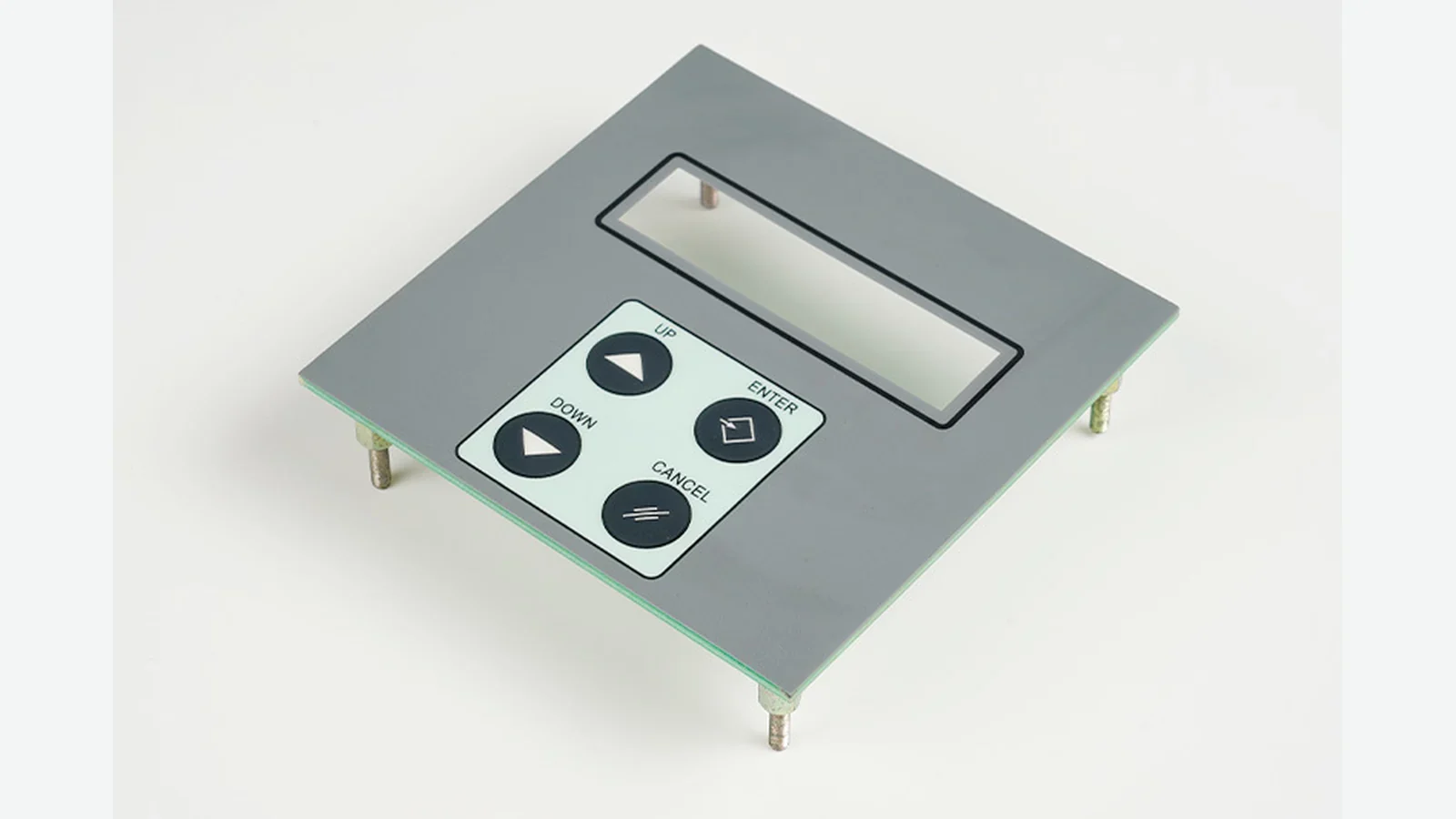
| Pillow emboss graphic overlay | Most or all of the key target | Broad finger target; visible raised key zone | Not automatically a snap element; can disturb a large printed or backlit area | Plan plus two orthogonal sections for non-circular keys |
| Rim embossing | Perimeter around a substantially flat center | Keeps a legend, icon, or LED center flatter while marking the boundary | Weak where the narrow rail approaches a window, cut, or another formed feature | Rail centerline, width, height, radii, and corner sections |
| Dome emboss | Rounded formed center | Project specifically needs the film itself to carry a dome-like profile | Must not be confused with a metal dome below the overlay | Radial section and assembled stack |
| Locator bump or rail | Small local feature | Orientation cue, zone boundary, or finger guide | Does not prove switch actuation or accessibility compliance | Local section and position from product datums |
| Decorative emboss | Logo, border, or non-switch form | Appearance is the documented purpose | Poor choice where forming can disturb a seal land, display, or controlled surface | Appearance master plus section limits |
When embossing is not the best choice. Keep the overlay flat when the raised cue has no validated user or packaging function, the key field is too dense for stable surrounding land, the feature crosses a critical display zone, or the project values minimum disturbance of the film and print stack over three-dimensional form. A separate keycap, silicone keypad, mechanical bezel, printed texture, or housing feature may carry the location function more cleanly.
Each emboss has one named function, one profile family, and one assembled acceptance check.
The drawing calls every raised feature “pillow,” or expects rim embossing alone to create a specified tactile snap.
2.2 Define the finished profile, not just its height
An emboss height is meaningless until the reference plane and measurement state are named. The drawing should define the surrounding flat plane, finished height, top land or crown, transition, inside and outside radii, wall or draft, and the flat recovery land before the next cut, window, graphic boundary, or emboss.
For a non-circular key, add sections through the narrow axis, long axis, and any corner that controls forming. State whether dimensions apply immediately after forming, after cutting, after conditioning, or after installation. Keep the customer's finished nominal geometry separate from the converter's private process compensation; otherwise a compensated tool dimension can accidentally become the product requirement.
The GPI trade manual includes historical geometry suggestions, while current converter guides publish conflicting multipliers, radii, rail widths, and spacing. That conflict is the reason not to copy a “maximum emboss height” from a blog. The exact film grade, gauge, hardcoat, ink stack, forming route, and tool must be reviewed together.
The supplier returns a marked section drawing and states which dimensions are product acceptance values versus tool compensation.
A tool is quoted from a top-view artwork file with no formed-state section, reference plane, radius, or surrounding land.
2.3 Put print, emboss, cut, and housing on one datum system
Registration is a chain, not one ± value. ISO 5459:2024 establishes terminology and methodology for datums and datum systems; ISO 1101:2017 separates form, orientation, and location controls. For North American drawings, ASME Y14.5-2018 (R2024) is the relevant dimensioning-and-tolerancing reference. None of these documents assigns an overlay tolerance.
Use the product's mating features to establish the coordinate master:
Housing datum features
→ finished overlay cut and locating features
→ emboss center/profile
→ printed legend or border
→ actuator, dome, LED, or display window
| Relationship | What it protects | Inspect in which state | Typical evidence |
|---|---|---|---|
| Print to emboss | Legend, border, icon, and key-center alignment | Formed part | Datum-referenced overlay image or coordinate report |
| Emboss to finish cut | Raised feature versus perimeter, holes, slots, and window cuts | Formed and cut part | Critical-dimension report from the finished part |
| Cut to housing | Fit, adhesive land, bezel clearance, and window reveal | Installed part | Fit fixture or intended enclosure |
| Emboss to actuator/dome | Force path and key centering | Installed functional stack | Section review plus functional sample |
| Emboss pattern to pattern | Spacing and orientation across a repeated key field | Finished array | Pattern-level report when function depends on the relationship |
ISO 5458:2018 is relevant when repeated features need a pattern or combined geometric specification. Apply it only where the relationship among keys is functional; do not add geometric notation for decoration.
initial registration targets — project-specific. The fifth-edition GPI manual, published in 2009, gives ±0.010 in (±0.254 mm) as its industry-practice value for emboss-to-print and emboss-to-finish-cut registration. It also says ±0.005 in (±0.127 mm) can be achieved at the expense of higher scrap, cost, and slower processing. The benchmark dataset below selects ±0.005 in only for critical relationships. Neither value is a current standard, a guaranteed result, or verified JASPER capability. The converter must replace it with project capability tied to the selected material, tool, process, feature size, inspection method, and production evidence.
RFQ benchmark dataset for supplier review
The following numbers form one coherent, deliberately demanding starting scenario for supplier discussion. They are not a released part specification, an average of all converters, or a JASPER capability sheet. The scenario starts with a 0.250 mm (0.010 in) embossable hardcoated PET, selected from the upper gauge in MacDermid Alpha Autoflex EB CPI-00025/12. Geometry comes from the dated GPI trade manual and the 2018 J.N. White membrane-switch design guide. project-specific after the actual grade, print stack, toolmaker, key stack, and inspection method are known.
| Drawing or validation field | initial benchmark entry | How to use it—and when not to |
|---|---|---|
| Reference film | 0.250 mm / 0.010 in embossable hardcoated PET | Upper gauge in the named Autoflex EB family. Do not imply JASPER stock or use it where lower actuation force, tighter forming, or another chemical/optical profile makes a thinner or different grade preferable. |
| Height feasibility screen | Total formed height ≤2.5T; with T = 0.250 mm, ≤0.625 mm from the back plane and ≤0.375 mm net rise above the original top surface | GPI defines total height as including film thickness. This is an upper feasibility envelope, not the nominal height and not a cycle-life promise. |
| Rim or rail width | ≥1.27 mm / 0.050 in | Published for 0.010 in film. Recalculate if film or liner construction changes; do not force rim embossing into a dense or optical zone merely to meet this number. |
| Minimum inside radius | ≥0.508 mm / 0.020 in | A J.N. White converter guideline and a more conservative value than the GPI rule of radius at least T for this scenario. Hardcoat and ink integrity still need a formed sample. |
| Clear spacing between embossed features | ≥2.54 mm / 0.100 in | A planning keep-out between embosses, not a universal distance to a cut, display window, seal land, or housing wall. |
| Critical print-to-emboss and emboss-to-cut registration | ±0.127 mm / ±0.005 in | An aggressive GPI-supported target that may raise scrap and cost. Use ±0.254 mm / ±0.010 in as the dated baseline comparison, then require a written capability disposition for each relationship. |
| Matched-die starting geometry | Male/female metal tool; clearance C ≈ T; male and female wall draft ≥3° | For T = 0.250 mm, the starting clearance is about 0.250 mm. The toolmaker must define whether C is per side or total and must override the value for grade-specific or multilevel forming. |
| Cosmetic screening setup | 450 mm / 18 in viewing distance; 100 foot-candles; 20 seconds; part about 45° with line of sight normal to the surface | A initial GPI-style first visual screen. It does not replace dimensional inspection, magnified defect analysis, or powered viewing of windows and backlit zones. |
This construction is not the best choice when the installed key needs a lighter force response than a 0.250 mm film can support, the layout cannot provide the stated land, a window needs a wider optical keep-out, or production evidence cannot support ±0.127 mm registration economically. In those cases, change the material, geometry, process, tolerance, or interface architecture before tooling; do not waive the conflict after the die exists.
One controlled master defines product datums, while the supplier returns a relationship-by-relationship capability response.
Artwork, emboss tool, adhesive file, and die line each use a different origin or an unreferenced page edge.
2.4 Specify the exact film construction, not “PET or PC”
Polymer family is only the first material field. The release package needs the supplier, trade name, grade, nominal gauge, tolerance basis, hardcoat, finish, print side, ink primer, optical treatment, and lot identity. A substitution that preserves “PET” but changes any of those fields can change forming, appearance, print adhesion, springback, or inspection.
The examples below show why generic polymer labels are too weak. They are not a JASPER material list.
| Named first-party example | Published construction choices | What the data can support | What it cannot support |
|---|---|---|---|
| MacDermid Alpha Autotex CPI-00033/8 | Hardcoated PET; Touch, Fine, and Velvet finishes; 150, 200, and 280 µm options; primer variants for different print systems | A real PET grade family has multiple gauges, textures, and primers | A universal PET emboss height, JASPER availability, or finished-panel life |
| MacDermid Alpha Autoflex EB CPI-00025/12 | Embossable hardcoated PET; 130, 180, and 250 µm options; primer choices | “Embossable” can be a grade-level property rather than a polymer-level assumption | Suitability for the proposed radius, ink stack, tool, or actuator |
| MacDermid Alpha Autoflex PC CPI-00022/10 | Hardcoated PC; 180, 250, 380, and 480 µm options | PC grades can occupy a different gauge and optical/rigidity range | A generic claim that PC is always easier, stronger, or longer-lived |
| Covestro Makrofol portfolio | Printable and formable polycarbonate grades for specific 2D/3D uses | The exact grade and forming route belong in the selection | Interchangeability with another PC film or a finished-overlay rating |
Material certificates and supplier data answer incoming-material questions. They do not qualify the converted part. ISO 527-3:2018 defines tensile-test conditions for plastic films and sheets under 1 mm within its scope. ASTM D1204-25 measures linear dimensional change of nonrigid thermoplastic film under specified elevated-temperature conditions and can indicate lot-to-lot uniformity. Neither method predicts final print-to-emboss registration on its own.
Define the real exposures before selection: operating and storage temperature, humidity, UV, cleaners, oils, abrasion, actuation, viewing condition, and expected support stack. Then ask the converter which exact grade and process evidence addresses each one.
The quotation and first-article record name the same grade, gauge, hardcoat, finish, primer, material direction, and revision.
The supplier reserves the right to substitute any “equivalent PET” or “equivalent PC” without a new formed-part review.
2.5 Control grain direction and inspect graphics after forming
Some finishes are directional. On roll-format Autotex Steel, the visible grain runs in the machine direction, parallel to roll length. If appearance, forming behavior, nesting, or repeat-order consistency depends on direction, place an MD/grain arrow on the mechanical master and record it on the first-article report.
The print file also needs functional layers, not one flattened image. Separate at least:
- visible artwork, legends, and color references;
- white, blocker, dead-front, or translucent zones when used;
- clear, tinted, or treated windows;
- emboss outlines and section identifiers;
- finish cut, holes, slots, and datum targets;
- adhesive coverage and keep-outs;
- material direction and viewing side.
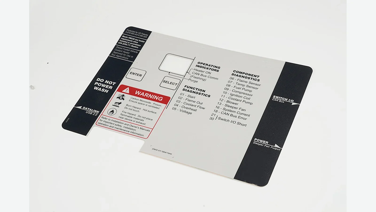
JASPER's graphic-overlay printing guidance treats color, opacity, windows, embossing, adhesive, cutting, and assembly as a connected converted-part review. That is the correct boundary. A flat PDF can approve spelling and nominal artwork; it cannot approve post-form border width, legend distortion, ink integrity, or a lit window.
Flat artwork approval and formed-part approval are separate records tied to the same drawing revision.
The supplier asks for a JPEG, rebuilds the die line independently, or cannot identify the print side and material direction.
2.6 Protect windows, dead-front graphics, and light zones
An optical area may be clear base film, a selectively treated textured surface, a printed tint, a dead-front stack, or a physical cutout. Those constructions are not interchangeable. MacDermid Alpha's a screen-printable first-surface window treatment for selected areas of textured Autotex film; that named system alone shows why “clear window” is not a complete callout.
For every window or light zone, define the active aperture, border, tint or transmission target, finish, viewing side, lit and unlit state, ambient condition, display or LED location, adhesive clearance, surface protection, and allowed cosmetic region. On an embossed control panel overlay, add the formed profile and its distance from the controlled optical boundary. Do not invent a universal keep-out: require the converter to propose one for the exact film, ink, window treatment, tool, and geometry, then inspect the production-intent part in the intended bezel and optical stack.
If the emboss crosses a critical display border or produces unacceptable thinning, haze, border movement, or light leakage, the recommended construction is not a deeper or tighter emboss. Keep the window neighborhood flat, move the raised cue, add a separate housing feature, or revise the interface. A related graphic-overlay display-window case study provides application context; it does not replace project validation.
The approval sample is reviewed in the real or representative display stack, both powered and unpowered.
A supplier approves a window by holding the loose overlay up to room light, with no bezel, display, adhesive, or formed feature present.
2.7 Design the adhesive relief and mechanical support together
Adhesive is a shaped layer in the key stack, not a generic “adhesive backing” callout. Define coverage, openings, vents if applicable, liner, edge lands, window clearance, and the housing surface it must bond to. Liner thickness affects emboss-width guidance when it is not zoned away from the formed area. Treat that as a warning to model the real stack, not as a universal command to remove all adhesive below every emboss.
3M 467MP is a useful named example: its September 2024 technical data sheet positions it for graphic attachment and overlay bonding to metals and high-surface-energy plastics, calls for clean and dry surfaces, and labels published data as representative rather than specification values. It is not a default adhesive for JASPER or for low-surface-energy, textured, coated, curved, contaminated, or flexible housings. Review the actual enclosure and service exposure. JASPER's separate membrane-switch adhesive selection guide covers that broader decision.
Support matters just as much. Record the actuator or dome center, support opening, backer/PCB flatness, bezel compression, adhesive relief, and intended travel path. Evaluate feel and return in the installed or mechanically representative stack. A loose overlay on a bench proves appearance; it does not prove actuation.
The adhesive file, actuator map, support drawing, and overlay datums share one revision and are evaluated together.
The supplier tests finger feel on an unsupported loose part or selects adhesive without the housing resin, coating, texture, and cleaning process.
2.8 Approve the tool as a controlled production asset
Do not specify a tool type from habit. The GPI manual describes matched male/female dies and die/counter-die arrangements; other forming routes can suit multilevel or deeper shapes. The converter should choose the route against the exact geometry, material, print stack, quantity, and evidence requirement, then disclose the production boundary that the customer must approve.
A useful tool-release record contains:
- tool ID, revision, date, and linked product drawing;
- tool concept or section drawing, including product nominal versus process compensation;
- selected film grade, gauge, finish, primer, print stack, and direction;
- forming route and the features or cavities covered by the tool;
- sheet/cavity map and orientation marks for first-article samples;
- inspection fixture, equipment, software, and measurement state;
- approved deviations, rework limits, and required reinspection;
- ownership, custody, storage, maintenance, repair, and change-authorization terms.
Tool approval is not a certification and does not prove unlimited process capability. The converter should confirm the press, die, process window, tool life, and registration capability for the selected construction in the project review.
The first-off report names the tool revision and maps measured parts back to sheet or cavity position.
“Tool approved” appears in email with no drawing revision, sample identity, measurements, deviations, or change-control terms.
2.9 Validate the converted part in the state that matters
Match each measurement to the characteristic. ISO 4593:1993 covers mechanical scanning of plastic film thickness and explicitly says the method is not suitable for embossed film or sheeting. ISO 4591:1992 provides a gravimetric average-thickness route with particular value for embossed sheeting, but it still does not measure local emboss height, radius, wall, or position. A profile requirement therefore needs a separately agreed instrument, fixture, sampling plan, and data-reduction rule.
| Check | Production-intent sample state | Method boundary | Acceptance basis |
|---|---|---|---|
| Emboss height and profile | Named material, print stack, direction, production tool | Agreed optical, contact, section, or fixture method; state support and reference plane | Controlled drawing and measurement uncertainty |
| Print-to-emboss registration | Formed part | Common product datums; inspect legends, borders, and key centers | Relationship-specific tolerance, not one blanket value |
| Emboss-to-cut and cut-to-housing | Formed, cut, and installed states | Coordinate report plus fit fixture or intended enclosure | Drawing and approved reveal/clearance |
| Surface and print integrity | Formed part, viewed under agreed conditions | Inspect cracks, whitening, hardcoat or ink fracture, and objectionable thinning | Approved appearance master and defect rules |
| Window and light zone | Mounted over the intended or representative optical stack | Powered/unpowered states, defined ambient light and viewing position | Aperture, haze/clarity, border, tint, leakage, and readability requirements |
| Key force and return | Complete supported key stack | Agreed force–displacement method and actuator geometry | Project curve, limits, and subjective reference where needed |
| Contact cycling | Complete membrane-switch assembly only | ASTM F1578-24 setup to a project-defined count, optionally under stated electrical load | Electrical, mechanical, and visual criteria before/during/after cycling |
| Adhesive bond and edge condition | Actual housing material, finish, cleaning, and installation process | Project peel/shear/conditioning method as applicable | No unacceptable lift, bubble, slip, or functional interference |
| Environmental exposure | Final representative stack | Only conditions tied to the use case | Predefined post-exposure geometry, appearance, adhesive, optical, and functional checks |
For the user-authorized project-specific dataset, 1,000,000 actuations may be entered as a initial design-validation target only for a complete, production-intent switch assembly. ASTM F1578-24 supplies the cycling method but does not prescribe that count; the count is a mid-to-upper planning value anchored to J.N. White's published polyester benchmark. Record electrical, force/return, and visual results before, during, and after cycling. Replace the count with the real mission profile. It is not a JASPER life claim and says nothing about a loose graphic overlay by itself.
ASTM lists F2592-16, the former membrane-switch force–displacement method, as withdrawn in 2023. It must not appear on a new test plan as a current requirement. Define the force–displacement method contractually or use the customer's applicable current procedure.
Environmental methods also need a service requirement and acceptance rule. IEC 60068-2-14:2023 addresses change of temperature; IEC 60068-2-78:2025 addresses steady-state damp heat without condensation; ISO 4892-3:2024 covers fluorescent-UV exposure of plastic specimens. None assigns a universal severity, duration, or pass/fail limit for an overlay. Use them only when the finished product's operating conditions justify them.
Every test row states the sample state, condition, method, quantity, acceptance criterion, data owner, and disposition route.
A certificate says “passed environmental testing” but omits the specimen stack, severity, duration, orientation, observations, and post-test limits.
3. A Six-Step Drawing-to-Tooling Process
This sequence turns the nine criteria into controlled decisions. The order matters: product coordinates come before artwork compensation; material and process feasibility come before tool release; a physical formed sample comes before production approval.
Step 1 — Freeze the product coordinate master
Start from the intended assembly, not the page border of an illustration. Select datum features that the finished overlay and inspection fixture can reproduce: housing edges, locating holes, a display opening, or another stable mating feature. Then place cut geometry, windows, emboss centers/profiles, printed borders, actuators, domes, LEDs, and adhesive lands in that system.
Name which file controls if a PDF, DXF, AI file, and STEP model disagree. A practical hierarchy is the released mechanical drawing for product geometry, a linked vector file for appearance, and the assembly model for mating context. The project may choose another hierarchy, but it must be explicit.
Step 2 — Build one review package with all dependent layers
The package should let a converter find contradictions before a tool exists. A clean embossed control panel overlay input set contains the following items.
| Input | Minimum content | Release question it answers |
|---|---|---|
| Part identity | Part number, revision, date, units, scale, owner | Is every file describing the same product state? |
| Datum map | Primary/secondary/tertiary references and inspection targets | Where do location and orientation originate? |
| Flat plan | Outline, cuts, windows, key centers, adhesive zones | What is converted in the flat state? |
| Formed sections | Height, top land/crown, radii, transitions, flat recovery land | What finished three-dimensional shape is acceptable? |
| Film definition | Supplier, trade name, grade, gauge, hardcoat, finish, primer, viewing side | Which exact material is being formed and printed? |
| Direction | Machine/transverse or visible grain arrow where applicable | How are appearance and forming orientation controlled? |
| Artwork layers | Colors, legends, blockers, translucency, dead-front, print order | What must remain visually correct after forming? |
| Optical zones | Aperture, tint, finish, border, lit/unlit states, keep-outs | How is the display or LED area approved? |
| Adhesive and liner | Product, coverage, relief, liner, housing surface/prep | How is the part mounted without disturbing the key? |
| Actuator/support stack | Dome or actuator, spacer, PCB/backer, housing, travel path | What creates and supports the functional key response? |
| Service conditions | Temperature, humidity, UV, chemicals, abrasion, cleaning, duty | Which material and validation questions are relevant? |
| Inspection plan | Characteristics, methods, sample state, quantity, acceptance owner | What evidence will release the tool and part? |
Step 3 — Require a written feasibility and capability response
Ask the converter to return the drawing, not merely acknowledge it. The response should mark feasible geometry, proposed material and process, required compensation, window and adhesive keep-outs, inspection access, and every tolerance that cannot be demonstrated as drawn.
For the initial ±0.005 in (±0.127 mm) critical-registration target—and the dated ±0.010 in (±0.254 mm) comparison baseline—require one of three dispositions: accept with supporting evidence; propose a different project value with the reason; or identify the feature relationship that needs redesign. “Standard tolerance” is not a disposition. The response should also state which process and measurement assumptions make its value valid.
Step 4 — Approve artwork and tool definition separately
Approve spelling, color references, layer intent, and flat geometry on the artwork proof. Then approve the formed profile, tool revision, process boundary, sample map, and measurement plan on a separate tool-release record. An artwork signature cannot silently release emboss geometry.
Resolve ownership and change control before fabrication: who owns the tool, who stores it, who may repair it, what triggers customer approval, and how a replacement tool is identified. These terms protect repeat orders as much as the first run.
Step 5 — Build and inspect production-intent first articles
Use the proposed production material, print stack, tool route, cut process, adhesive pattern, and support stack. Lower-fidelity samples are useful earlier, but they cannot release a construction they do not represent. JASPER's prototyping and sample-approval guidance separates appearance, fit, functional, production-intent, and pilot evidence for this reason.
Map samples to sheet or cavity position before they are separated. Retain the mapping through measurement and disposition. Averages alone can hide rotation, scale change, edge-of-sheet displacement, or a local tool feature.
| Approval item | Evidence to retain | Pass/revise decision |
|---|---|---|
| Material identity | Supplier grade, gauge, finish, primer, lot, direction | Matches the reviewed construction |
| Tool identity | Tool ID/revision and sample sheet/cavity map | Traceable to the approved tool definition |
| Emboss geometry | Height/profile data with method and reference plane | Meets the controlled formed-state drawing |
| Registration | Print–emboss–cut coordinate results | Meets each relationship-specific limit |
| Surface | Formed-area appearance under stated viewing conditions | No unapproved damage or cosmetic deviation |
| Optical zones | Mounted lit/unlit photographs and measurements as specified | Meets aperture, border, tint, leakage, and readability rules |
| Key operation | Installed force/return or functional result | Meets the project curve and user reference |
| Adhesive and fit | Actual housing or fixture result | No unacceptable lift, bubble, slip, interference, or reveal |
| Deviations | Numbered deviation list with affected characteristics | Accepted by the named owner or returned for correction |
Step 6 — Release the part, reference sample, and change rules together
The release package should include the final drawing, linked artwork, material construction, tool record, measurement report, approved deviations, installed sample result, and retained reference sample. State what remains customer system validation.
Any later change to film grade, gauge, finish, primer, ink, print sequence, forming route, tool, adhesive, cut process, inspection method, actuator, support, or housing should trigger a defined impact review. Reapproval may cover one characteristic or the full matrix; the change record must say which. That keeps a repeat order from becoming an undocumented new design.
4. Release Blockers That Should Stop Tool Release
These conditions do not prove that a converter is incapable. They prove that the present release is not controlled. Pause the tool until the missing relationship, evidence, or ownership decision is closed in writing.
- No formed-state section drawing — A top view cannot define height reference, crown/top land, transition, radius, wall, or recovery land.
- A universal geometry promise with no material and process identity — Height, radius, and spacing claims are not transferable across grade, gauge, hardcoat, print stack, tool, and forming route.
- Separate artwork and mechanical origins — Independent page edges create hidden print-to-emboss and emboss-to-cut offsets.
- Material specified only as PET, PC, polyester, or polycarbonate — The missing grade, gauge, finish, primer, and direction can change the converted result.
- No treatment of grain, windows, or lighting — A cosmetic flat proof cannot approve a directional finish or the formed appearance of a display/LED neighborhood.
- Adhesive and support omitted from the key section — Loose-part feel is not evidence of installed force, return, or fit.
- Tool approval without tool identity and measured samples — An email approval cannot tie results to a tool revision, sheet/cavity position, or inspection method.
- One tolerance applied to every relationship — Print-to-emboss, emboss-to-cut, cut-to-housing, and emboss-to-actuator fail in different ways and require separate dispositions.
- Withdrawn or irrelevant standards presented as current compliance — A method's title does not create a product requirement; current status, specimen scope, conditions, and acceptance rules must all match the project.
5. Frequently Asked Questions
What emboss height should be specified for a graphic overlay?
There is no universal emboss height. Define the functional target and finished profile, then ask the converter to validate height, radii, wall, and surrounding land against the exact film grade, gauge, hardcoat, print stack, forming route, tool, adhesive, and support. Release the value only after production-intent evidence confirms it.
What is the difference between a pillow emboss graphic overlay and rim embossing?
A pillow emboss graphic overlay raises most or all of the key target. Rim embossing raises the perimeter while leaving the center substantially flat. Pillow suits a broad raised target; rim can preserve a flatter legend or LED center. Neither term defines dimensions, and neither guarantees snap response without the complete key stack.
Is ±0.005 in or ±0.010 in a verified JASPER emboss tolerance?
No. Both values come from the GPI trade manual's fifth edition, published in 2009. It lists ±0.010 in (±0.254 mm) as the industry-practice baseline and says ±0.005 in (±0.127 mm) is achievable with higher scrap, cost, and slower processing. Use both only as supplier-review starting points. The released drawing must use a project-specific value supported by the selected material, process, and inspection method.
Should PET or polycarbonate be used for an embossed control panel overlay?
Choose an exact grade, not a polymer label. PET and PC product families contain different gauges, hardcoats, finishes, primers, optical properties, and forming claims. Compare the selected supplier data, tool/process review, formed sample, use environment, window needs, and installed key behavior. “PET” or “PC” alone cannot release the design.
How close can an emboss be to a display window or cutout?
No universal keep-out applies. Required distance depends on the film, gauge, coating, printed layers, window treatment, emboss profile, cut geometry, tool, and optical acceptance. Ask the converter to propose the keep-out, then inspect the formed and cut part in the intended bezel and display stack, powered and unpowered.
How should emboss height and profile be measured?
Name the reference plane, sample support, measurement state, instrument, fixture, locations, sampling, and uncertainty. ISO 4593:1993 is not suitable for thickness measurement on embossed film; ISO 4591:1992 provides average gravimetric thickness, not local profile. The project therefore needs a separately agreed height/profile method tied to the drawing.
Does an embossed overlay create tactile feedback without a metal dome?
It can create a raised location cue or a film-flex response, but a defined snap or force curve belongs to the complete stack. Film, adhesive relief, actuator or dome, spacer, circuit, PCB/backer, housing, and travel all matter. Evaluate the production-intent assembly with an agreed force–displacement and return method.
When is a flat overlay better than an embossed overlay?
A flat overlay is often better when no raised cue is required, keys are tightly spaced, a critical optical area would be disturbed, the support stack cannot tolerate added form, or maximum film/print continuity matters more than a raised feature. Printed texture, a housing ridge, keycap, or silicone keypad may carry the location function instead.
What should an embossed graphic overlay design drawing include?
Include part identity and revision; units; product datums; flat plan; formed sections; exact film, gauge, finish, primer, and direction; layered artwork; window and light zones; adhesive relief; actuator/support stack; service conditions; relationship-specific tolerances; tool record requirements; inspection methods; sample mapping; and approval owners.
What certifications does JASPER hold?
JASPER holds ISO 9001, ISO 13485, IATF 16949, and ISO 14001 certifications. These management-system certifications do not by themselves establish product approval or validate a project-specific material, process, test result, or end-use requirement.
6. What to Do Next
Before releasing an emboss tool, put the product datums, formed sections, exact film construction, layered artwork, window conditions, adhesive relief, actuator/support stack, and acceptance matrix into one controlled package. Ask the converter to return every open limit and process assumption on the drawing.
JASPER is one possible manufacturer for that review. Teams can review an embossed overlay drawing by providing the mechanical PDF/DXF, vector artwork, housing or STEP context, material notes, window and lighting states, adhesive/housing information, key-stack details, service conditions, and the evidence required from the first article. Other qualified converters should be judged against the same framework.
Technical References
- Source: Telamco. Accessed 2026.
- Source: Interlink Electronics. Accessed 2026.
- Source: GPI trade manual. Accessed 2026.
- Source: ISO 5459:2024. Accessed 2026.
- Source: ISO 1101:2017. Accessed 2026.
- Source: ASME Y14.5-2018 (R2024). Accessed 2026.
- Source: ISO 5458:2018. Accessed 2026.
- Source: MacDermid Alpha Autoflex EB CPI-00025/12. Accessed 2026.
- Source: J.N. White membrane-switch design guide. Accessed 2026.
- Source: MacDermid Alpha Autotex CPI-00033/8. Accessed 2026.
- Source: MacDermid Alpha Autoflex PC CPI-00022/10. Accessed 2026.
- Source: Covestro Makrofol portfolio. Accessed 2026.
- Source: ISO 527-3:2018. Accessed 2026.
- Source: ASTM D1204-25. Accessed 2026.
- Source: Autotex Steel data sheet. Accessed 2026.
- Source: 3M 467MP. Accessed 2026.
- Source: ISO 4593:1993. Accessed 2026.
- Source: ISO 4591:1992. Accessed 2026.
- Source: ASTM F1578-24. Accessed 2026.
- Source: withdrawn in 2023. Accessed 2026.
- Source: IEC 60068-2-14:2023. Accessed 2026.
- Source: IEC 60068-2-78:2025. Accessed 2026.
- Source: ISO 4892-3:2024. Accessed 2026.
Review the finished overlay construction before release
Send the drawing, artwork, substrate, adhesive, assembly, environment, optical states, and acceptance evidence for a construction-specific review.