
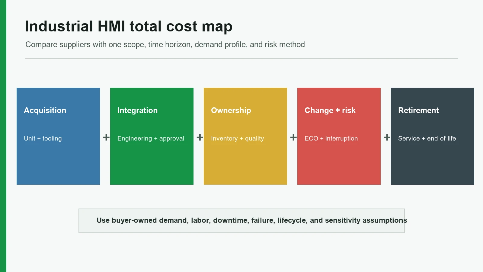
Industrial HMI panel total cost of ownership is the cost of acquiring, integrating, operating, changing, supporting, and retiring the panel—not its quoted unit price. OEM engineering and sourcing teams can use this guide to compare custom HMI assembly suppliers, provided they enter project-specific demand, labor, downtime, failure, and lifecycle assumptions.

A useful decision starts with a boundary. This guide addresses a custom operator-interface assembly that may combine a graphic front, membrane switch or touch sensor, display or window, PCB/FPC, harness, connector, carrier, gasket, mounting parts, and agreed production checks. It does not rank programmable HMI terminals or estimate a factory's downtime without its operating data.
1. How to Calculate Industrial HMI Panel Total Cost of Ownership
An industrial HMI lifecycle cost model must apply one scope, time horizon, demand profile, and risk method to every candidate. IEC 60300-3-3:2017 treats lifecycle costing as a structured economic-analysis process for managers, engineers, finance personnel, contractors, and commissioning teams—not as a quotation comparison. NIST Manufacturing Extension Partnership material likewise puts acquisition beside transport, inventory, transaction, quality, compliance, and sourcing risk.
For a custom HMI program, a practical planning equation is:
Expected HMI lifecycle cost = acquisition + integration + recurring ownership + expected change/risk + end-of-program cost − residual value
This is an editorial worksheet, not an IEC formula. It becomes meaningful only after the OEM defines each variable. For an uncertain event, a buyer may use event probability × consequence cost, then test a low, expected, and high case. A probability without field data is an assumption, so mark it as such.
| Cost bucket | Include at minimum | Evidence or input owner | Common comparison error |
|---|---|---|---|
| Acquisition | Unit price, tooling, screens/dies, fixtures, programming, samples, qualification builds, freight, duties, buyer-owned parts | Supplier quote plus buyer logistics | Comparing one supplier's assembled scope with another supplier's loose components |
| Integration | Drawing closure, enclosure changes, software/configuration, harness work, test-fixture development, installation labor, initial inspection | OEM engineering and operations | Treating internal engineering hours as free |
| Recurring ownership | Incoming inspection, line test, inventory, preventive service, repair labor, spares, supplier management, warranty handling | OEM quality, service, procurement | Applying a generic failure or downtime rate |
| Change and risk | Yield loss, escapes, rework, validation repeats, engineering changes, obsolete parts, last-time buys, expedite, line interruption | Shared; probabilities belong to OEM risk owners | Entering a dramatic risk cost with no probability range |
| End of program | Tool disposition, remaining inventory, data handoff, disposal, final service stock, source transfer | OEM program and supplier contract | Omitting shutdown because it occurs after production revenue ends |
Normalize the quotation before entering costs. A low unit price can be accurate for a narrow supply boundary. A higher quote can be accurate for an installed module with a test fixture and retained records. Neither is automatically better. The first task is to make both quotes describe the same deliverable.
Use a worksheet with separate columns for supplier evidence, OEM assumption, calculation, and confidence. That separation prevents a purchasing estimate from being mistaken for a guaranteed supplier result. It also exposes the variables worth testing. If the ranking changes when inspection labor moves by one plausible shift or the program runs six months longer, the decision is sensitive and needs stronger evidence.
TCO input ownership and evidence
| Cost input | Buyer-owned basis | Supplier evidence | Calculation boundary |
|---|---|---|---|
| Demand and order pattern | Forecast, service stock and program horizon | MOQ, pack quantity and repeat-order terms | Use the same scenarios for every candidate |
| Integration work | Internal labor rates and approval workflow | Drawing, tooling, sample and test scope | Separate one-time and recurring work |
| Quality cost | Failure consequence and internal handling cost | Yield denominator, inspection and corrective-action records | Do not convert a certificate into a failure rate |
| Change and obsolescence | Redesign labor, qualification and interruption exposure | Notice period, alternate control and lifecycle method | Calculate named change scenarios |
| End-of-program support | Service duration and final inventory policy | Tool ownership, records and last-time-buy terms | Keep residual value explicit |
2. Map the HMI Assembly Stack Before Pricing Risk
A custom HMI panel assembly is a controlled handoff, not a picture of a finished panel. JASPER's current product page defines its possible boundary as the released front, input device, display or window, PCB/FPC, interconnect, connector, carrier, gasket, mounting features, and agreed checks. The default scope excludes PLC programming, SCADA development, machine wiring, safety logic, cabinet certification, and complete-equipment validation unless the released project names them.
A sourcing team should redraw that boundary for its own project:
Operator / cleaning / sunlight / gloves
Graphic surface or cover lens
Input layer: membrane, capacitive, or silicone
Display window or supplied display + optical relationship
PCB/FPC + lighting + controller/configuration boundary
Harness + connector + pinout + grounding
Carrier + gasket + fasteners + enclosure datums
Machine electronics, software, safety functions, final validation
The cost failure chain usually starts at an interface, not at a line-item price:
Unclear owner → omitted requirement → late design change → new sample/fixture → repeated approval → schedule or inventory cost
A second chain affects repeat orders:
Generic component description → untracked part change → fit/electrical difference → containment and requalification → service-stock exposure
This stack also sets a “make versus integrate” boundary. Assigning more work to one supplier may reduce handoffs, but it can increase dependence on that supplier's documentation and continuity controls. Keeping modules separate can improve service access and dual sourcing, but the OEM then owns more tolerance, connector, software, and validation interfaces.
3. A 10-Point HMI Supplier Evaluation Framework
A useful HMI supplier evaluation reviews evidence, not adjectives. The default weights below total 100%, but they are not an industry standard. A medical laboratory device, outdoor machine, and short-life test fixture should not use the same weighting. Change the model before releasing an RFQ, then apply it consistently.
| Criterion | Default weight | Evidence to request before scoring |
|---|---|---|
| Scope and responsibility boundary | 15% | Assembly drawing, BOM, responsibility matrix, quotation inclusions/exclusions |
| Tooling and NRE definition | 10% | Itemized asset register, ownership, storage, maintenance, change terms |
| BOM and component lifecycle | 12% | Manufacturer part numbers, approved alternatives, lifecycle status, notices |
| Assembly yield and quality evidence | 12% | Control plan, acceptance limits, inspection/test records, nonconformance path |
| Validation and approval boundary | 12% | First-article plan, qualification matrix, fixtures, system-validation owner |
| Engineering changes and configuration | 10% | Baseline, effectivity, change notice, history, reapproval triggers |
| HMI panel reliability evidence | 10% | Methods, specimen state, sample count, severity, acceptance and post-checks |
| Serviceability and repair | 7% | Replaceable-unit plan, access, spares, diagnostics, field instructions |
| Documentation and traceability | 7% | Revision/lot links, approved reference, labels, record-retention terms |
| Repeat-order and continuity risk | 5% | Tool status, source controls, restart plan, forecast and inactivity assumptions |
3.1 Scope and responsibility boundary — 15%
Record ownership for the display, controller board, firmware/configuration file, gasket, fasteners, harness, mating connector, test fixture, protective film, label, and packaging. Name the machine-level functions left with the OEM. A rendered assembly can look complete while its commercial scope leaves half these items unresolved.
Four documents describe one handoff, with no conflicting owner or revision.
“Complete HMI” appears in the quote, but the display model, controller state, mating connector, fixture, and machine-validation owner are absent.
3.2 Tooling and NRE definition — 10%
Tooling and non-recurring engineering should be reviewed as assets and work products. Ask what each charge creates: printing screen, cutting die, mold, bonding fixture, electrical fixture, programming setup, inspection gauge, optical fixture, or engineering release package. Then record ownership, location, revision, useful condition, maintenance, duplicate availability, modification rules, inactivity treatment, replacement basis, and end-of-program disposition.
The cheapest initial tool is not necessarily the lowest-cost choice. A fixture that cannot reproduce enclosure compression may allow a sample to pass while the installed assembly fails. Conversely, expensive production tooling may be unnecessary for a low-volume design still likely to change. The fit between tool maturity and design maturity matters more than a generic “production tool” label.
Every NRE line has a purpose, deliverable, change/reuse rule, and owner.
A single tooling charge cannot be reconciled to identifiable assets or released files.
3.3 BOM and component lifecycle — 12%
The BOM should name manufacturer, exact part number, approved source, revision where relevant, and alternates for lifecycle-sensitive items. “Seven-inch industrial display” is not enough. Component lifecycle records make the rule concrete: cancellation or replacement status is attached to an exact order or catalog number, even when the broader family remains available.
IEC 62402:2019 covers obsolescence policy, planning, design, resolution selection, measurement, and improvement across an item's life cycle. Translate that principle into the supply agreement. Define who monitors notices, who approves substitutions, how much notice is required, what a last-time buy needs, which files or test programs must migrate, and what triggers sample or system requalification.
Lifecycle-sensitive parts have exact identities, monitored status, approved alternatives or resolution plans, and named notification owners.
The supplier may substitute a display, adhesive, LED, connector, controller, or PCB component based only on “equivalent specification.”
3.4 Assembly yield and quality evidence — 12%
Yield affects cost only when its definition is stable. First-pass yield, final yield after rework, scrap rate, and customer acceptance are different measures. Before asking for a percentage, define the process point, denominator, defect classification, rework treatment, time period, and product similarity. Otherwise, two honest suppliers can report incomparable figures.
Ask for critical characteristics, measurement methods, fixture conditions, sampling or every-part scope, acceptance limits, retained result format, nonconformance controls, and corrective-action workflow. The ISO 9001 Auditing Practices Group's external-provider guidance emphasizes defined selection criteria, monitoring, verification, and risk-based controls; an approved-provider list alone may not demonstrate effective control.
JASPER's public quality page describes incoming, in-process, final, and outgoing checkpoints covering appearance, dimensions, electrical behavior, assembly, documentation, packing, and changes. That is first-party process evidence, not a project control plan. Buyers still need the actual drawing-linked criteria.
“Tested” resolves to characteristics, limits, fixture state, frequency, records, and disposition.
“100% tested” is the full answer, with no test definition or result-retention rule.
3.5 Validation and approval boundary — 12%
Separate five evidence levels: supplier process checks, every-part production tests, first-article measurements, design/qualification tests, and finished-equipment validation. A good-looking prototype is only one reference state. It does not prove that the process is repeatable, that an enclosure seal performs after assembly, or that the machine meets safety, EMC, software, or regulatory requirements.
The approval package should state sample quantity, production-intent materials and processes, deviations, test fixtures, acceptance limits, reference hierarchy, and changes that invalidate approval. If the supplier runs IEC 60529 ingress tests or IEC 60068 environmental methods, the report must identify the assembled configuration and severity. IEC 60529 classifies enclosure protection; it does not make every panel bearing an “IP” label independently certified.
The matrix states what is checked, on which configuration, by whom, when, and what reopens approval.
One signed sample is treated as approval of future substitutions and complete-machine performance.
3.6 Engineering changes and configuration control — 10%
Configuration control keeps the approved physical sample connected to the files used for the next build. ISO 10007:2017 describes configuration-management planning, identification, change control, status accounting, and configuration audits from concept through disposal. For an HMI, the baseline may include artwork, mechanical drawing, circuit data, PCB files, BOM, software or controller configuration, inspection criteria, fixture program, approved sample, label, and packaging.
One status record identifies the active baseline and all approved deviations.
The sample, drawing, BOM, and work instruction can carry different revisions without a controlled disposition.
3.7 HMI panel reliability evidence — 10%
HMI panel reliability is conditional. It depends on materials, assembly state, mounting, temperature, humidity, vibration, cleaning chemistry, UV exposure, gloves, electrical loading, software behavior, and maintenance. A universal cycle-life or IP statement cannot replace evidence for the released configuration.
A usable test report names the test method, specimen state, sample count, preconditioning, severity, duration or cycles, powered/unpowered state, fixture, acceptance limits, failures, and post-test checks. IEC 60068-2-6:2007 addresses sinusoidal vibration; IEC 60068-2-14:2023 addresses change of temperature. Their existence does not determine the correct severity for a product. The OEM must derive severity from the equipment environment and applicable requirements.
Where electronics or harnesses are in scope, IPC-A-610J, IPC/WHMA-A-620E, or J-STD-001J may provide acceptance/process language if the contract selects them. Naming an IPC document is not evidence that a supplier follows it.
Evidence maps a named failure mechanism to the actual assembly and acceptance limit.
“Industrial grade,” “millions of operations,” or an IP code appears without a configuration-specific report and test boundary.
3.8 Serviceability and repair boundary — 7%
Serviceability changes cost after shipment. Define the field-replaceable unit: complete HMI, front overlay, input layer, display, board, harness, or connector. Review access direction, fasteners, destructive adhesive joints, gasket replacement, connector mating limits, calibration/configuration, serial or revision matching, diagnostics, repair skill, contamination controls, and spare packaging.
An integrated assembly is useful when registration, sealing, optics, or tested handoff outweigh field modularity. It is a poor choice when a short-life display is permanently bonded to a long-life bezel without a service rationale. The supplier should not decide this tradeoff alone; service engineering and the OEM's warranty team own consequence data.
A repair instruction identifies replaceable units, tools, consumables, acceptance checks, and compatible revisions.
Replacing one expected-wear item destroys the front module, but the TCO worksheet assumes component-level repair.
3.9 Documentation and traceability — 7%
Documentation turns a sample into a repeatable order. At minimum, connect the shipment to the active drawing and BOM revisions, approved sample or color reference, material/source requirements, inspection records, labels, packaging, deviations, and change history. Define the traceability granularity and record-retention period from project risk and contractual needs; do not assume “full traceability” means the same thing to both parties.
The public JASPER HMI page asks buyers to release assembly drawings, BOM and responsibility, interfaces, fixtures, labels, packaging, traceability, and change-control expectations together. That is a sensible RFQ structure. The project still needs to state which records accompany each shipment and which remain retrievable on request.
A sample shipment record can be traced to the exact configuration and acceptance evidence used for release.
The supplier can identify a purchase order but not the active material, artwork, circuit, fixture, or approved-reference revisions.
3.10 Repeat-order and continuity risk — 5%
Repeat-order risk grows when production pauses, demand changes, components age, or tools move. Agree how long tools and fixtures remain stored, how condition is checked, what inactivity triggers a restart review, which materials have shelf-life controls, how forecasts affect source commitments, and when a repeat order requires a new first article.
No supplier can guarantee unchanged price or availability indefinitely. A stronger contract identifies assumptions: annual volume band, order pattern, buyer-supplied inventory, approved-source status, currency/freight treatment, tool maintenance, and notice periods. IEC 62402 lifecycle planning and ISO 10007 configuration control give the buyer a framework for this discussion without promising that obsolescence can be eliminated.^5
| Repeat-order trigger | Evidence to reopen | Release decision |
|---|---|---|
| Component notice or source change | Exact part status, proposed alternate, inventory, interface delta, verification plan | Buy, qualify an alternate, redesign, or decline the change |
| Long inactive period | Tool/fixture condition, material shelf-life status, active baseline, first-piece evidence | Resume directly or require a new first article |
| Demand outside quoted band | Capacity and material assumptions, fixture cycle, inspection plan, packaging | Reprice or revise the production route before accepting orders |
| Drawing/BOM/configuration update | Effectivity, old-stock disposition, revised tests, sample need | Approve one controlled change package |
| Production-site or critical-process move | Process comparison, equipment/fixture status, source and validation effects | Audit, requalify, or retain the approved route |
This trigger table does not assign automatic outcomes. It ensures that a repeat purchase order reopens the assumptions that actually changed.
The repeat-order plan includes source monitoring, baseline verification, fixture checks, and restart evidence.
“Same as last time” is the only control after a long production gap or component notice.
4. Run a Six-Step Sourcing and Approval Process
The framework becomes useful when engineering, quality, service, and sourcing follow one sequence. Do not ask procurement to normalize technical assumptions after quotations arrive.
Step 1 — Release a boundary pack
Step 2 — Issue a normalized RFQ and TCO worksheet
Require every supplier to price the same production states and separate unit cost, each NRE item, samples, qualification support, fixtures, buyer-supplied parts, packaging, freight terms, and optional work. Put the OEM's time horizon, annual scenarios, order pattern, service strategy, labor assumptions, and risk ranges in a separate worksheet. Suppliers should provide evidence and commercial terms; the OEM should own factory downtime and field-consequence values.
Step 3 — Review evidence before scoring
Evaluate drawings, control-plan examples, change process, component lifecycle method, sample records, and test-report structure before entering scores. When a standard matters, request the document, scope, revision, certificate or report owner, and applicability to the offered configuration. UL Product iQ can verify specific UL product/component records, but a company name in a database does not establish that every offered HMI is certified.
JASPER holds ISO 9001, ISO 13485, IATF 16949, and ISO 14001 certifications. When certificate scope or site applicability is material to supplier approval, request the current certificate copies from JASPER sales and match them to the offered manufacturing site and process.
Step 4 — Approve a production-intent sample package
Approve the assembly, not only the front appearance. Record dimensions, input behavior, display and lighting states, connector output, mounting fit, cosmetic references, deviations, label, packaging, and traceability. Identify the production-intent materials and processes. If a prototype uses a temporary tool, substitute display, hand operation, or different adhesive, state how the production route will be rechecked.
Use an engineering review to close drawing, sample, interface, and validation assumptions before supplier scoring.
Step 5 — Calculate scenarios and run sensitivity checks
Calculate low, expected, and high demand cases. Vary only documented uncertainties: program length, order frequency, inspection effort, service-unit strategy, component notice, requalification event, and interruption consequence. Do not insert a supplier's marketing adjective as a probability. If a candidate wins only under one aggressive assumption, document the condition rather than presenting the ranking as stable.
Step 6 — Freeze the production and repeat-order baseline
After selection, release the approved drawing/BOM set, deviations, sample reference, inspection/test criteria, fixture/program revision, labeling, packaging, notification rules, and reapproval triggers. Record effectivity for every later change. Before a repeat build, verify component status, tool/fixture condition, source changes, open deviations, and whether the order still fits the original volume and service assumptions.
5. Use a Sample-Approval and Validation Matrix
A matrix prevents test names from masking responsibility. Customize it to the project's actual failure modes and regulatory context.
| Evidence layer | Typical examples | Frequency | Primary owner | What it does not establish |
|---|---|---|---|---|
| Incoming / in-process control | Material identity, print registration, circuit condition, connector/tool setup, lamination alignment | Per lot or defined sampling | Supplier | Finished assembly performance |
| Every-part production check | Continuity, key/touch response, LED/display state, pinout, visual criteria | Each part where specified | Supplier | Environmental life or machine safety |
| First-article evidence | Critical dimensions, BOM/source identity, assembled fit, interface outputs, appearance | Initial or triggered by change | Supplier with OEM approval | Long-term process capability by itself |
| Design / qualification test | IEC 60529 configuration test, IEC 60068 vibration/temperature method, chemical exposure, endurance plan | Defined sample set at qualification or requalification | Assigned laboratory / supplier / OEM | Performance outside tested configuration and severity |
| Finished-equipment validation | EMC, safety functions, software, field wiring, enclosure, misuse, regulatory requirements | Equipment validation plan | OEM / system integrator | Supplier process control for later lots |
For a sealed operator front, the OEM may also consult the waterproof membrane switch design resource when defining compression, tail exit, venting, and enclosure interfaces. The finished equipment still needs its own applicable verification.
6. When an Integrated HMI Assembly Is Not the Best Choice
An integrated HMI assembly is not automatically the lowest-cost construction. Keep modules separate when the OEM needs independent sourcing, field replacement, rapid display upgrades, region-specific electronics, or late software/controller selection. A standard industrial HMI terminal may also be preferable when an established automation ecosystem, software support, exact catalog lifecycle, and ready-made service channel matter more than a custom front module.
Do not assign full integration to a custom supplier when the system boundary is still moving. If display, enclosure, controller, connector, and validation ownership remain undecided, integration can hide rather than remove risk. A loose membrane switch, capacitive front, or silicone keypad may be the better interim deliverable until the OEM releases stable interfaces.
Choose integration when registration, sealing, optical cleanliness, assembly labor, connector state, and one tested physical handoff create measurable value. Choose modularity when service, substitution, ecosystem compatibility, or multi-source resilience dominates.
7. Release Blockers That Can Disqualify a Supplier
These conditions should stop scoring until they are resolved:
- Undefined supplied boundary — the quote cannot be reconciled to the drawing, BOM, and responsibility matrix.
- Silent substitution rights — lifecycle-sensitive displays, adhesives, LEDs, connectors, or electronics may change without approval.
- Unverifiable certification claim — the supplier will not provide the issuer, number, scope, site, and active dates for a required certificate.
- Test language without limits — “100% tested” has no characteristic, fixture, acceptance, record, or disposition definition.
- Prototype equals production — temporary materials, manual operations, alternate components, or deviations are not identified.
- No configuration baseline — artwork, drawing, BOM, sample, program, and inspection criteria can diverge.
- Universal reliability claims — life, IP, vibration, or chemical-resistance claims lack the tested configuration and method.
- No change or obsolescence route — notice, effectivity, inventory disposition, replacement, and reapproval remain undefined.
A release blocker is not proof of poor manufacturing. It is evidence that the buyer cannot yet calculate or control the associated cost.
8. Project Inputs to Send Before the Supplier Review
A credible TCO review needs a complete-enough input pack. Send:
- Front outline, artwork, input map, display/window, indicators, cosmetic zones, and operator states;
- Exploded view, assembly drawing, BOM, supplied/customer/optional/excluded items;
- PCB/FPC data, schematics, connector and mating part, pinout, grounding, harness, and test access;
- Carrier, gasket, fasteners, enclosure model, datums, compression, rear clearance, and installation/service direction;
- Display and controller part numbers, configuration owner, host interface, power-up and fault states;
- Environment and use profile: temperature, humidity, vibration, cleaning, UV, gloves, duty, expected misuse, and applicable requirements;
- Volume scenarios, order pattern, program horizon, prototype needs, service-unit strategy, and forecast confidence;
- Approval evidence, record retention, labels, packaging, traceability, change notice, and requalification triggers.
Then review the sourcing assumptions and assembly scope before comparing supplier totals. The output should be a list of closed assumptions, open decisions with owners, and evidence still required—not a premature promise that one quotation will save a fixed percentage.
9. Frequently Asked Questions
What does industrial HMI panel total cost of ownership include?
Industrial HMI panel total cost of ownership includes acquisition, tooling/NRE, integration, recurring inspection and service, inventory, expected quality and interruption risk, engineering changes, obsolescence, requalification, and end-of-program cost. Use the same assembly boundary, time horizon, demand, and risk assumptions for every supplier.
How is HMI panel reliability included without inventing a failure rate?
Use configuration-specific test and field evidence where it exists. Where it does not, record the gap, model a buyer-owned probability range, and run sensitivity cases. Do not convert “industrial grade,” an IP code, or an endurance statement into a field-failure rate without a relevant report and operating basis.
Which costs should the supplier provide and which should the OEM provide?
The supplier should provide scope, price, NRE, commercial terms, component status, process evidence, test scope, and change terms. The OEM should provide internal engineering labor, installation, inventory carrying method, service labor, downtime consequences, demand scenarios, program horizon, and system-validation costs.
How should tooling and NRE be compared between HMI suppliers?
Compare each asset or work product by purpose, ownership, location, revision, useful condition, maintenance, change reuse, replacement, duplicate availability, and end-of-program disposition. Do not compare two undifferentiated “tooling” totals when one contains a production test fixture and the other does not.
What evidence supports an HMI supplier evaluation?
Request an assembly drawing and responsibility matrix, itemized BOM, lifecycle-sensitive part list, control-plan and record examples, configuration/change procedure, first-article plan, test-report structure, traceability definition, tooling register, and current required certificates. Score missing evidence as uncertainty, not automatically as poor performance.
How should component obsolescence be handled in an industrial HMI lifecycle cost model?
Name exact manufacturer part numbers, monitor lifecycle notices, define approved alternatives, assign notification and last-time-buy owners, and state which substitutions trigger samples or requalification. IEC 62402:2019 provides an obsolescence-management framework, but the commercial responsibilities still belong in the project agreement.
When is a custom integrated HMI assembly not the lowest-cost option?
It may not be lowest cost when the OEM needs independent module sourcing, frequent display upgrades, field replacement, late controller selection, or an established automation-terminal ecosystem. A loose input device or standard terminal can reduce dependence and simplify service, even if it leaves the OEM with more integration work.
Does an ISO, IPC, IEC, UL, RoHS, or REACH reference prove the complete HMI is compliant?
No. A reference may define a management system, acceptance criteria, test method, product listing, or material-document option. Confirm the exact revision, scope, site, configuration, evidence, and end-use requirement. Finished-equipment validation and regulatory approval remain separate unless explicitly assigned and verified.
10. Next Step, Method, and Limitations
Start the review by normalizing the assembly boundary, not by asking for a lower unit price. Then itemize NRE, expose lifecycle-sensitive parts, define approval evidence, and place buyer-owned operating assumptions in a three-case TCO worksheet. The result should show why a candidate wins and which assumption could reverse the decision.
JASPER's published HMI process covers physical and electrical assembly boundaries, interface closure, production evidence, and repeat-build controls. Its quality-control process also describes incoming, in-process, final, and outgoing checkpoints. Other custom assemblers and established terminal suppliers may be stronger when their service network, automation ecosystem, geographic support, or modular product lifecycle better fits the program.
Technical References
- Source: IEC 60300-3-3:2017 — Life cycle costing. Accessed 2026.
- Source: Supply Chain Management. Accessed 2026.
- Source: SIMATIC MTP700 lifecycle record, 6AV2128-3GB06-0AX0. Accessed 2026.
- Source: PanelView Plus 7 lifecycle record, 2711P-T10C22A9P-B. Accessed 2026.
- Source: IEC 62402:2019 — Obsolescence management. Accessed 2026.
- Source: Auditing the Procurement and Supply Chain Processes — External Providers. Accessed 2026.
- Source: IEC 60529 — Degrees of protection provided by enclosures (IP Code). Accessed 2026.
- Source: ISO/IEC 17050-2 — Supporting documentation for a supplier's declaration. Accessed 2026.
- Source: ISO 10007:2017 — Guidelines for configuration management. Accessed 2026.
- Source: IEC 60068-2-6:2007 — Sinusoidal vibration. Accessed 2026.
- Source: IEC 60068-2-14:2023 — Change of temperature. Accessed 2026.
- Source: IPC document revision table. Accessed 2026.
- Source: IPC/WHMA-A-620E release. Accessed 2026.
- Source: IPC J-STD-001J and IPC-A-610J release. Accessed 2026.
- Source: Product iQ certification database. Accessed 2026.
- Source: ASCM Supply Chain Dictionary*, 18th edition. Accessed 2026.
- Source: NISTIR 7654, *A Cost Benefit Analysis of an Automotive Industry Solution to Intercontinental Supply Chain Operations. Accessed 2026.
Review the complete HMI assembly before design release
Send the front-panel drawing, stack, display, circuit, connector, enclosure, service conditions, and acceptance plan for review.