
Metal dome selection is a stack decision: compare part-specific force, snap ratio, travel, size, venting, overlay, actuator, and support conditions, then approve the feel on a measured full-stack sample.

This guide is for OEM design engineers, HMI architects, and procurement teams specifying tactile membrane switches. It covers how stainless-steel snap domes create click feel, how geometry and stack layers change the force the operator actually feels, and how to write an RFQ that suppliers can quote without guesswork. The product family that implements these constructions is documented on the metal dome membrane switch product page. Where a metal dome is the wrong tool—soft poly feedback, non-tactile sealed panels, thick silicone keys, or pure capacitive glass—this article says so.
1. Why Metal Dome Selection Matters on a Membrane Switch
A metal dome is a formed stainless-steel spring that sits over outer and center contacts on a PET silver circuit, FPC, or PCB. At rest the dome bridges only the outer path. When the operator presses, the dome snaps through, the center contact closes, and the dome returns when load is removed. That snap is the tactile event. It is also the most common place a membrane keypad fails the operator: too soft, too hard, mushy after sealing, inconsistent across a lot, or dead after a short field life.
Wrong metal dome selection for membrane switches shows up as real product cost. A light dome under a stiff polycarbonate overlay feels accidental on a gloved production line. A 350 gf confirmation key used for numeric entry all shift produces finger fatigue. A sealed stack without a vent channel traps air under the dome and turns a crisp snap into a spongy press. A dome that is too large for the emboss pocket loads off-center and wears unevenly. None of those failures are “mystery electrical issues.” They are geometry, force, and stack decisions made too late.
The Snaptron engineering glossary separates trip force, release force, travel, preload, venting, and tactile ratio because each describes a different part of switch behavior. Its force-test procedure also fixes the probe, support, centering, speed, venting, and preconditioning conditions. That distinction matters: a dome part number is only one input. The overlay emboss, spacer thickness, adhesive stack, support surface, actuator, and sample test method complete the specification.
This article turns those inputs into a selection framework. It does not promise a single universal life number. Mechanical life depends on the supplier force-displacement curve, dome force and geometry, plating, stack preload, over-travel, and the actual test fixture. Request the supplier curve and the test condition. Test the complete stack. Do not write “5 million cycles” into an RFQ because a brochure said metal domes last that long.
2. The 10-Point Evaluation Framework for Metal Dome Selection
Use the following criteria in roughly this order. Force and snap ratio set the human feel. Diameter and geometry must fit the key. Stack and validation decide whether the bare-dome number survives assembly.
2.1 Membrane switch dome force (trip / actuation force)
Membrane switch dome force is the peak force, or trip force, required to collapse the dome and complete the circuit. Suppliers usually quote it in grams-force. There is no universal light, medium, or firm rating: force choices depend on dome family and diameter. For example, the Snaptron F-Series catalog contains individual parts at 260 g, 400 g, 640 g, and 700 g, while the S-Series catalog includes 200 g, 280 g, 320 g, 400 g, 450 g, and higher-force parts. Specify the selected part number, nominal trip force, and its part-specific tolerance; do not leave force as “standard tactile.”
Force is not only “how hard the click is.” It affects fatigue, accidental activation, and whether the product moves while a key is pressed. ISO 9241-410:2008 frames physical-input-device selection around the intended task, user population, and context of use. Apply that principle here: compare high-frequency numeric keys, occasional mode keys, gloved operation, vibration, and handheld versus fixed mounting before choosing candidate forces.
| Comparative sample | Candidate trip force | What the trial should answer | Do not assume |
|---|---|---|---|
| Lower-force sample | 180 gf, if available in the chosen family | Does frequent entry remain deliberate after lamination? | That “light” means the same across diameters |
| Mid-force sample | 280 gf, if available in the chosen family | Does the full stack retain a clear snap without fatigue? | That the bare-dome rating equals installed force |
| Higher-force sample | 350 gf, if available in the chosen family | Does a deliberate key resist incidental presses with gloves or vibration? | That firmer automatically means safer |
| Mixed zones | Different approved part numbers by key ID | Can numeric, mode, and confirm keys be distinguished and assembled reliably? | That one tolerance applies to every part |
Start with parts, not labels.
RFQ lists target force per key or per zone, tolerance band, glove thickness if any, and expected presses per shift.
One force for every key on a mixed-duty panel with no operator-profile note.
2.2 Snap ratio (tactile ratio)
Two domes at the same trip force can feel completely different. Snap ratio—also called tactile ratio—quantifies the drop after the peak. The Snaptron FAQ defines tactile ratio as:
Tactile ratio = (Fmax − Fmin) / Fmax × 100
A higher ratio generally feels sharper; a lower ratio feels softer or more progressive. No single ratio window is correct for every keypad, and an excessively high ratio can reduce life in some applications. Plot both directions. Record Fmax, Fmin, and the calculated ratio for each candidate, then approve the installed stack. Overlay thickness, emboss height, adhesive thickness, actuator shape, and preload can all move the felt snap away from the bare-dome curve.
Drawing or sample plan states both force and desired snap character (crisp / soft-tactile / firm confirmation), and samples are approved on an F-D plot or side-by-side board.
Spec says only “280 g dome” with no snap language and no sample feel approval.
2.3 Tactile dome size (diameter) vs key graphic
Tactile dome size must fit the pad, actuator, emboss, vent path, and key pitch together. Catalog sizes are family-specific rather than a universal membrane-switch series. The P-Series catalog, for example, lists round domes from 3.96 mm to 19.05 mm, while four-leg and SMT families use different footprints and cavity dimensions. Treat the following size classes as layout prompts only; the selected data sheet controls the actual cavity, pad, and actuator dimensions.
| Layout screening class | Candidate diameter | Use it to check | Release condition |
|---|---|---|---|
| Compact | 6–8 mm | Dense pitch, small legends, PCB pad clearance | Selected part footprint and actuator fit the stack |
| General | 10–12.2 mm | Typical instrument or machine-panel key targets | Emboss, vent, adhesive land, and cavity are dimensioned |
| Large target | 14–16 mm | Gloved use or low-density controls | Enclosure and key pitch support the chosen part |
Diameter and geometry constrain available force, travel, actuator size, and life rating. Large domes consume more panel area; compact domes narrow the force choices. Part data wins. Do not apply a generic “2–4 mm smaller than the emboss” rule. Overlay material, emboss geometry, actuator footprint, adhesive land, tolerance stack, and off-center loading determine the required margin. Freeze those dimensions from the chosen dome drawing and an assembled sample.
Key map lists emboss ID, dome diameter, and center-to-center pitch.
Dome diameter chosen from a leftover inventory bin after graphics are frozen.
2.4 Geometry and leg count
Metal-dome geometries include four-leg, triangle, round, oblong, square, oval, dual-touch, normally closed, backlit, and SMT forms. Geometry changes the electrical arrangement, mounting pattern, force range, tactile character, and available life rating. Four-leg domes suit many membrane and PCB pad layouts; triangle and oblong parts solve different footprints; dual-touch parts provide two contact events. Match geometry to the circuit and actuator instead of assigning one shape to every application.
Geometry is not cosmetics. The pad decides. Geometry changes contact stability, array retention, and how the dome rides on the outer ring or legs. Match geometry to the pad artwork, not to a stock photo.
Circuit pad drawing and dome outline share a controlled callout.
Dome shape selected only for “looks more premium” with no pad review.
2.5 Travel, height, thickness, and over-travel
The Snaptron glossary defines travel as displacement from the relaxed state to contact and expresses the geometric relationship as travel = height − material thickness. Those values remain part-specific. The S-Series data illustrates the spread: SG06280N lists 0.27 mm reference travel, SG08450N lists 0.46 mm, and SG121000N lists 0.61 mm. Use the selected part drawing and measured force-displacement curve; do not put a generic travel or free-height range on every membrane-switch drawing.
Over-travel past a part's design limit can create bistable inversion or reduce mechanical life. Some parts are deliberately different: the M-Series is designed to move 0.005 in past flat. Housing bosses, rigid backers, and thick rear adhesives can steal travel if the stack is crushed at install. The support surface under the circuit must provide the same mechanical reference used during validation.
Stack-up table includes free height, spacer thickness, and housing gap with tolerance.
Housing closes on the keypad with no measured free height after lamination.
2.6 Plating and contact path
Bare stainless, nickel, silver, and gold options appear across dome catalogs, but availability depends on the selected family and part. Snaptron's plating and venting guidance ties surface finish to the mating pad and application. Choose plating from the closed-circuit resistance requirement, contamination controls, environment, and compatible pad finish. A plated dome does not fix a dirty pad, misaligned spacer, or unvented pocket.
Electrical requirement (max closed resistance after environmental exposure) drives plating choice.
Gold specified by default on a cost-sensitive appliance keypad with no contact-resistance requirement.
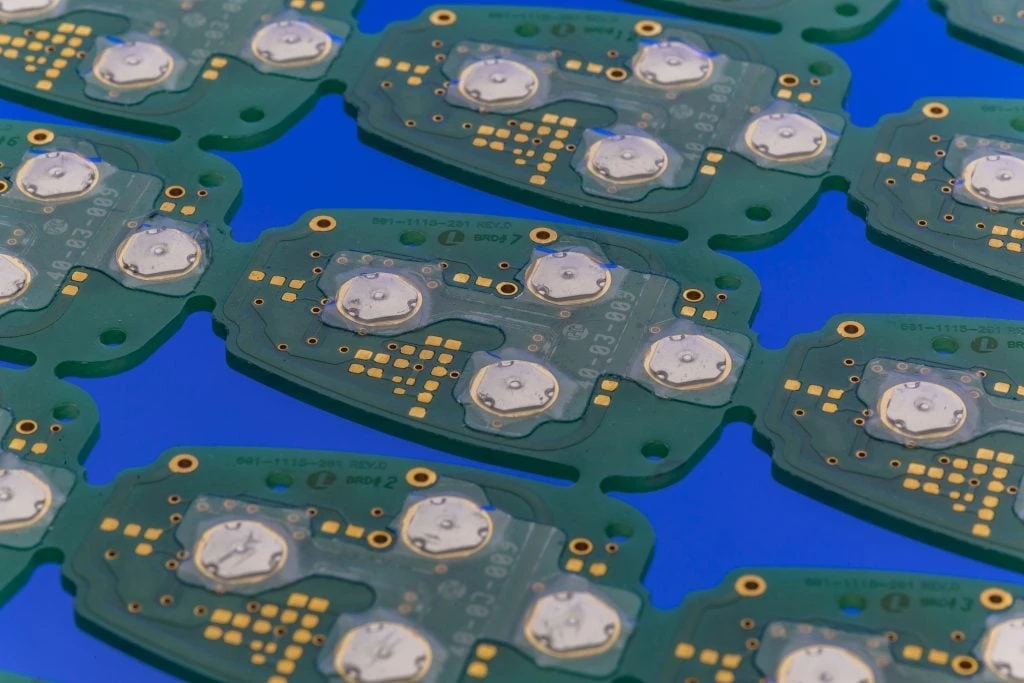
2.7 Stack integration: spacer, venting, preload, overlay, support surface
The dome only works inside the stack:
Graphic overlay + emboss / actuator
Adhesive / retainer or dome-array carrier
Metal dome
Spacer (sets gap) + vent channel
Circuit: PET silver / FPC / PCB pads
Rear adhesive + support surface / backer
The spacer sets the pocket and adhesive land around the dome. Vent channels between pockets, top vents through an array carrier, and through-board vents provide controlled air routes during collapse. Trapped air significantly reduces tactile response. Overlay or retainer preload also changes effective force and travel: a stiff overlay can make a lower-force dome feel heavy, while a compliant support can absorb the snap.
Drawing shows vent path, spacer pocket size, emboss type, and mounting surface flatness notes.
Fully sealed decorative overlay with no planned air path around dome pockets.
2.8 Single-force board vs mixed-force zoning
Not every key earns the same force. Numeric entry keys often run lighter. Mode and navigation keys sit in the middle. Safety confirmation or e-stop-style membrane keys (where used) run firmer. Mixed-force layouts require a BOM map from key ID to dome part number and a controlled assembly method (multi-bin tray or coded array). The benefit is operator clarity by touch. The cost is process discipline.
Key legend table includes force column and dome P/N.
“Make the emergency key feel different” with no part change and no sample plan.
2.9 Retention: loose domes vs dome arrays
Low-volume builds may place loose domes into a die-cut retainer. Production builds may use a metal dome array with domes pre-located on a polyester carrier. The Snaptron array overview documents single-dome tape pieces and custom carriers laid out to a circuit. Array versus loose placement is mainly an assembly, alignment, and yield decision; feel still comes from the dome and the completed stack. Waterproof or wash-down panels need controlled vent routing plus sealing review at every adhesive and gasket interface.
Assembly process defines placement accuracy and verification (vision or fixture).
Hand placement with no alignment marks on a dense 40-key board.
2.10 Validation: curves, tolerances, and cycle tests with conditions
Selection is incomplete until samples pass the same tests production will use. At minimum:
| Check | What to measure | Notes |
|---|---|---|
| Force-displacement | Fmax, Fmin, travel | Prefer plot, not only a single gf number |
| Pre-conditioning | Stabilize sample | Snaptron's method uses 10 actuations, then captures data on cycle 11 |
| Lot force window | Sample of incoming domes | Use the selected part tolerance; catalogs show both fixed-gram and percentage tolerances |
| Contact resistance | Closed circuit | After humidity/thermal if the environment demands it |
| Life / cycle test | Feel and electrical continuity vs cycles | Report force, fixture, over-travel, rate, and failure criteria |
| Full-stack feel | Assembled keypad | Overlay + vent + housing as used in the field |
Snaptron's force-test procedure specifies a flat probe, hard vented surface, centering, test speed, and preconditioning. Record the fixture. It references ASTM F2592 for force-displacement work, but ASTM lists F2592-16 as withdrawn in 2023. For cycle testing, ASTM F1578-24 is active and covers repeated membrane-switch actuation. State the method revision and fixture instead of writing “ASTM tested” without detail. Related constructions are covered on the tactile membrane switches page, and finished-assembly controls belong in the manufacturer's quality and testing process.
First-article pack includes F-D data for the approved dome and a written feel acceptance note from the OEM.
Life claim with no test condition; or sample approved by “feels fine in the conference room.”
3. Step-by-Step Selection Process
Step 1 — Capture the operator and environment profile
List glove use, presses per key per shift, indoor vs outdoor, chemicals, vibration, and whether the operator looks at the panel. High-rate data entry and rare confirmation keys should not share a force assumption. Note whether the product is handheld or fixed-mount.
Step 2 — Freeze the key map and tactile dome size targets
For each key: graphic size, emboss style (rim, pillow, flat), center spacing, and whether the finger or a stylus hits the target. Assign a candidate tactile dome size class before picking force. If waterproof gasket rules force large clearances from emboss to edge, fix that geometry early—late spacing changes are expensive.
Step 3 — Assign membrane switch dome force and snap intent by zone
Write a force column: light / medium / firm with numeric targets. Add snap language (crisp confirmation vs soft tactile). Where mixed forces help, map zones on the legend. Keep accidental-activation keys firmer than high-frequency keys.
Step 4 — Choose geometry, plating, and circuit type together
Align dome outline to pad artwork. Pick PET silver, FPC, or PCB for the electrical and mechanical stack. Select plating only after contact-resistance and environment needs are clear. Component OEMs (for example Snaptron) and membrane assemblers should see the same pad drawing.
Step 5 — Design spacer, venting, preload, and support surface
Set spacer thickness to the dome travel. Draw vent channels between pockets or to a controlled exhaust. Check overlay stiffness and emboss depth so the operator force is not wasted crushing plastic. Specify the rigid or semi-rigid support behind the circuit so the dome has a hard reference plane.
Step 6 — Build comparative samples and approve on data
Order side-by-side boards with two or three force options when feel is subjective. Measure F-D curves after pre-conditioning. Have production operators, not only engineers, press the samples in representative gloves. Record the winner by part number and lot criteria.
Step 7 — Lock the RFQ package
Send drawings plus: target force, travel, key diameter, snap preference, life target with test method, circuit type, plating, IP/sealing goal, connector, annual volume stage, and sample plan. A clear package shortens quote cycles and prevents “catalog default” domes from landing in your tool.
4. Release Blockers and When a Metal Dome Is the Wrong Choice
These issues override a pretty force table:
- No vent path in a sealed-looking stack—prototype feel will not match production after full lamination.
- Force chosen from habit (default “always 280 g”) with no operator or glove review.
- Dome larger than the emboss or centered poorly under the graphic.
- Housing crush that preloads or over-travels the dome after install.
- Life number without conditions—supplier, force, fixture, rate, and failure criteria missing.
- Gold plating as a substitute for process control on dirty or misaligned contacts.
- Mixed-force intent without BOM control—assembly will randomize the feel.
- Approval by email photo instead of physical F-D / operator sample.
Metal dome tactile construction is not the best choice when:
| Better fit | Why metal dome loses |
|---|---|
| Polydome / embossed poly tactile | Lower cost, thinner stack, moderate duty, softer feel acceptable |
| Non-tactile membrane | Flat sealed surface, wipe-down priority, no click required |
| Silicone rubber keypad | Long travel, 3D key shape, heavy industrial gloves, strong cosmetic keysets |
| Capacitive touch panel | No mechanical wear, sealed glass aesthetic, non-gloved clean environments |
| Discrete mechanical switches | Extreme cycle life or repairable single-key service model |
If the product only needs a soft confirmation and low annual press counts, paying for metal domes and array tooling can be pure waste. If the product needs deliberate gloved confirmation for years of industrial duty, polydome shortcuts usually fail the operator long before the PCB does.
5. Frequently Asked Questions
What is metal dome selection for membrane switches?
It is the process of choosing dome force, snap ratio, diameter, geometry, plating, and stack details so a tactile membrane keypad closes the circuit with a controlled click. Selection is incomplete until the dome is approved inside the real overlay, spacer, vent, and support surface—not only as a loose part.
How should engineers choose membrane switch dome force?
Start from operator duty, then compare two or three available part numbers in the intended dome family. Values such as 180 gf, 280 gf, and 350 gf can be useful sample points when available, but they are not universal light, medium, and firm specifications. Approve the chosen part on a full-stack force-displacement sample.
What is snap ratio on a metal dome?
Snap ratio (tactile ratio) describes how sharp the collapse feels. Snaptron defines it as (Fmax − Fmin) / Fmax × 100. Higher values feel snappier; lower values feel softer. Overlay and preload can change the felt ratio even when the bare dome is unchanged.
What tactile dome size fits a membrane key?
Pick a diameter whose documented pad, cavity, actuator, vent, and adhesive-land dimensions fit the key stack. The 6–8 mm, 10–12.2 mm, and 14–16 mm bands are useful layout screens, not release dimensions. Check the selected part drawing, off-center actuation risk, pitch, emboss, and gasket clearance before freezing the legend.
Is a four-leg dome always better than a three-leg dome?
No. Four-leg parts are common general-purpose options for balanced loading. Three-leg or triangle parts can fit tight layouts or specific pad designs. Oblong and specialty shapes follow rectangular or custom keys. Match geometry to the pad and assembly method.
Why does a metal dome membrane switch feel mushy?
Common causes include missing venting, wrong spacer gap, excessive overlay stiffness, too much preload, soft support under the circuit, misalignment, or adhesive contamination. Re-test the same dome in a corrected stack before changing the force rating.
Can one keypad mix different dome forces?
Yes. Mixed-force zoning is a normal practice for numeric vs mode vs confirmation keys. Document each key’s dome part number on the BOM and control placement in assembly so the feel map does not drift lot to lot.
Do metal domes always outlast polydomes?
Not as a universal rule. Metal domes are often chosen for crisper feel and higher life targets, but actual life depends on the supplier part, force, geometry, stack, and test method. Polydomes can be the correct, lower-cost choice for lighter duty. Never write a cycle number without the test condition.
When should gold-plated domes be specified?
When contact resistance stability and corrosion risk justify the cost—for example low-level signals, humid or corrosive environments, or long idle times. For simple dry indoor appliance panels, bare stainless or nickel may be enough. Plating does not fix stack defects.
What package should a manufacturer receive to quote metal dome membrane switches?
Share the key map, target force, travel, key diameter, snap preference, circuit type, plating, sealing goal, connector, environment, volume stage, and whether you need comparative samples. Those three mechanical targets—force, travel, and key diameter—remove most guesswork from the first quote.
6. What to Do Next
Metal dome selection for membrane switches succeeds when force, snap ratio, and tactile dome size are treated as stack variables with a written approval method. Use the ten criteria above, build comparative samples, and reject bare-brochure life claims that omit test conditions. For production intent, start from the metal dome membrane switch construction options, compare related tactile membrane switch approaches when metal is optional, and align first-article checks with the plant’s testing workflow.
Compare the full stack before releasing one force
Send the key map, candidate force range, available diameter, overlay, actuator, enclosure stack, glove profile, and environment. JASPER Engineering will define a controlled comparison sample and acceptance record.