
ANSI/AAMI EC12 disposable ECG electrodes should be selected as a complete, packaged interface—not by pad diameter or conductor label alone. For an OEM device, define the intended recording function, contact duration, electrode geometry, substrate, Ag/AgCl system, hydrogel or adhesive, connector, liner, package, shelf-life evidence and validation owner; EC12 supplies important labeling, safety and performance inputs, but it does not establish patient compatibility, clinical performance, finished-device approval or universal material specifications. The OEM must translate the intended use into a released stack and a risk-based verification plan.
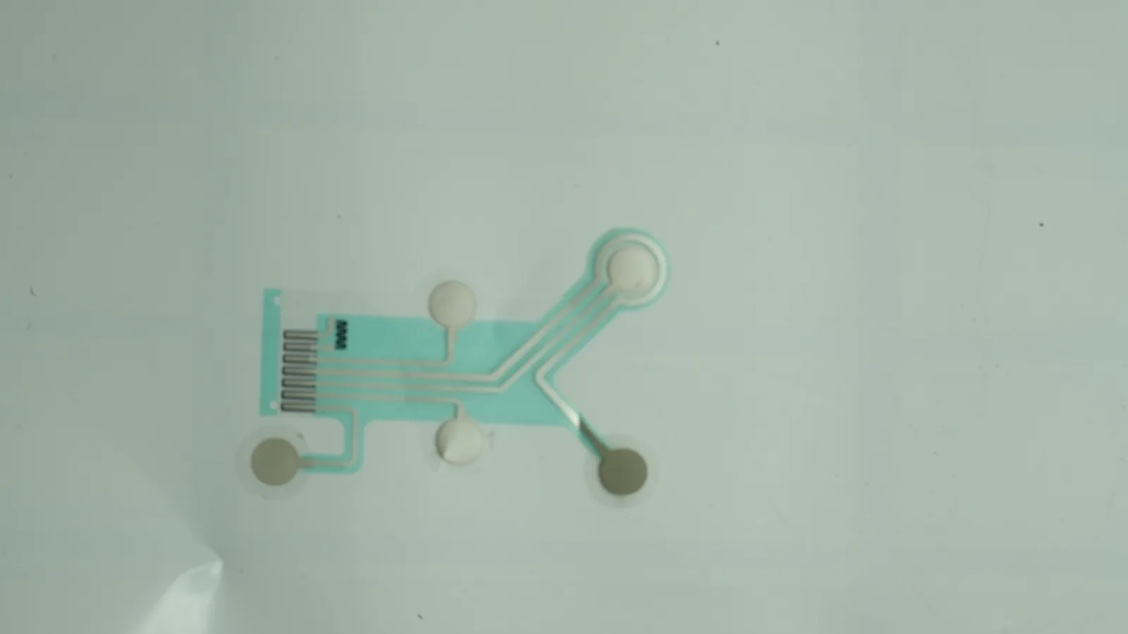
This JASPER guide explains how to specify printed medical electrodes for an OEM program. Printed components do not confer diagnosis, patient compatibility or finished-device approval.
Quick decision table: select the evidence package before the material stack
The right construction traces intended use to measurable inputs and finished-device verification. Assign the decision owner before selecting materials.
| Decision | Minimum input before RFQ | Evidence expected before release | Stop condition |
|---|---|---|---|
| Recording, stimulation or another function | Intended function, waveform or energy boundary, device architecture | Applicable standard and regulatory-pathway rationale | Treating recording and stimulation electrodes as interchangeable |
| Body-contact boundary | Contacting layers, anatomical site, contact duration, user population | Biological-evaluation plan for the final contacting construction | A raw-material declaration is offered as finished-device biocompatibility |
| Printed stack | Site map, traces, substrate, ink, dielectric and converted outline | Approved drawing, bill of materials, process window and agreed acceptance tests | “Ag/AgCl on PET” is the entire specification |
| Skin interface | Hydrogel and/or pressure-sensitive adhesive zones, wear and removal conditions | Adhesion, fluid, motion and aging tests under defined use conditions | “Hypoallergenic” replaces material identity and test evidence |
| Connector | Mating cable/device, snap or tail drawing, load direction and assembly sequence | Mechanical fit, electrical continuity and system-level cable-safety evidence | Compatibility is judged from a photograph |
| Package and expiry | Nonsterile or sterile state, pouch/liner system, storage and distribution profile | Packaged-product aging and post-aging functional tests | Shelf life is copied from another material or electrode |
What are disposable medical electrodes?
Disposable medical electrodes are single-use interfaces that connect a body-contacting or application-contacting medium to an electrical circuit; in a recording electrode, the stack commonly converts ionic activity at the skin interface into an electronic path through a conductive contact, trace and connector. A disposable electrode pad may be a small round snap part, a tab electrode, a pre-attached lead, or a multi-site printed patch.
“Disposable electrode” does not identify one construction or one regulatory category. ECG and EKG are equivalent abbreviations, but an ECG recording electrode, an EEG or EMG electrode, a stimulation pad and an electrosurgical return electrode have different functions and hazards. FDA's 2020 recording-electrode guidance is expressly limited to non-invasive, single-use recording electrodes used with electroconductive media on normal, healthy, clean, intact skin; that pathway excludes stimulation, MR use, reuse and dry electrodes. The intended function therefore comes before the material choice in a Custom Medical Electrode Design Guide.
The layer stack, application site, cable load and acquisition electronics act together. An OEM drawing must describe those interfaces instead of naming only a familiar catalog shape.
ANSI/AAMI EC12 defines disposable ECG electrode performance inputs, not the whole OEM approval case
ANSI/AAMI EC12 establishes minimum labeling, safety and performance requirements for disposable ECG electrodes used for diagnostic ECG or monitoring. AAMI publishes ANSI/AAMI EC12:2000/(R)2020. FDA's database, updated May 25, 2026, lists ANSI/AAMI EC12:2000/(R)2015 with partial recognition excluding section 5.3.2 on pre-attached leadwire safety. A U.S. regulatory file should identify the exact edition and current extent of recognition.
FDA's 2020 Safety and Performance Based Pathway guidance publishes the following criteria for the cutaneous recording electrodes within its scope. These values are useful design inputs, but the complete test setup, conditioning, sample handling and reporting must follow the applicable licensed method and regulatory strategy.
| Characteristic | Public FDA criterion | Stated condition | OEM implication |
|---|---|---|---|
| AC impedance, pair average | Maximum 2 kΩ | Average 10 Hz impedance for 12 electrode pairs | Define the finished electrode pair, gel state, conditioning and sampling plan—not only printed trace resistance |
| AC impedance, individual pair | Maximum 3 kΩ | Each pair within the same method | Control tails in the distribution, not just the lot average |
| Offset voltage | Maximum 100 mV | ANSI/AAMI EC12 method cited by FDA | Ink, gel, contact and process interactions remain part of verification |
| Combined offset instability and internal noise | Maximum 150 µV | ANSI/AAMI EC12 method cited by FDA | A low-resistance printed trace alone does not establish electrode noise performance |
| Bias current tolerance, DC offset | Maximum 100 mV | ANSI/AAMI EC12 method cited by FDA | Include the acquisition input and use condition in system verification |
| Pull-test adhesion | No more than 5% adhesive-area separation in at least 90% of tests | FDA cites the IEC 60601-2-2 (2016) pull method | Translate the method into a controlled specimen, skin surface and loading procedure |
| Conformability | No more than 10% adhesive-area separation 1 hour after application | FDA-cited conformability method | Geometry, backing stiffness and adhesive zone interact |
| Fluid tolerance | No more than 10% adhesive-area separation within 15 minutes after saline is poured | FDA-cited fluid-tolerance method | Sweat/fluid claims need a defined challenge rather than a water-resistant adjective |
| Shelf life | Tests 1–5 still pass | Real-time or accelerated-aged samples tested within 30 days of labeled expiration | Age the final packaged construction and repeat functional acceptance tests |
FDA's ECG electrode guidance also identifies defibrillation overload recovery among relevant electrical characteristics. Test selection depends on intended use, device interface and submission route. EC12 does not by itself establish biological safety, sterile-barrier integrity, MRI safety, radiolucency, clinical signal quality or finished-device clearance. Keep those evidence areas separate in the design input, risk file and supplier agreement.
A disposable printed-electrode stack is a controlled system of seven interfaces
A printable conductor is only one layer. The released component must control each interface from the skin-side liner to the device connection. The Medical Electrode Layer Stack Design Guide provides broader stack context; the table below focuses on a disposable recording-electrode RFQ.
| Layer or interface | Engineering job | Inputs to release | Common failure path |
|---|---|---|---|
| Release liner | Protects adhesive or hydrogel and supports handling until application | Material, thickness, release side, cut pattern, pull direction and storage orientation | Excess release force distorts the patch; low release allows edge lift or gel exposure |
| Hydrogel / skin adhesive | Provides ionic contact, fixation, or both, depending on design | Supplier grade, contacting zone, coat or converted thickness, aperture, contact duration, storage and removal conditions | Drying, ooze, edge lift, residue, irritation risk or changing interface impedance |
| Electrode contact | Couples the ionic interface to the electronic conductor | Ink or contact material, exposed geometry, Ag:AgCl formulation where applicable, cure and surface acceptance | Polarization, offset, contamination or chemistry drift |
| Printed trace and dielectric | Routes the signal and isolates unintended conductive areas | Trace geometry, print thickness acceptance, cure window, dielectric overlap, insulation clearance and test points | Cracking at bends, shorts through gel, incomplete coverage or registration error |
| Substrate and backing | Carries print and controls flexibility, handling and conformability | Polymer/grade, thickness, surface treatment, bend zones, backing lamination and converting process | Buckling, delamination, excessive stiffness, creep or process incompatibility |
| Snap, stud, tab, tail or lead | Transfers the signal into the cable or device | Mating drawing, materials, stack reinforcement, attachment process, load direction and electrical acceptance | Intermittent contact, rotation, tear-out, corrosion or mismatched mating geometry |
| Primary package and label | Preserves the approved state through storage and distribution | Pouch/packet materials, seal, count, orientation, storage limits, lot/expiry data and sterile/nonsterile status | Moisture loss, gel migration, seal damage, label mix-up or an unsupported expiry claim |
Ag/AgCl ink is not a commodity description. DuPont's MCM 5881 is one polyester-film screen-printing formulation, and its datasheet says typical data should not set specification limits alone. Henkel's LOCTITE EDAG PE 409 has a different documented formulation and process. Name the exact product and cure; do not assume Ag/AgCl inks can share a screen, gel or substrate.
Pregelled electrodes incorporate electroconductive media before use. The gel reduces electrode–skin interface impedance, but peer-reviewed literature also documents dehydration as an extended-wear failure mechanism. The OEM therefore needs an initial performance target and an end-of-use/end-of-shelf-life target. “Pregelled” describes supply state; it is not proof of wear duration or patient compatibility.
Ten evaluation criteria turn application needs into a releasable electrode specification
The strongest supplier selection framework evaluates ten linked criteria. A weakness in one can invalidate an otherwise attractive stack, so the table pairs a good signal with a disqualifying pattern.
| # | Evaluation criterion | Good signal | Red flag |
|---|---|---|---|
| 1 | Intended function and regulatory boundary | Written recording/stimulation function, population, body site, contact duration, reuse status and target markets | “Medical electrode” or “EC12 compliant” is treated as a complete intended use |
| 2 | Geometry and site map | Dimensioned outline, active area, spacing, datums, tail direction, cable load and tolerances tied to device fit | A sample photo or overall diameter is the only geometry input |
| 3 | Substrate and backing | Exact grade and thickness, print-surface treatment, bend zones, lamination and converting requirements | Generic “PET,” “foam” or “nonwoven” with uncontrolled substitution |
| 4 | Conductive/contact system | Ink part number, lot control, print/cure window, exposed contact area, inspection and electrical acceptance | “Silver” or “Ag/AgCl” without formulation, process or acceptance method |
| 5 | Hydrogel and adhesive boundary | Contact map, supplier grade, liner pairing, storage, wear/removal conditions and biological-evaluation ownership | “Skin safe” or “hypoallergenic” replaces composition and device-specific evidence |
| 6 | Connector and interconnect | Controlled mating drawing, assembly stack, reinforcement, mechanical loads and electrical continuity method | A nominal snap size is assumed to mate with every lead |
| 7 | Dielectric and isolation | Defined keep-outs, overlaps, apertures, gel migration boundary and inspection/test method | Conductive traces can contact gel outside the intended site |
| 8 | Packaging and shelf life | Finished package specification, storage/distribution profile, lot coding and aged functional test plan | An expiry date is inherited from raw gel or pouch data |
| 9 | Biological and chemical evidence | Final contact map, full contacting BOM, manufacturing/residue assessment and ISO 10993 risk plan owned by the legal manufacturer | One supplier certificate is called “biocompatibility of the electrode” |
| 10 | Quality and change control | Approved critical-to-quality characteristics, traceability, nonconformance route, change notice and requalification triggers | Silent material, tooling, process or packaging substitutions are allowed |
Geometry must describe the functional area, not just the die-cut outline
A circular pad's outer diameter does not reveal active area, adhesive annulus, snap position, backing stiffness or cable load moment. A “1-inch” pad is 25.4 mm in nominal outside diameter, but it is not interchangeable by diameter alone. Specify tolerances, contact aperture, connector location, liner tab and mating envelope. Likewise, SEN010C, BlueSensor and Go Direct EKG are catalog identifiers, not open form standards. Convert reference samples into neutral requirements and verify them independently.
The connector is part of the signal and safety boundary
The electrode drawing should control the snap/stud or tail interface and the receiving cable. FDA's EC12 recognition note excludes one pre-attached leadwire section, while FDA guidance points leadwire safety to separate cable and medical-electrical-equipment requirements. That is a warning against using one certificate to cover the whole connection chain.
Connector review should reach the enclosure and user interface when the electrode is bundled with equipment. The related HMI Hardware for Medical Equipment and Industrial HMI Standards and Hardware Compliance guides place the consumable interface inside the broader hardware and compliance architecture. Those internal routes provide design context, not evidence for electrode performance.
Packaging evidence must follow the product's claimed state
Prepackaging protects the approved interface and supports lot identification only if the liner, pouch, seal and storage conditions preserve it through expiry. ISO 11607-1 is not applicable merely because an electrode is pouched: its official scope concerns maintaining sterility of terminally sterilized medical devices. A nonsterile electrode still needs fit-for-purpose barrier and stability evidence.
ASTM F1980-21 also requires a scope check. It says real-time aging must run in parallel with accelerated aging and does not replace distribution-event testing. FDA's electrode guidance gives the direct product requirement: age the final package and confirm critical performance near labeled expiry.
Pregelled disposable electrodes are not the best choice for every OEM architecture
Pregelled Ag/AgCl electrodes suit many non-invasive recording systems because the medium is present at application. They are a poor default for reuse, dry interfaces, stimulation, unsupported MR claims or storage incompatible with the gel and package.
Other trade-offs are application-specific:
- A soft, conformable backing can follow body contours, yet it may complicate liner removal, connector reinforcement or automated placement.
- A strong skin adhesive can resist cable load, yet removal and skin-risk inputs must still be evaluated for the intended population and duration.
- A compact round electrode saves space, yet less adhesive area can raise sensitivity to cable loading and placement variation.
- An offset connector can separate cable disturbance from the active site, yet it adds geometry, orientation and converting constraints.
- A dry electrode avoids gel dehydration, yet it falls outside FDA's 2020 Safety and Performance Based Pathway guidance for cutaneous recording electrodes and needs its own evidence strategy.
Do not release a design when ownership of skin-contact materials, duration, mating cable, aging or finished-device validation is undefined. A supplier can manufacture ambiguity; it cannot validate it away.
A six-step procurement process prevents evidence gaps from reaching production
An effective buyer process moves from intended use to drawing, evidence, samples, verification and controlled release. Procurement should not request price before the technical boundary is stable enough to compare like with like.
Step 1 — Freeze the intended-use and ownership statement
Record whether the electrode records, stimulates or performs another function; identify the body site, contact duration, patient/user population, environment, reuse status and target market. Assign owners for risk management, biological evaluation, system verification, packaging, sterilization if any, labeling and regulatory submission. If these inputs are unsettled, mark them as open design inputs rather than letting the supplier assume them.
Step 2 — Issue a controlled drawing and stack specification
The RFQ package should include the die-cut outline, active-site map, traces, dielectric, substrate, backing, hydrogel/adhesive zones, liner, connector or tail, reinforcement, package state and datums. Add the exact material grades when selected, plus acceptable alternatives only where a formal equivalence and approval route exists. Define visual, dimensional and electrical acceptance methods.
Step 3 — Build an evidence-and-responsibility matrix
For each requirement, name the source document, test method, specimen, condition, acceptance criterion and owner. Separate supplier process records from finished-device evidence. EC12 results, biological evaluation, adhesive wear, leadwire safety, device signal performance, package aging and distribution are different rows. Any blank owner is a project risk.
Step 4 — Approve prototypes against use-representative fixtures
Prototype lots should use declared materials and representative processes wherever possible. Check liner removal, placement, cable attachment, bend paths, connector engagement, trace continuity, registration and package handling. Use prototyping and sample approval to close drawing and assembly questions before an aged or formal verification lot is built.
Step 5 — Verify the packaged construction and finished system
Run the applicable EC12/FDA electrical and adhesion methods on the correct finished electrode configuration. Challenge fluid, motion, cable loading, storage and distribution conditions that follow from intended use. Repeat critical performance after aging. The OEM should connect component inspection to broader testing and validation planning without treating a supplier test as a substitute for device-system verification.
Step 6 — Release production controls and requalification triggers
Approve the drawing, bill of materials, inspection plan, packaging specification, labeling inputs and golden sample or objective master. Define lot traceability, retention records, nonconformance handling and notification timing. Material source, formulation, print/cure process, tooling, connector attachment, liner, package or sterilization changes should enter a documented impact assessment before use.
Eight supplier red flags should stop an OEM electrode award
These red flags outweigh a clean sample or an attractive quotation because they prevent the OEM from connecting production output to verified requirements.
- EC12 is cited without an edition, method, specimen or report. A logo or one-line declaration cannot show what was tested.
- The supplier promises FDA approval of the OEM's finished device. Component manufacturing does not transfer the legal manufacturer's intended use or submission responsibilities.
- Material identities are hidden behind generic names. “Medical-grade PET,” “silver ink” and “skin-friendly gel” are not controlled BOM entries.
- Raw-material biocompatibility is sold as final-device compatibility. Contacting composition, processing, residues, geometry and exposure still require evaluation.
- Connector compatibility is confirmed visually. Mechanical engagement, reinforcement, electrical continuity and leadwire safety need controlled interfaces.
- Shelf life comes from a gel or pouch datasheet. The claim belongs to the final packaged electrode and its critical performance attributes.
- Packaging status is ambiguous. Sterile and nonsterile supply require different labeling, process and evidence boundaries.
- Changes can occur without OEM review. Uncontrolled substitutions can invalidate drawings, aging data, biological evaluation and system verification simultaneously.
Finished-device validation remains with the OEM legal manufacturer
The cleanest contract assigns evidence to the organization that controls the relevant design decision. FDA's QMSR became effective February 2, 2026, incorporates ISO 13485:2016 by reference and applies to finished-device manufacturers that intend commercial distribution; FDA also notes that some components can themselves be accessories and therefore finished devices, so the legal status must be decided for the actual program—not inferred from the word “component.”
| Evidence area | Printed-component manufacturer can own | Shared handoff | OEM / finished-device owner retains |
|---|---|---|---|
| Geometry and stack | Process feasibility, drawing conformance, registration and die-cut inspection | Approved artwork, datums, tolerances and change notices | Device fit, placement and functional site map |
| Printed electrical structure | Ink/cure records and agreed component continuity/resistance checks | Test fixtures, sampling and acceptance data | EC12 applicability, electrode-pair performance and acquisition-system behavior |
| Skin interface | Controlled procurement/converting of specified adhesive or hydrogel | Material identity, lot traceability and process information | Contact classification, biological-evaluation strategy, wear/removal and patient-risk conclusions |
| Connector | Assembly process and agreed component checks | Mating drawings and sample interfaces | Cable/device compatibility, leadwire safety and use-related loads |
| Packaging | Build and inspect the released pack configuration | Seal/process data and aged samples as contracted | Package claim, storage/distribution validation, expiry and sterile status |
| Regulatory and clinical | Accurate component records within contracted scope | Technical file inputs that the supplier possesses | Intended use, risk management, labeling, submission, clinical claims and market authorization |
ISO 14971:2019 frames risk management across the medical-device lifecycle, while ISO 10993-1:2025 places biological safety within risk management using composition and exposure. Neither allows an OEM to outsource the conclusion to a material trade name. The practical boundary is simple: the supplier proves that the released component was built and inspected as agreed; the legal manufacturer proves that the finished device is safe and performs as intended.
Frequently asked questions
What are disposable medical electrodes?
Disposable medical electrodes are single-use electrical interfaces supplied as pads, tabs, leads or printed arrays. A recording version usually combines a conductive contact, trace or lead, electroconductive medium, attachment system, backing, liner and package. The term does not define one material stack, intended use or regulatory category, so an OEM must specify those attributes.
What does ANSI/AAMI EC12 require for disposable ECG electrodes?
ANSI/AAMI EC12 covers minimum labeling, safety and performance requirements and test methods for disposable ECG electrodes. Public FDA criteria tied to EC12 include AC impedance, offset voltage, combined offset instability/internal noise and bias current tolerance. The applicable edition, FDA recognition status, complete method and any additional electrode or system tests must be defined for the target market.
What is a pregelled disposable electrode?
A pregelled disposable electrode is supplied with electroconductive medium already incorporated at the contact interface. This can reduce application steps and lower the initial electrode–skin interface impedance. The gel identity, contact area, liner, package, storage condition, use duration and dehydration behavior still require specification and verification; “pregelled” is a supply-state description, not a performance claim.
What is the main advantage of prepackaged disposable electrodes?
The main advantage is a controlled, ready-to-use unit that protects the approved adhesive or hydrogel interface before application and supports lot and expiry identification. That advantage depends on the final package preserving the electrode through storage and distribution. A pouch by itself does not prove sterility, barrier performance or shelf life.
Is a 1-inch round self-adhesive snap electrode a universal form factor?
No. One inch equals 25.4 mm, but the outside diameter does not define active area, gel aperture, adhesive annulus, backing stiffness, snap material, stud geometry, connector location or tolerances. A 1-inch round electrode should be released against a mating drawing and functional specification, not treated as interchangeable by diameter alone.
Can BlueSensor, SEN010C or Go Direct EKG be used as an OEM specification?
No. These names identify brands, catalog products or equipment ecosystems rather than an open electrode standard. Use a reference sample only to derive neutral, measurable requirements such as geometry, active area, gel type, connector, backing, package and acceptance tests. Go Direct EKG replacement electrodes are identified by their manufacturer as educational products, not medical or commercial devices.
Does ANSI/AAMI EC12 compliance prove biocompatibility or FDA clearance?
No. EC12 performance evidence does not by itself establish biological safety, patient compatibility, sterile-package integrity, clinical performance, FDA clearance or approval of a finished device. The legal manufacturer must define the biological-evaluation, risk-management, packaging, system-verification, labeling and regulatory evidence appropriate to the intended device and market.
What should an OEM send with a disposable-electrode RFQ?
Send the electrode outline and active-site map; substrate, printed conductor/contact and dielectric stack; hydrogel or adhesive zones; connector or tail drawing; liner and package state; intended function and contact boundary; storage and use conditions; acceptance methods; regulatory markets; and a responsibility matrix for component testing, biological evaluation, aging and finished-device validation.
Project-input checklist for engineering review
Before requesting production pricing, assemble one controlled handoff:
- Electrode geometry, active-site dimensions, spacing, datums and tolerances
- Printed stack: substrate, ink/contact formulation, trace, dielectric, backing and reinforcement
- Connector: snap, stud, tab, tail or lead drawing plus mating interface and load direction
- Skin-interface boundary: hydrogel and/or adhesive material, zones, body contact, duration and removal conditions
- Liner, package, sterile/nonsterile state, labeled storage and shelf-life target
- Electrical, dimensional, visual, adhesion and post-aging acceptance methods
- Target markets, applicable standard editions and any FDA recognition rationale
- Named owners for risk management, biocompatibility, device-system verification, packaging, labeling and regulatory submission
- Change-control and requalification triggers
OEM teams can send drawings for engineering review with the electrode geometry, printed stack, connector, skin-interface boundary and validation ownership. When those inputs are controlled, request an engineering quote for the printed and converted component scope. JASPER's review is limited to manufacturability and agreed component evidence; the OEM retains finished-device validation and market authorization.
References
- Association for the Advancement of Medical Instrumentation. ANSI/AAMI EC12:2000/(R)2020 — Disposable ECG electrodes.
- U.S. Food and Drug Administration. Recognized Consensus Standards: ANSI/AAMI EC12:2000/(R)2015. Updated May 25, 2026.
- U.S. Food and Drug Administration. Cutaneous Electrodes for Recording Purposes — Performance Criteria for Safety and Performance Based Pathway. August 14, 2020.
- U.S. Food and Drug Administration. Electrocardiograph Electrodes — Class II Special Controls Guidance. October 2007.
- U.S. Food and Drug Administration. Quality Management System Regulation. Updated February 2, 2026.
- International Organization for Standardization. ISO 10993-1:2025 — Biological evaluation of medical devices, Part 1.
- International Organization for Standardization. ISO 14971:2019 — Application of risk management to medical devices. Confirmed 2025.
- International Organization for Standardization. ISO 11607-1:2019 — Packaging for terminally sterilized medical devices, Part 1. Confirmed 2024.
- ASTM International. ASTM F1980-21 — Accelerated Aging of Sterile Barrier Systems and Medical Devices.
- DuPont. MCM 5881 Ag/AgCl Conductive Ink for Healthcare Applications. Product sheet, 2022. Full source URL is recorded in the source ledger.
- Henkel. LOCTITE EDAG PE 409 E&C. Original supplier product data. Full source URL is recorded in the source ledger.
- Microsystems & Nanoengineering. Flexible dry electrodes for electrocardiographic monitoring: working principles, design strategies, and recent advances. 2025.
- Vernier. EKG Electrodes for EKG and Go Direct EKG sensors. Educational-use product documentation.
Bring the drawing, stack and operating conditions
JASPER engineering will review the interfaces, open risks and evidence required for a production quote.