
An HMI PC is an operator-interface system in which a display, touch input, computing platform, power path and machine interfaces are engineered as one hardware architecture. A dedicated HMI panel is usually the best fit for a fixed machine task and controlled runtime. An integrated panel PC fits local Windows or Linux applications and compact installation. A separate embedded computer plus touch display fits projects that prioritize independent upgrades, thermal isolation or field replacement. The choice applies to OEM engineering, quality and procurement teams; display stack, compute load, input/output, enclosure exposure, service strategy and supplier ownership matter more than the product label.
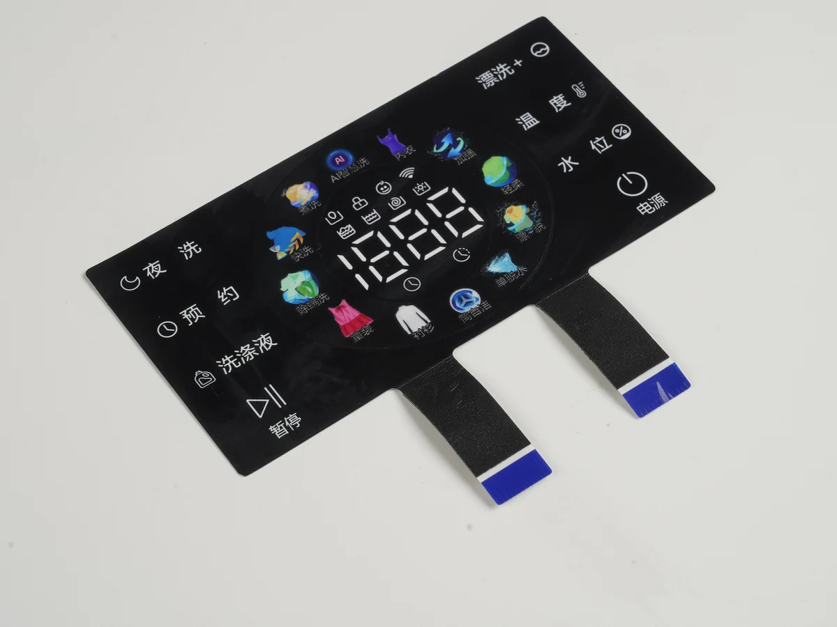
Quick decision: choose the HMI PC architecture by ownership and service boundary
The correct architecture puts each failure mode under an owner who can test and service it. Ownership comes first. Screen size follows. CPU choice follows.
| Architecture | Compute location | Best fit | Main integration burden | Main limitation |
|---|---|---|---|---|
| Dedicated HMI panel | Purpose-built terminal | Fixed tasks and a controlled runtime | Confirm PLC/network, cutout, power and environment | Tied to the terminal ecosystem |
| Integrated panel PC | Behind the display | Local PC software in a compact station | Remove combined compute/display heat; define whole-unit service | Display and compute lifecycles are coupled |
| Separate embedded/box PC plus touch display | Cabinet or protected bay | Independent upgrades, display variants or thermal separation | Engineer video, touch, power, ground and cable retention | More connectors and validation interfaces |
| Custom embedded HMI assembly | Carrier or single-board computer behind a custom stack | Product-specific design and bill of materials | OEM owns board support, integration, compliance and change control | Highest integration responsibility |
JASPER's HMI assemblies address the operator-facing hardware stack and its mechanical/electrical interfaces. For the broader definition of the operator panel itself, see What Is an HMI Panel? Hardware and OEM Guide.
An HMI panel, panel PC and embedded computer are different layers
HMI describes a function; panel PC describes a computer form factor. A physical HMI panel gives an operator information and input controls. It may contain a dedicated runtime terminal, a general-purpose industrial computer, or only a display and touch interface connected to compute elsewhere.
A dedicated HMI panel is a bounded appliance: display, touch, processor and engineering tool are selected together. A panel PC combines display and touch with a general-purpose computer. An embedded or box PC supplies compute without defining the front stack. “IPC HMI” and “HMI computer” are architecture descriptions, not purchasing specifications.
The visible panel does not identify who owns control. A PLC may retain machine logic while the terminal displays state and sends commands. IEC 61131-2:2017 applies where a product's primary purpose is industrial control equipment; it does not attach to every touch computer installed near a machine.
JASPER can integrate the cover or overlay, touch sensor, display, circuit interfaces, carrier, gasket and enclosure features. The OEM or controls partner owns application software, PLC/SCADA programming, operating-system policy and protocol behavior unless separately contracted.
The canonical HMI PC anatomy runs from the operator surface to machine input/output
A manufacturable HMI PC is a stack of optical, mechanical, electrical and thermal interfaces—not a screen bolted to a computer. Each arrow below is a drawing interface, test interface or supplier handoff.
OPERATOR / ENVIRONMENT
        │ touch, impact, cleaners, sunlight, ESD
        ▼
┌─────────────────────────────────────────────────────────────┐
│ 1  Graphic overlay or cover lens                           │
│ 2  Touch sensor + touch controller                         │
│ 3  Optical bond or controlled air gap                      │
│ 4  LCD/OLED module + backlight                             │
│ 5  Carrier, bezel, gasket and panel-mount compression      │
│ 6  Compute board, memory and storage                       │
│ 7  Power conversion, protection and grounding             │
│ 8  Ethernet/PoE, serial, USB, CAN, GPIO and video links    │
└─────────────────────────────────────────────────────────────┘
        │ commands, status, data and power
        ▼
PLC / DRIVE / SENSOR / NETWORK / REMOTE HOST
The operator surface defines chemical exposure, glare, color and legends. Touch must be tuned through the actual cover, adhesive, display noise and ground. The display fixes active area, viewing direction, resolution, interface and backlight power. Optical bonding couples those layers.
Carrier and bezel datums control display reveal, touch alignment, gasket compression and connector clearance. The enclosure transfers mounting load and heat. Compute and power set loss, boot behavior, storage access and input/output exposure. Ownership must be explicit. Machine connections add shield, isolation, cable-bend and service requirements.
If a supplier owns only the LCD, it cannot warrant the completed front seal. If the assembly supplier receives no display-noise profile, wet-touch criterion or enclosure flatness limit, touch remains underdefined. Name the design authority and verification owner at each layer.
HMI vs panel PC vs separate compute is a system partition decision
Choose the partition by compute workload, heat path, replacement unit and change-control owner. A compact enclosure is valuable only when the integrated unit can meet those four conditions in its installed state.
| Decision variable | Dedicated HMI panel | Integrated panel PC | Separate compute + touch display | Engineering implication |
|---|---|---|---|---|
| Application | Vendor runtime/toolchain | PC OS and local application | Host application independent of display | Name software and update owner first |
| Display variants | Terminal-family choices | Coupled to complete unit | Change while host stays fixed | Useful for several screen sizes |
| Input/output | Purpose-selected ports | PC plus industrial ports | Split by unit | Name electrical layer, isolation and protocol owner |
| Thermal path | Bounded appliance load | Compute/display share enclosure | Compute heat moves to cabinet | Test worst orientation and workload |
| Environment | Named terminal configuration | Front and whole-unit claims may differ | Two environmental boundaries | State evaluated surfaces, joints and entries |
| Replacement | Terminal | Complete panel PC | Display or host independently | Define image, calibration and restoration |
| Change control | Terminal vendor | Panel-PC supplier | OEM can qualify units separately | Require notice for critical substitutions |
A panel PC fits local PC software and scarce rear space. Coupling has a cost. A broken lens may retire a serviceable computer; a processor revision may force front-panel requalification.
Separate compute fits an exposed display with a cooler cabinet host, several display sizes or serviceable storage. Video, touch and power cables add EMC paths and installation steps; the interface drawing must control them.
A dedicated HMI panel fits a stable machine task and narrower software boundary. It is a different ownership model, not a low-performance panel PC.
Display, touch and front-panel integration must be specified as one stack
The display and touch specification is incomplete until it names the cover, bond, bezel, environment and acceptance method. The HMI Panel Assembly Design Checklist provides the related drawing context.
Define active area, resolution, viewing direction, color, illumination, glare and dimming, then the physical stack. An air gap eases independent replacement but adds reflecting surfaces and a controlled cavity. Optical bonding replaces it with a transparent bond layer, coupling materials, cure, rework and display stress.
PCAP alone proves little. The stack decides. Controller, sensor, cover, display noise, ground and tuning determine wet/gloved operation. Microchip's maXTouch controller documentation identifies water, noise, glove and thick-cover behavior as controller features. Define the actual glove, liquid, touch target, false-touch criterion and installed stack.
Resistive touch can suit deliberate single-point or stylus input. Its overlay, actuation and surface durability differ from bonded cover-glass PCAP. Select it by input condition.
Put cutout, radii, flatness, coating under the gasket, fasteners, clamp sequence, compression stops and display support on one drawing. Stack analysis must cover assembly and hot/cold installed states; a local tolerance can create pressure mura, edge lift, touch drift or seal loss elsewhere.
Compute, input/output and power integration needs named interfaces and owners
A port name is not an interface specification. The compute board, display, touch controller and machine network need compatible electrical layers, connectors, pinouts, cables, software ownership and grounding.
VESA defines embedded DisplayPort as the video interface from system graphics hardware to an internal panel in eDP 1.5. The design still needs lanes, timing, backlight control, connector, pinout and cable. LVDS or MIPI DSI likewise require an exact board-to-panel match.
USB-IF states that USB Type-C is not synonymous with USB 3.2, USB4 or USB Power Delivery in its USB Type-C product guidance. State data mode, host/device and power roles, required power, alternate mode, retention and cable length.
Texas Instruments' RS-485 introduction describes a balanced electrical standard, not the higher-level protocol. A “COM port” needs mode, connector, pinout, isolation, termination/bias owner, reference/shield plan and protocol. Industrial HMI Communication Protocols and Hardware Interfaces covers that adjacent boundary.
A PoE-powered HMI panel PC needs a budget covering compute, backlight, storage, peripherals, conversion loss and startup. IEEE 802.3-2022 provides power over selected twisted-pair PHY types; RJ45 alone proves neither PoE nor sufficient power. Record PSE, PD implementation, cable channel and low-power behavior.
Wireless functions add antenna location, RF transparency, grounding, coexistence and service inputs. Remote and Wireless HMI Hardware Design maps that branch without moving PLC/SCADA programming into assembly scope.
Thermal, enclosure and serviceability are coupled system properties
A fanless label does not prove that an installed HMI PC stays within component limits. It says only that the selected construction does not use a fan.
Model processor, memory, storage, conversion, display, backlight and peripherals. Add ambient, solar load, orientation, clearance, adjacent heat and sustained workload. Package data is not system data. Intel's processor thermal-management documentation separates processor package limits from system constraints. TDP is not the complete panel-PC heat load.
Define conduction contacts, interface materials, fastener load and flatness. A metal enclosure spreads heat only through intentional board-to-chassis and chassis-to-ambient paths. A front rating does not describe rear connectors, doors, vents or the cabinet cutout.
IEC 60529 classifies enclosure protection. The NEMA 250 boundary excludes internal condensation, thermal damage, icing and contamination through unsealed openings. Configuration controls the claim. Ingress, condensation and heat are separate requirements.
UL 50 and UL 50E evaluations can address corrosion, UV degradation and accessory sealing against a similarly rated flat surface. The assembly still depends on its opening, mounting surface, gasket compression and instructions.
Define the lowest replaceable unit and the image, calibration, firmware, seal and fastener steps that restore approved state. If service breaks a bond or thermal interface, the manual and spare strategy must control it.
HMI PC variants solve specific constraints and introduce specific limits
Variant names are useful only when the additional constraint and evidence are stated. The following table converts common search terms into engineering requirements.
| Variant | Constraint it addresses | Required evidence/input | Limitation or unsuitable condition |
|---|---|---|---|
| Compact/mini touch panel PC HMI | Shallow rear space or small cutout | Envelope, cable bends, heat path and usable touch targets | Less spreading area and service access |
| PoE-powered HMI panel PC | One cable for data and power | PSE/PD compatibility, power states, channel and fault behavior | Unsuitable above negotiated power allocation |
| HMI panel PC with serial ports | Legacy/industrial equipment | Mode, isolation, termination, pinout, shield and protocol owner | COM/connector labels do not define the interface |
| Outdoor HMI panel PC | Sun, precipitation and temperature cycling | Illumination, reflection, solar load, UV/chemicals, wet touch and installed test | Luminance or front IP Code alone is insufficient |
| Hazardous-location HMI panel PC | Ignitable gas, vapor, dust or fiber | Area classification, material, temperature, protection and approval | Ordinary industrial/washdown equipment is unsuitable |
| EN 50155 panel PC | Rolling-stock conditions | Edition, configuration, supply/environment categories, reports and change control | Component claims do not transfer to modified assemblies |
| Separate display + box PC | Independent service or thermal isolation | Video/touch/power, retention, ground and two-unit validation | More connectors and installation steps |
| Custom embedded HMI development | Product-specific front and electronics | Board support, display timing, touch, EMC, mechanics and lifecycle owner | OEM carries more verification and change control |
For a U.S. hazardous location, OSHA 29 CFR 1910.307 requires location-appropriate intrinsic safety, approval or demonstrated protection. The label is insufficient. Convert “Ex HMI panel PC” into the actual class/zone, combustible material, temperature and governing scheme.
EN 50155:2026 covers operating conditions, design, documentation, testing and integration of on-board electronic equipment. The project contract sets applicable evidence; display, storage, power or enclosure substitutions can change the qualified configuration. Evidence must follow.
Most HMI PC failures begin at an interface between owners
Failure prevention improves when the specification names the physical mechanism, detection method and responsible owner. Generic requirements such as “industrial grade” do not do that work.
| Failure path | Likely interface | Early evidence | Design control |
|---|---|---|---|
| False/missed wet or gloved touch | Cover, sensor, controller, display noise, ground | Installed-stack touch map | Tune actual stack; freeze configuration and ground |
| Edge lift, bubbles, optical artifacts | Cover, bond, display | Hot/cold inspection and process records | Define surfaces, bond, cure, rework and zones |
| Seal leak | Gasket, cutout, coating, flatness, clamp | Compression and installed test | Add stops, sequence and surface limits |
| Thermal throttling/discoloration | Compute, backlight, chassis, ambient | Worst-load/orientation logging | Size path for total loss and ambient |
| Intermittency after vibration | Cable, connector, carrier | Functional monitoring | Define retention, bends, support and fixture |
| Serial faults | Transceiver, reference, shield, termination | Electrical/traffic test on production cable | State mode/topology and termination owner |
| Service changes approved state | Part, image, calibration, seals | Replacement trial and audit | Define restoration, torque and checks |
IEC 60068-2-6:2007 supplies a sinusoidal-vibration method; IEC 60068-2-27:2008 covers shock. Severity is project-specific. The OEM must define fixture, operating mode and acceptance from the installation or product specification.
Validation must use the production-representative stack and installed state
A valid HMI PC test plan names the specimen configuration, exposure, operating mode, measurements and acceptance criteria. Component certificates can support the plan; they do not replace end-product evidence.
| Validation area | Input that must be frozen | Representative condition | Evidence to retain |
|---|---|---|---|
| Optical/display | Cover, bond/gap, display, backlight | Defined illumination, geometry, dimming and temperature | Visual limits, setup and part revisions |
| Touch | Sensor/firmware, cover, display, ground | Required glove, liquid and noise | Touch map, criteria and checksum |
| Thermal | Electronics, enclosure, mounting, workload | Maximum ambient, worst orientation, sustained load | Sensor map, traces, limits and workload version |
| Ingress | Gasket, cutout, coating, fasteners, entries | Installed orientation and exposure | Method, specimen photos and post-test function |
| EMC | Final cables, bonds, power and modes | Highest-emission/most-sensitive modes | Applicable standard, setup and results |
| Mechanical | Mass, fasteners, restraints, fixture | Derived shock/vibration | Axes, severity, duration and functional result |
| Service | Spares, files, seals and torque | Remove/replace/restore sequence | Work instruction and configuration audit |
Applicability comes first. When no dedicated product-family EMC standard applies, IEC 61000-6-2:2016 provides generic industrial immunity and IEC 61000-6-4:2018 generic industrial emissions requirements. IEC 62368-1:2023 addresses ICT/AV safety through energy sources and safeguards, not functional performance.
Start testing and validation planning before tooling and enclosure interfaces freeze. Use prototyping and sample approval to compare stack, drawing revision, touch configuration and installed mechanics—not cosmetics alone.
Frequently asked questions
What is an HMI PC?
An HMI PC combines or connects display, touch, compute, power and machine/network input/output for operator use. The term does not define sealing, operating system, PLC function or environmental qualification. Specify those properties for the actual assembly and installation.
What is the difference between an HMI panel and a panel PC?
An HMI panel is an operator-interface device or assembly; a panel PC is a computer with an integrated, usually touch-enabled display. A dedicated panel often uses a bounded runtime and toolchain, while a panel PC runs general PC applications. Either can show the same screen but assigns compute, maintenance and validation differently.
Can a panel PC replace a dedicated HMI?
Yes, when it supports the application, interfaces, boot/recovery behavior, environment and maintenance policy. Replacement is not automatically one-for-one. Validate licensing, protocol ownership, power states, storage recovery, touch behavior, EMC, thermal performance and the installed enclosure boundary.
Is a PoE-powered HMI panel PC practical?
It is practical when the IEEE 802.3 PSE and powered device supply every declared state, including startup, peak compute and backlight. Identify the PSE, cable channel, PD class/type implementation, fallback behavior and whether attached devices share the budget.
What should “HMI panel PC with serial ports” mean in an RFQ?
Name each port's electrical mode, connector, pinout, isolation, termination, bias, shield/reference and protocol owner. “COM1/COM2” is insufficient. For RS-485, define two- or four-wire topology, nodes, cable and which device supplies termination and bias.
Does an IP65 front rating make the complete unit waterproof?
No. A front rating applies only to the evidenced boundary and configuration. Rear connectors, openings, vents, cutout, gasket surface and installation may differ. IP Code testing does not by itself resolve condensation, chemical compatibility, UV exposure or thermal performance.
When does EN 50155 apply to a panel PC HMI?
EN 50155 applies to in-scope electronic equipment installed on rolling stock when the project invokes it. Require evidence tied to the edition, power input, environmental category, enclosure, display, storage and tested configuration. A component statement does not qualify an OEM-modified assembly.
Can an ordinary panel PC be used in a hazardous location?
Not solely because it is industrial, sealed or fanless. In U.S. workplaces, area classification and combustible material determine protection under OSHA 29 CFR 1910.307. The equipment and installation need location-specific evidence, temperature suitability and required markings.
Project-input checklist for an engineering review
Send a bounded input package so the front assembly, compute platform and enclosure can be reviewed as one system:
- Display size, active area, resolution, viewing direction and approved part or selection envelope
- Front-panel drawing: cutout, datums, flatness, coating, fasteners, rear clearance and cable exits
- Cover/overlay material, artwork, finish, cleaner/chemical list and impact condition
- Touch technology, glove/wet conditions, targets, firmware owner and acceptance criteria
- Interface stack: display, touch, Ethernet/PoE, USB, serial, CAN/GPIO, pinouts and cables
- Compute/storage configuration, power states, loads, operating system and validation workload
- Environment: ambient, illumination, ingress, condensation, shock/vibration, EMC and special standards
- Thermal boundary, orientation, adjacent heat and allowed temperatures
- Service units, restoration/calibration files, annual volume, ramp, prototypes and change control
Use send drawings for engineering review when the display size, front-panel drawing, interface stack, environment and annual volume are ready. If the architecture and responsibility split are already defined, request an engineering quote.
JASPER's scope is front-panel and HMI hardware assembly, including display, touch, overlay, circuit and enclosure interfaces. PLC/SCADA programming is outside that manufacturing scope.
References
- IEC 60529:1989+A1:1999+A2:2013 — IP Code.
- ANSI/NEMA 250-2020 — Enclosures for Electrical Equipment.
- UL 50/50E environmental-rated enclosure accessories.
- IEC 61000-6-2:2016 — Industrial immunity.
- IEC 61000-6-4:2018 — Industrial emissions.
- IEC 60068-2-6:2007 — Sinusoidal vibration.
- IEC 60068-2-27:2008 — Shock.
- IEC 62368-1:2023 — ICT/AV safety.
- IEC 61131-2:2017 — Industrial-control equipment.
- NEN-EN 50155:2026 — Rolling-stock electronic equipment.
- OSHA 29 CFR 1910.307 — Hazardous locations.
- IEEE 802.3-2022 — Ethernet.
- VESA eDP 1.5, 2021.
- USB-IF Type-C product guidance, 2023.
- Microchip maXTouch touchscreen controllers.
- Texas Instruments, RS-485 Basics.
- Intel processor thermal management, 2023.
Bring the drawing, stack and operating conditions
JASPER engineering will review the interfaces, open risks and evidence required for a production quote.