
LGF uniformity is a system output. Freeze the LED and drive state, coupling edge, extraction map, optical interfaces, overlay and mask, reflector, enclosure, and measurement method before approving the finished icon surface.
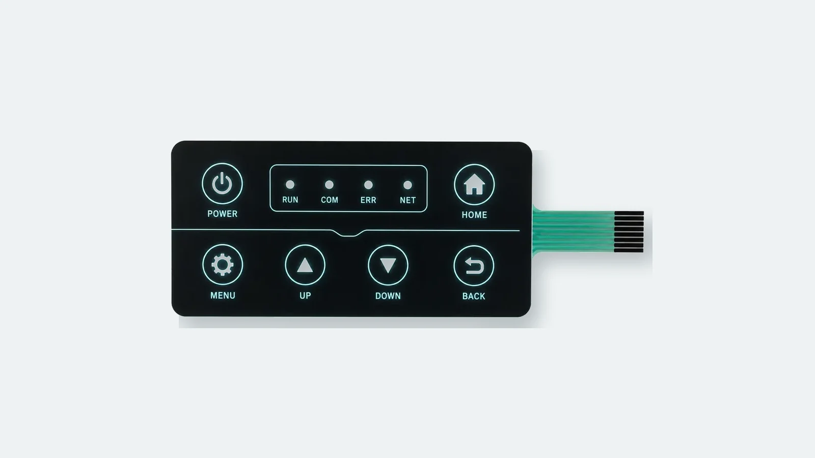
A light guide film membrane switch looks even only when the LED and drive state, coupling edge, extraction map, optical interfaces, overlay, mask, reflector, enclosure, and inspection method agree. This guide gives OEM engineers a design-to-validation method for controlling those variables and approving the finished icon surface. No public standard sets one universal keypad threshold. The released drawing must therefore define the region of interest, formula, operating states, viewing geometry, sample rule, and acceptance value for the actual equipment.
What a Light Guide Film Membrane Switch Is Actually Doing
A light guide film transports LED light laterally, then releases controlled portions of that light beneath the required icons. It does not create the electrical switching action, and it is not merely a diffuser. The circuit closes the contact; the LGF carries light; extraction features direct it out; the overlay and mask decide what the operator sees.
ams OSRAM divides a light-guide system into in-coupling, transport, and out-coupling. Inside the guide, rays that meet the boundary conditions for total internal reflection continue to travel. Printed dots, roughened areas, or microstructures disturb that condition and redirect light out of the guide (ams OSRAM, Light Guides, AN072).
Operator or luminance instrument
Graphic overlay: texture, ink, icon apertures, dead-front areas
Opaque mask and optional diffuser
Light guide film with controlled extraction map
Reflector and optical-isolation features
Spacer / circuit / side-emitting LEDs / tail
Rear adhesive and production enclosure
This is a functional stack, not a universal layer order. Dome height, circuit type, LED package, embossing, and the optical process can move or split layers. Release the backlit membrane switch architecture as one controlled assembly.
Four parts are easy to confuse:
- Extraction releases light from the guide at a chosen location.
- Diffusion spreads exiting light and can soften visible texture or a point source.
- Masking blocks light where it must not be visible.
- Reflection returns light that would otherwise leave through the back or edge.
One part cannot silently replace another. A darker mask may hide an LED fan without correcting the internal field. A stronger diffuser may smooth the field while lowering on-axis luminance. A reflector can improve delivered light yet expose crosstalk through an incomplete mask.
Seven Controls That Govern LGF Membrane Switch Design
Uniformity is controlled by seven linked design decisions. The extraction map can be tuned only after the other six are sufficiently stable; otherwise every mechanical or electrical revision changes the light field it was meant to correct.
| Control | Freeze in the released definition | Typical failure when it moves | Evidence to retain |
|---|---|---|---|
| LED source and placement | Manufacturer and part, optical axis, radiation pattern, pitch, color and brightness-bin policy | Bright fans, alternating bright/dark zones, color mismatch | LED datasheet, BOM, placement drawing, bin record |
| Input coupling | Guide-edge finish, LED alignment, mechanical datum, input gap | Low output, one source coupling better than another | Cross-section, datum scheme, assembly photos |
| Extraction map | Process, feature map, zone boundaries, revision | Bright near-source icons, dim remote icons, visible dot pattern | Controlled print/laser/tooling file and revision |
| Optical interfaces | Adhesive windows, intended air interfaces, diffuser contact, cleanliness, compression | Spots appearing after lamination or installation | Die line, stack drawing, surface-handling criteria |
| Overlay and mask | Ink build, icon transmission, opaque barriers, registration, dead-front target | Halos, ghost icons, pinholes, uneven edges | Color-separated artwork and tolerance |
| Reflector and enclosure | Reflector, edge treatment, housing color/texture, ribs, support points | Edge loss, local glare, housing-dependent patches | Enclosure material/finish and installed sample |
| Drive and thermal state | DC current or PWM on-current/duty/frequency, supply, dimming states, stabilization rule | Balance changing with dimming or warm-up | Controller revision, current log, temperature and optical map |
LED placement begins with the radiation pattern, not an LED count
The near-source mixing range changes with radiation pattern, LED pitch, guide geometry, material, and optical coupling. Put the LED optical axis, guide edge, and first permitted active artwork on the same controlled section. There is no defensible universal setback.
A smooth coupling face and a small, controlled air gap support efficient in-coupling in the cited AN072 configurations. “Small” is not a drawing dimension. The production assembly needs a datum and tolerance derived from the chosen LED and guide, then confirmed on samples.
The extraction pattern must spend light deliberately
Every extraction feature removes some light that would otherwise travel farther. A uniform dot field therefore tends to over-light the input region and starve the far end. ams OSRAM describes varying dot size or density, while 3M describes weaker extraction near the source and stronger extraction farther away (ams OSRAM AN072, pp. 6–7; 3M Optical Lighting Film 2405). Irregular icons, cutouts, multiple input edges, and independently switched zones normally require a two-dimensional map rather than a copied linear gradient.
Diffusion, masking, and enclosure reflection must be tuned together
A diffuser can hide microstructure and soften a hot spot, but angular spread, thickness, surface texture, source distance, and the chosen film construction change both homogenization and delivered luminance. Approve the selected diffuser in the production optical stack; values from another film construction do not transfer automatically.
Mask artwork must separate transparent, translucent, tinted, dead-front, and opaque areas. The reflector and production housing are part of the optical system. A white surface, glossy dark wall, support rib, local pressure point, contact mark, contamination, or fastener can alter the final extraction map. Approve the installed assembly, not a loose illuminated stack.
The drive state belongs in the optical specification
LEDs grouped at one current can diverge when driven at another. Forward-current changes can alter both output and chromaticity. PWM changes duty while holding on-current constant, but it still requires application-level validation. Test every drive state that the product will ship.
Diagnose Light Guide Film Hot Spots by Following the Light Path
Light guide film hot spots are symptoms, not a single defect. Start where the photons enter and change one controlled variable at a time. Adding diffusion before locating the cause can make a bad design less obvious without making it stable.
LED part / bin / drive
coupling face and alignment
transport and extraction map
diffuser and mask
reflector and enclosure
viewing or measurement geometry
| Visible symptom | First causes to check | Useful controlled experiment |
|---|---|---|
| Fan, crescent, or bright point near an LED | Active icon overlaps the mixing range; LED axis or pitch misses the input geometry | Move only the active aperture or compare one alternative LED placement while holding the stack fixed |
| Near icons bright, far icons dim | Extraction strength does not compensate for light removed upstream | Compare the measured map with the extraction revision; retune the gradient without changing the diffuser |
| Dots or mottling visible inside an icon | Extraction texture is visible through the available optical distance and overlay | Add one candidate diffuser or change the emitting surface; remeasure luminance and uniformity |
| An uncommanded icon glows | Shared optical region, mask opening, edge leak, or adhesive gap | Energize one zone at a time and inspect all neighbors; close one leakage path per trial |
| A spot appears only after lamination | Adhesive wet-out, contamination, scratch, or local pressure creates unintended extraction | Compare loose-stack and laminated maps using the same drive and camera setup |
| A patch appears only in the housing | Rib contact, reflector change, edge pressure, or enclosure reflection | Map the loose assembly and the installed assembly; correlate the difference with housing features |
| Balance changes with dimming or temperature | LED bins diverge away from the grouping current; output has not stabilized | Repeat the same ROI map at each production drive state after a documented stabilization condition |
If two variables change together—such as a new diffuser and a revised dot map—the result cannot tell the team which change fixed the problem. Keep an optical change log and preserve each raw luminance map.
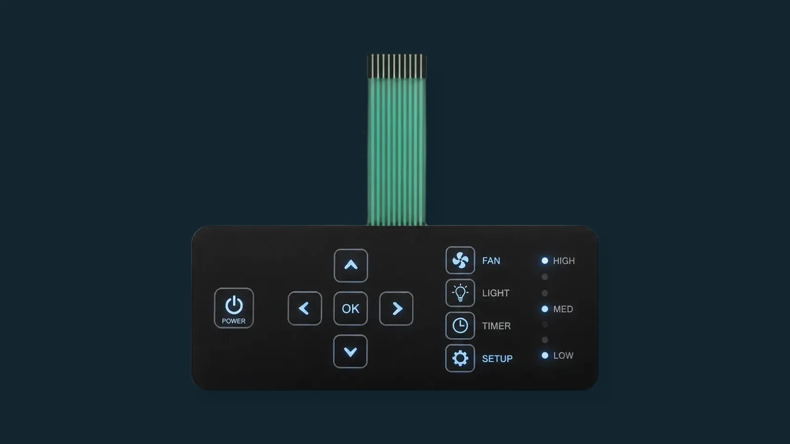
Specify Backlit Keypad Uniformity Before Asking for a Percentage
Backlit keypad uniformity should be specified as a luminance measurement at the finished icon surface. Illuminance on a bench is a different quantity. Radiant Vision Systems' backlit-character workflow reports symbol luminance, chromaticity, local extrema, key-to-key variation, and leakage from defined image regions (Radiant, Backlit Panels & Characters).
The CIE definition is concise:
Uo = Lmin / Lavg
CIE e-ILV 17-29-154 defines luminance uniformity as minimum luminance divided by average luminance of a surface (CIE S 017:2020). It does not define a keypad ROI, edge exclusion, sample grid, viewing angle, or pass threshold.
| Quantity | Report it as | What it answers | Boundary |
|---|---|---|---|
| Average icon luminance | Lavg, in cd/m² | Is the icon bright enough under the declared condition? | Needs an icon-shaped ROI and operating state |
| CIE luminance uniformity | Uo = Lmin/Lavg | How deep is the darkest point relative to the ROI average? | CIE supplies the definition, not the acceptance value |
| Minimum-to-maximum ratio | Lmin/Lmax | What is the full local contrast range? | Project-defined; do not label it Uo |
| Icon-to-icon balance | Lowest icon Lavg / highest icon Lavg | Do separate legends match one another? | Keep separate from within-icon uniformity |
| Leakage | Luminance in a declared unlit ROI or a declared lit/unlit ratio | Does a commanded zone contaminate its neighbor? | State which zones are powered and the ambient condition |
| Color difference | Declared chromaticity coordinates and, when required, Δu′v′ | Do icons or dimming states shift color? | CIE TN 001:2014 gives method guidance, not a keypad tolerance |
Freeze the measurement conditions
A percentage without conditions is not comparable. The approval method should state:
- final overlay, mask, LGF, reflector, adhesive, circuit, LED, controller, and enclosure revisions;
- supply, DC current or PWM on-current/duty/frequency, and every required dimming state;
- stabilization rule, installed orientation, ambient temperature, and enclosure temperature;
- ambient-light condition, instrument, calibration status, distance, focus/aperture, panel pose, and viewing angles;
- icon-shaped ROI rules, including anti-aliased edges, opaque strokes, emboss transitions, and dead-front borders;
- reported Lmin, Lavg, Lmax, Uo, leakage, and color fields; and
- sample quantity, lot selection, disposition rule, approver, and retained raw data.
CIE 244:2021 supports spatial luminance capture and region-based evaluation with an imaging luminance measurement device. ISO/CIE 19476:2014 addresses meter performance. Neither document certifies an LGF keypad or supplies its pass value.
Set the acceptance value from the equipment requirement
| Release field | Controlled definition |
|---|---|
| Surface | Final icon-shaped ROI at the installed overlay |
| Formula | CIE Uo = Lmin/Lavg, or another separately named project metric |
| Acceptance value | Stated in the drawing, optical specification, or validation plan for each required operating state |
| Required record | Lmin, Lavg, Lmax, drive state, thermal state, view, instrument, stack and enclosure revision |
| Disposition | Pass, rework, retune, or reject under a named revision and approval owner |
A supplier sheet may publish a percentage for an edge-lit panel, tape, diffuser, or light-guide material. That number cannot be transferred to a membrane keypad unless the formula, ROI, optical stack, viewing geometry, drive state, and sampling rule are the same. The useful question is not whether a keypad meets an isolated market percentage; it is whether the finished interface meets its declared requirement under repeatable conditions.
ASTM D1003 haze or transmittance data can help qualify a transparent film, but it cannot replace the assembled luminance map (ASTM D1003-21). Material transmission, icon brightness, and icon uniformity answer different questions.
Build, Test, and Release the Sample in Controlled Steps
A useful sample program fixes the high-impact interfaces early, then releases the optical design only after it has been measured in the final enclosure.
Artwork and lighting states
optical/electrical/mechanical stack freeze
first coupling and extraction sample
luminance-map diagnosis
one-variable optical revisions
installed verification and environmental recheck
signed data package and golden sample
| Test state | Hold constant | Record and decide |
|---|---|---|
| Nominal drive | Final controller, supply, LED policy, stack, and enclosure | Per-icon map; Lmin, Lavg, Lmax, Uo; leakage and visible defects |
| Minimum and maximum dimming | Production PWM or DC method | Same metrics at each shipped state; chromaticity when contractual |
| Stabilized output | Installed orientation and declared ambient | Stabilization time, temperatures, and repeated map |
| Normal and worst user views | Instrument geometry and panel pose | Luminance, uniformity, and legibility at each declared angle |
| One zone at a time | All neighboring zones commanded off | Crosstalk and edge leakage into each unlit ROI |
| Powered and unpowered | Declared dark and room-light conditions | Dead-front ghosting, pinholes, registration, complete icon shape |
| Loose versus installed | Same optical/electrical assembly | Difference map that isolates pressure, rib, reflector, or housing effects |
| Repeat or lot check | Same released method | Distribution, outliers, disposition, revisions, and approver |
When temperature change or humidity is part of the product environment, select the severity from the finished-product requirement and repeat the optical map afterward. IEC 60068-2-14:2023 and IEC 60068-2-78:2025 provide temperature-change and damp-heat methods; they do not supply a default keypad severity or pass criterion.
Retain the raw maps, named test conditions, photographs, BOM and LED-bin policy, artwork, extraction and stack revisions, enclosure revision, controller revision, disposition, and signed golden sample. Link ownership and retest triggers to testing and validation planning.
When LGF Is the Wrong Backlighting Architecture
LGF is a strong choice when a thin assembly must distribute light across several legends or a wider area. It is not automatically the simplest or lowest-risk option.
| Architecture | Best fit | Do not choose it by default when | Approval emphasis |
|---|---|---|---|
| Edge LED + LGF | Thin, distributed illumination across multiple icons or zones | There is no mixing border; each icon requires strict optical isolation or independent color | Coupling, extraction map, crosstalk, installed uniformity |
| Direct LED + local diffuser | One or a few indicators with independent control | A large thin surface must read as continuous and package height exposes point sources | LED height, aperture, diffuser distance, local hot spot |
| Electroluminescent area source | Broad, soft area illumination with an accepted driver architecture | The system cannot accommodate the driver, electrical integration, or application-specific aging/environmental validation | Driver, powered brightness, environment, change over service life |
| Remote LED + solid or fiber path | Heat or electronics must be separated from the visible control area | Routing, bends, terminations, coupling loss, or service access dominate the assembly | Route control, bend/termination, installed loss, serviceability |
The wider membrane switch backlighting options should be evaluated before committing artwork and enclosure space to LGF.
RFQ and Drawing Checklist for a Useful First Sample
“Bright,” “even,” and “no leakage” are review comments, not release criteria. Send the following as controlled inputs.
| Input | Minimum useful content |
|---|---|
| Icon artwork | Vector geometry, lit/unlit colors, opacity class, dead-front regions, simultaneous lighting states |
| Optical stack | Overlay ink build, diffuser, LGF process and extraction revision, mask, reflector, adhesive windows, intentional air interfaces |
| LED and drive | Manufacturer/part, optical orientation, bin policy, current or PWM on-current/duty/frequency, dimming states |
| Mechanical integration | Section and datums, LED/guide alignment, first active artwork, housing material/finish, ribs, supports, compression |
| Viewing conditions | Ambient states, normal and worst angles, viewing distance, stabilization rule |
| Acceptance method | Instrument, calibration, ROI rule, formulas, approved limits, sample count, disposition rule, approver |
| Release evidence | Raw maps, named-condition photographs, signed results, golden sample, BOM and revision history |
Coordinate icon transmission and masking with graphic overlay printing and the LED/control details with membrane switch circuit design. The backlit control panel case study shows how evidence can be organized around controlled requirements, design changes, and approval records.
Frequently Asked Questions
What is a light guide film membrane switch?
A light guide film membrane switch combines a printed switch circuit with a thin optical guide illuminated from its edge. The guide carries light laterally; extraction features redirect it through selected overlay legends. The LGF performs the lighting function, while the printed contacts and tactile structure perform the switching function.
What causes light guide film hot spots?
Common causes include an icon inside the LED mixing range, poor guide-edge alignment, an extraction map tuned for another stack, visible microstructure, incomplete masking, unintended adhesive contact, enclosure pressure, or LED output changing with drive state. The quickest diagnosis follows the light path and changes one variable per trial.
Where should LEDs be placed in an LGF membrane switch design?
Place the LED optical axis against a controlled guide input edge and keep active artwork outside the measured mixing region. There is no universal setback or pitch. Radiation pattern, package geometry, guide material, guide shape, input method, and neighboring LEDs determine the usable geometry.
How is backlit keypad uniformity calculated?
One defensible metric is CIE luminance uniformity, Uo = Lmin/Lavg, calculated inside a declared icon-shaped ROI. Also report Lmin, Lavg, and Lmax. If the project uses Lmin/Lmax, icon-to-icon balance, leakage, or a hotspot ratio, give each metric a separate name and formula.
Is 80% uniformity an industry standard for LGF keypads?
No. CIE defines Uo = Lmin/Lavg, but it does not set an LGF keypad threshold. A percentage published for a named panel, optical tape, diffuser, or light-guide material cannot be transferred unless the formula, ROI, stack, drive state, viewing geometry, and sampling rule match. Use the acceptance value stated in the equipment drawing or validation plan.
Can a diffuser fix an uneven LGF backlight?
A diffuser can hide extraction texture and smooth a light field, but it cannot repair poor coupling, an icon inside the mixing range, open mask paths, or pressure-induced extraction. It can also change axial luminance and contrast. Treat the diffuser as a controlled optical revision and remeasure the complete stack.
Must the optical sample be tested in the production enclosure?
Yes, if the enclosure can contact, support, compress, mask, or reflect around the optical stack. A loose sample may not reveal rib pressure, edge loss, reflector changes, or housing glare. Compare loose and installed luminance maps under the same drive and measurement conditions.
What should an OEM send before the first LGF sample?
Send vector icon artwork, lit and unlit states, the overlay and mask intent, complete optical stack, LED and drive data, enclosure section, viewing conditions, and the brightness-acceptance method. The method should define ROI, metrics, limits, instrument, stabilization, dimming states, sample count, and approval owner.
Why can LGF uniformity change after lamination or installation?
Adhesive wet-out, dust, scratches, local compression, reflector contact, enclosure ribs, edge pressure, and housing reflections can create new extraction or loss sites. Compare loose, laminated, and installed luminance maps with the same LED drive and measurement geometry. The difference between those maps points to the assembly stage that changed the light field.
Sources and Measurement Boundary
This guide uses standards bodies for definitions and method boundaries, then uses official component or material guidance only for the named technology. None of these sources supplies a universal LGF membrane-switch geometry or pass value.
| Source | What it supports here | What it does not establish |
|---|---|---|
| ams OSRAM AN072 | Coupling, transport, extraction, mixing range, diffusion, and reflection principles | A universal LED pitch, setback, gap, or extraction map |
| ams OSRAM AN043 and Nichia current-control guidance | Why current, PWM state, and bin policy belong in optical approval | A universal current, duty cycle, frequency, or color limit |
| CIE S 017:2020 | Definition of Uo = Lmin/Lavg | A keypad ROI, threshold, view, or sample count |
| CIE 244:2021 and ISO/CIE 19476:2014 | Spatial measurement and instrument-performance discipline | Product certification or automatic acceptance |
| ASTM D1003-21 | Transparent-material haze and transmittance scope | Finished-icon luminance, leakage, or installed uniformity |
| IEC 60068-2-14:2023 and IEC 60068-2-78:2025 | Temperature-change and damp-heat test-method frameworks | Project severity, duration, sample count, or optical pass criteria |
Send the Artwork and Acceptance Method Together
The most useful starting package contains the icon artwork and brightness-acceptance method in the same revision, followed by the LED/drive definition, optical stack, and enclosure section. JASPER can review those inputs through engineering review. Approval remains tied to the measured construction and signed release record—not to a generic LGF claim.
Freeze the light path before sample release
Send the lit and unlit artwork, selected LED and drive states, optical stack, extraction revision, enclosure section, viewing conditions, and acceptance method. JASPER Engineering will identify open coupling, masking, installation, and measurement decisions before the sample is approved.