
Obsolete membrane switch replacement without drawings starts with preserving a usable reference, reconstructing the electrical interface, and validating a new sample in the original assembly. For passive printed contacts, use closed-loop resistance of ≤100 Ω as an initial design target, subject to the host's input requirements. Approve 100% of key functions, not just appearance. A failed panel reveals construction and damage; it does not define acceptable original performance.
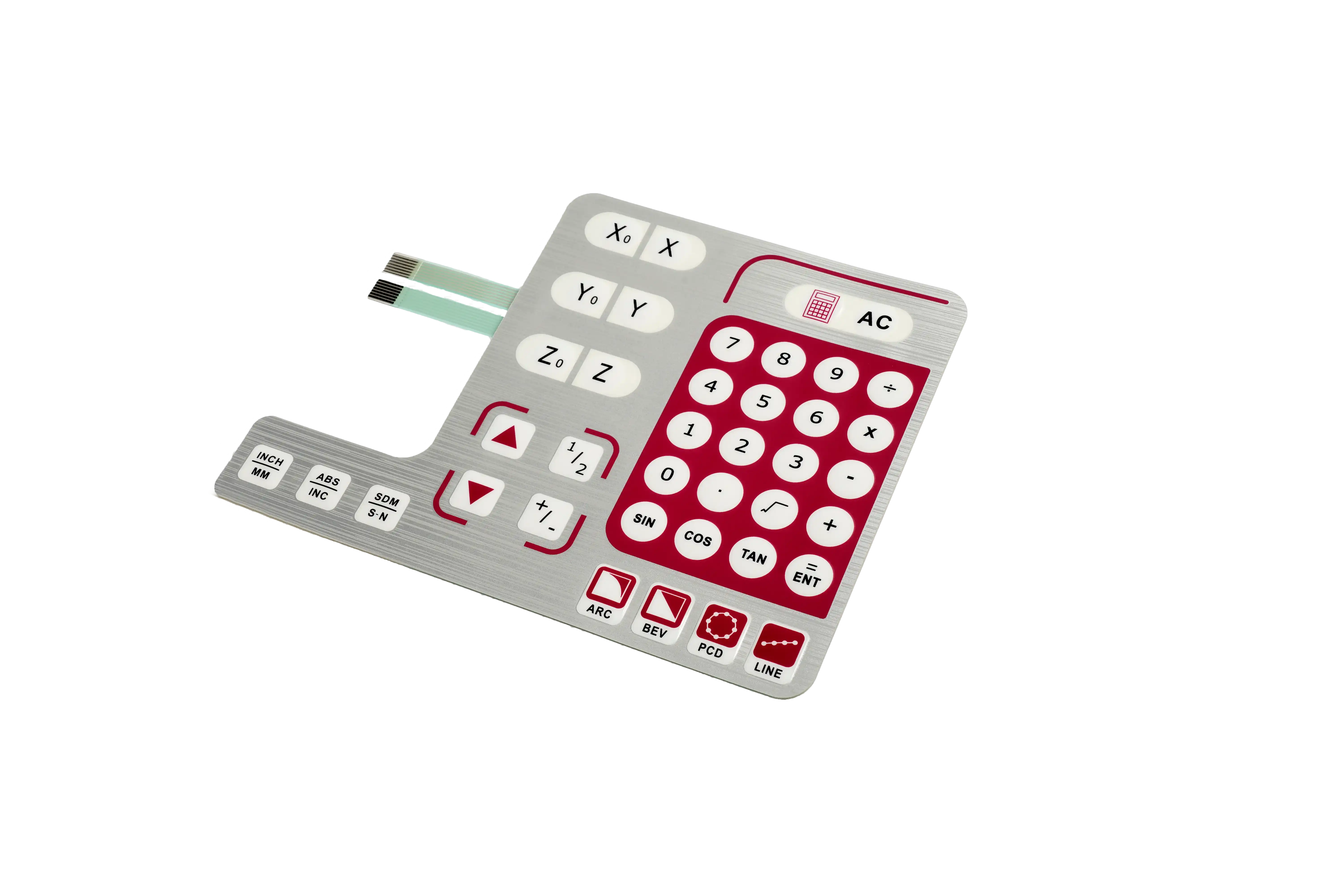
Protect the evidence when the supplier closes
Protect the surviving samples and interface records before authorizing teardown or ordering a look-alike replacement. A supplier closure makes documentation recovery urgent, but it does not establish that the membrane switch caused the equipment fault.
Have qualified equipment personnel isolate the machine under its approved procedure before removal. Photograph the installed panel, tail route, mating connector, labels and enclosure. Record the equipment model, serial-number range, controller revision, firmware revision, symptoms and operating conditions. Keep existing purchasing records, approved artwork, inspection reports and correspondence together under one project revision.
Separate three evidence classes:
| Evidence | Useful for | Must not become |
|---|---|---|
| Failed sample | Locating cracks, corrosion, delamination and worn contact areas | The target for resistance, adhesion or key feel |
| Functioning sample | Comparing key response, fit and electrical behavior | An unprotected teardown specimen |
| Controlled interface information | Defining connector orientation, host signals and accepted functions | An assumption that every equipment revision is identical |
Mark each specimen with its condition and equipment origin. Obtain permission before destructive examination, and preserve the only functioning panel whenever possible. Agree who owns the recovered drawings and who approves the right to reproduce supplied artwork and circuitry.
Build the old-sample shipment and data package
A useful sample package tells the receiving engineer what the panel did, how it connected, and which evidence can be consumed. Send photographs and an inventory before shipping so the receiving team can specify protection and any necessary contamination precautions.
| Include | Record before shipment | Why it matters |
|---|---|---|
| Sample inventory | Individual ID, functioning or failed, quantity, permitted teardown | Prevents destruction of the sole reference |
| Front and rear photographs | Entire outline, labels, windows, damage and a scale in the same plane | Preserves geometry and condition before handling |
| Installed photographs | Bezel, recess, fasteners, tail route and connector access | Shows constraints absent from a loose sample |
| Dimensional record | Width, height, key centers, cutouts, thickness and units | Establishes a measurable reconstruction baseline |
| Tail and connector details | Contact count, pitch, contact side, pin 1, insertion direction and latch | Prevents electrically reversed replacements |
| Functional record | Each legend, intended command, failed keys and allowed combinations | Links the physical interface to host behavior |
| Host information | Board revision, firmware revision, schematic or service pinout when available | Separates panel defects from interface changes |
| Service environment | Cleaning agent, concentration, exposure time, temperature and moisture | Supports material and assembly validation |
| Available files | Dimensioned review PDF, editable geometry, vector artwork and inspection records | Reduces reconstruction ambiguity |
| Project boundary | Required quantities, approval owner, equipment access and retained-sample needs | Defines the quote and validation responsibilities |
Package the panel flat with rigid support and protection that does not press the keys, scratch windows or crease the tail. Protect exposed contacts against contamination; use packaging appropriate to any integrated electronic components. Do not roll the panel or repeatedly operate unsupported tactile keys. Label separated layers and photograph their order if an authorized specialist dismantles a sacrificial sample.
A photograph is not a dimensional drawing. Perspective, shrinkage and a lifted adhesive edge can distort the outline. Use direct measurements and enclosure features as cross-checks, and retain the original images rather than only annotated copies.
Reconstruct the switch definition, not its wear
To reverse-engineer a membrane keypad, rebuild four linked definitions: key geometry, circuit behavior, tail interface and mechanical stack. Every recovered feature should be identified as measured, supported by a controlled record, or proposed for validation.
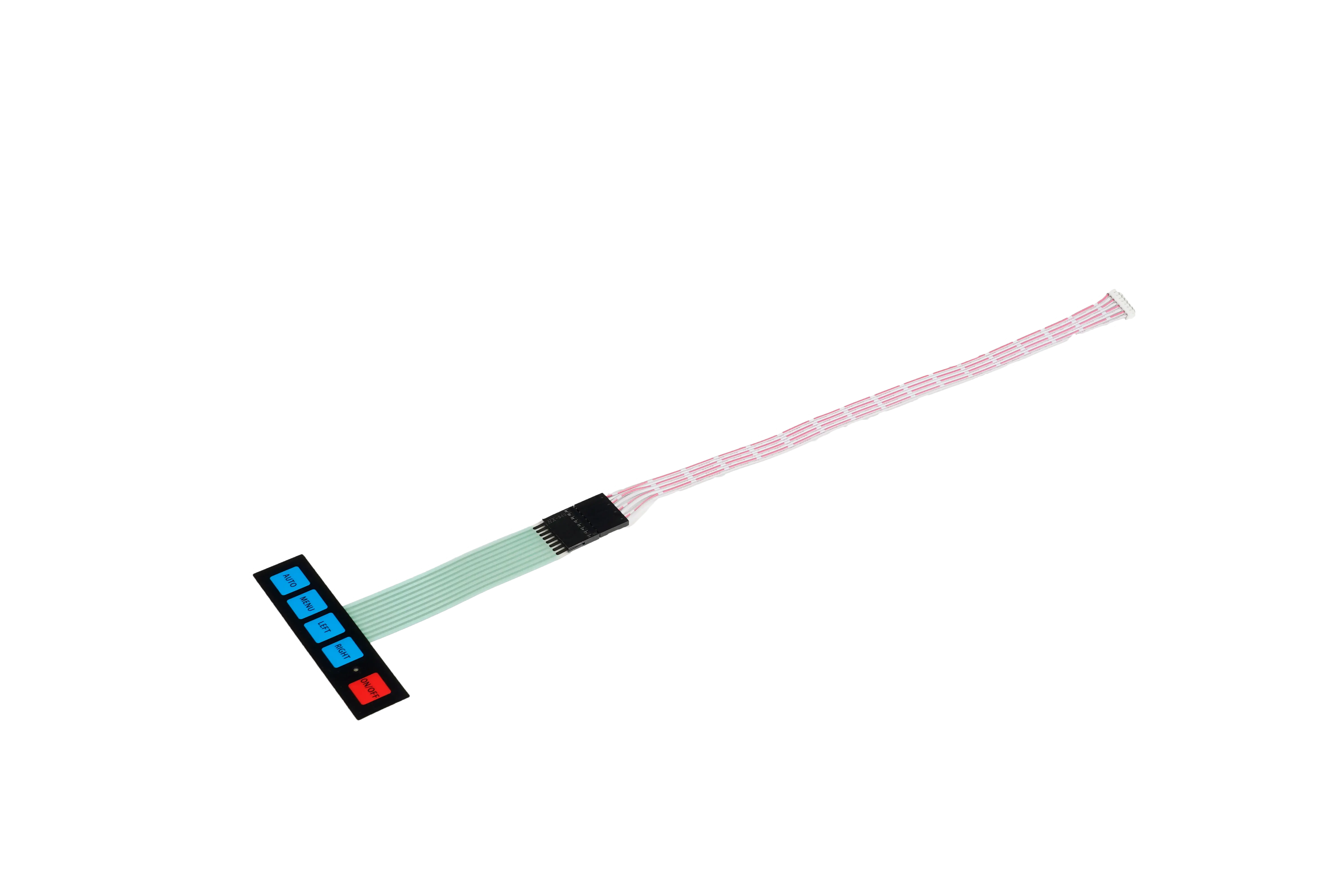
Recover key locations and the circuit map
Establish functional enclosure datums before tracing the outline. Measure key centers, window boundaries, cutouts and tail exit relative to those datums. Preserve the relationship between each printed legend and its actual switching area; attractive graphics do not correct a displaced contact.
For simple contact-based panels, identify all three circuit configurations: common bus, row-column matrix, and mixed common-bus/matrix. A common bus shares a conductor between switches; a matrix connects a row to a column when a key closes. Do not assume the visible arrangement of keys determines the electrical arrangement.
With the panel disconnected from the host and supported, record the released and pressed states for every key at its tail contacts. Use an instrument setting compatible with the identified circuit. LEDs, diodes, resistors or active electronics require their own identification before continuity results can be interpreted. An open reading on a failed trace is damage evidence, not proof that the original design omitted that connection.
Here is an illustrative four-key matrix, not a pinout for an actual panel. The specified view is the exposed-contact side, with tail contacts numbered left to right as 1, 2, 3, 4.
| Key | Row conductor | Column conductor | Closed contact pair |
|---|---|---|---|
| K1 | R1, pin 1 | C1, pin 3 | 1 and 3 |
| K2 | R1, pin 1 | C2, pin 4 | 1 and 4 |
| K3 | R2, pin 2 | C1, pin 3 | 2 and 3 |
| K4 | R2, pin 2 | C2, pin 4 | 2 and 4 |
Keep this electrical map separate from the command table. The host determines whether K1 means a menu selection, an increment or another function.
Define the complete tail interface
Record tail exit position, usable length, width, pitch, exposed-contact dimensions, stiffener thickness, contact finish, contact side, insertion depth and bend restrictions. Identify the mating connector and its numbering convention from controlled information. Mechanical fit alone does not establish electrical compatibility.
Do not use a convenient new pin order on an unchanged host. A proposed connector substitute must match the complete interface or become a documented adaptation with separate approval.
Rebuild tactile behavior and the adhesive stack
Distinguish non-tactile contacts, metal-dome tactile contacts, and formed-polyester tactile contacts; a panel may mix constructions. Measure force and travel on supported samples, not a loose panel held in the air. Compare surviving keys cautiously because use and aging may have changed their response.
Record every film, circuit, spacer, dome carrier, shield and adhesive layer, including keep-outs and air-displacement paths. Specify the mounting substrate and surface preparation. Residual glue thickness is not necessarily the original adhesive specification. A substitute stack must preserve clearance, key return, bonding area and the intended sealing boundary after installation.
Identify what the old panel cannot prove
An old panel can reveal its present condition, but it cannot establish the complete original specification or the required life of its replacement. Convert these gaps into explicit design inputs and validation tasks rather than silently copying the specimen.
| Old-sample observation | What it cannot establish alone | Required basis for approval |
|---|---|---|
| Film appearance and thickness | Exact resin grade, coating or chemical resistance | Material identification or qualified replacement specification |
| Remaining adhesive | Original chemistry, shelf history or bond strength | Selected adhesive data and tests on the actual substrate |
| Worn tactile response | Original force tolerance or remaining cycle life | Approved force-displacement envelope and endurance requirement |
| A working key on one machine | Compatibility with every board and firmware revision | Equipment revision matrix and host verification |
| Intact perimeter | Equipment ingress or environmental compliance | Defined installed boundary and applicable qualification evidence |
| Matching graphics | Design ownership or permission to reproduce marks | Buyer-authorized artwork and reproduction approval |
A replacement may use a different material or process while preserving the required interface. That is a controlled substitution, not proof that the original construction has been recovered exactly.
Diagnose wrong keys without trial connections
Wrong commands after replacement call for a pin-map and orientation check before any further host connection. Stop using the equipment if an input produces an unintended action. Disconnect and isolate it under the OEM procedure; never reverse a live tail to see whether the symptoms improve.
Compare the approved key-to-contact table with a disconnected measurement of the replacement. Then compare the tail's contact-side view with the mating connector's documented view. A photograph taken from the opposite side reverses apparent left and right.
In the four-contact example, a complete numbering reversal maps 1 to 4, 2 to 3, 3 to 2, and 4 to 1. K1's pair can therefore be interpreted as K4's pair, while some other pairs remain unchanged. A few working keys do not prove that the tail orientation is correct.
| Symptom | First distinction to make | Next evidence |
|---|---|---|
| Consistently wrong single-key commands | Pin order, mirrored view or legend-to-contact mismatch | Disconnected key map against connector drawing |
| A whole group of dead keys | Shared row, column, common conductor or connector fault | Continuity along the shared path and contact engagement |
| Results change when the tail moves | Cracked conductor, routing stress or poor mating contact | Supported inspection and routing test within approved bend limits |
| One press creates repeated commands | Contact instability, mechanical return or host timing | Electrical transition record and host event record |
| Extra commands appear only during combinations | Scan ambiguity, unintended shorts or unsupported combinations | Circuit topology plus the permitted host key sequence |
Do not label every multi-key fault “ghosting.” Scan method and circuitry determine which combinations are distinguishable; contact bounce and a permanent short are different mechanisms. Recreating the membrane alone does not authorize firmware changes.
Choose the replacement route by compatibility
A custom membrane switch replacement is appropriate when the required interface can be defined and verified. Select the route from the evidence, not from a promise that any old panel can be copied.
| Route | Use when | Release condition |
|---|---|---|
| Direct reconstruction | Geometry and host interface are recoverable | New drawings and installed samples meet the unchanged requirements |
| Controlled material or process substitution | An original material is unavailable, but the interface can stay fixed | Differences are documented and affected performance is requalified |
| Controlled interface adaptation | A connector or tail change cannot be avoided | OEM approves the adaptation and its equipment compatibility |
| Stop membrane-only release | Host behavior, damaged circuitry or safety requirements remain unresolved | Resolve the equipment-level problem before promising interchangeability |
For discontinued control panel keypad replacement, display electronics, controller faults and enclosure redesign remain separate scopes. Do not purchase a membrane-only component as though it included a new complete control system.
Validate electrical margin and installed performance
A replacement passes only when measured electrical behavior and installed operation meet the approved requirements. A continuity beep does not measure enough to establish input margin or distinguish a usable contact from an unstable one.
For identified passive printed contacts, begin with a ≤100 Ω closed-loop resistance design target. Measure the entire closed path through the specified mating connection with the panel supported and a recorded normal actuation force. Record test current or voltage, instrument, fixture and temperature. The test voltage for released-state isolation must suit the identified circuit; never apply an insulation tester to connected host electronics. This is a starting target, not a universal rating or a JASPER performance guarantee; a stricter host limit governs. A higher-resistance existing design needs an explicit margin assessment rather than automatic rejection.
Check the host input, not just resistance
An illustrative static pull-up circuit shows why the host matters. Assume a 3.3 V supply, a 10 kΩ pull-up, a 100 Ω closed path to an ideal low output, and a maximum guaranteed-low threshold of 0.8 V. These are example inputs, not recovered equipment specifications.
V_input = V_supply × R_closed / (R_pullup + R_closed)
The result is 3.3 × 100 / (10,000 + 100) ≈ 0.033 V. Increasing the closed path to 1,000 Ω gives 0.300 V. Both are below the assumed static threshold, but this calculation excludes leakage, resistor tolerance, output-drive resistance, noise and scan settling. It does not prove that either resistance is acceptable on the real controller. Evaluate the released state and timing as well.
Use a traceable sample record
As an initial project screening plan, use three independently assembled prototypes, checking 100 actuations per key on each prototype at 23 ± 2 °C, with the intended support, connector and routing. Require 100% key coverage and zero wrong, missed or extra commands in the agreed sequence. This proposed screen is not endurance qualification or proof of a lifetime failure rate.
| Check | Record and method | Approval basis |
|---|---|---|
| Key identity and combinations | Key ID, contact pair, host event, press/release sequence | Every required function correct; only specified combinations accepted |
| Closed and released circuits | Resistance in Ω or MΩ, source setting, force, fixture and temperature | Released electrical limits and adequate input margin |
| Switching behavior | Transition and host-event timing in ms; repeat and release behavior | Compatibility with the unchanged host's scan and debounce behavior |
| Mechanical fit | Dimensions in mm, datum references, installed thickness and clearances | Released tolerances; no preload, pinching or interference |
| Tactile response | Force in N and travel in mm, supported assembly and actuator method | Approved force-displacement envelope and reliable return |
| Bonding and environment | Substrate, preparation, dwell, exposure and post-test function | Application-specific bond and environmental criteria |
After passive checks pass, qualified personnel should perform host tests in an OEM-approved fixture or diagnostic condition that prevents hazardous machine actions without defeating safety functions. Exercise every key, allowed combination, hold, release and intended repeat behavior across the listed equipment revisions.
Install the panel using the approved stack-specific method. Do not roll it into place like a label or apply uncontrolled pressure across domes, windows or components. Repeat functional checks after installation and after the agreed environmental exposures. Room-temperature screening cannot replace qualification for the actual service environment.
Freeze the revision before approving supply
Freeze the reconstructed definition only after sample discrepancies are resolved and the OEM accepts the installed result. Keep the failed specimen, functioning reference and approved new sample separately identified; none should silently replace another as the production master.
The release package should contain dimensioned mechanical drawings, artwork, layer and material definitions, the key-to-pin table, connector-view drawing, electrical limits, inspection methods, installation requirements and approved sample records. Every record should identify the sample ID, drawing revision, test date, operator, instrument or fixture ID, result and disposition. Identify the equipment and firmware revisions covered by the approval.
Purchasing should name ownership and access rights for drawings, production tooling and test fixtures. Require lot traceability and an approval path for changes to materials, contact construction, tail geometry, adhesives or manufacturing processes. Agree which changes require renewed equipment testing.
Separate reconstruction charges, prototype work, qualification work and production pricing in the quote. The switch supplier is responsible for the agreed component deliverables; the equipment OEM retains responsibility for host compatibility and equipment-level approval. A successful sample is not a substitute for repeat-order controls.
Frequently asked questions
Can a membrane switch be replaced without original drawings?
Yes, when the mechanical and electrical requirements can be recovered from samples and controlled equipment information. The supplier must produce a new documented definition rather than simply reproduce the outline. Approval still requires correct key mapping, tail compatibility, installed fit and the agreed performance checks on the intended host revisions.
Is a failed sample enough to start reverse engineering?
A failed sample is enough to start an assessment, but it is not always enough to release a replacement. Broken traces and worn keys can hide original behavior. Include a functioning reference or controlled host information whenever available, and explicitly authorize which specimen may be dismantled or consumed during analysis.
What should be saved when the original supplier closes?
Save the latest approved files, purchasing history, sample records, inspection reports, connector information and surviving panels before they become inaccessible. Record the equipment and firmware revisions associated with each panel. Protect the only functioning sample, and establish who can approve reconstruction, destructive inspection and use of the recovered design files.
Why do replacement keys activate the wrong functions?
Wrong functions can result from a reversed connector view, changed pin order, incorrect circuit mapping or a mismatch between legends and contact locations. Disconnect the replacement and compare every key-to-contact pair with the approved interface table. Do not troubleshoot by reversing a powered tail or changing firmware to conceal an unverified wiring error.
Does matching the tail pitch guarantee compatibility?
No. Matching pitch leaves contact count, contact side, numbering, exposed length, insertion depth, thickness, stiffener, contact finish and latch engagement unresolved. Tail routing can also stress the connection after assembly. Verify the complete mating interface and its electrical map before connecting the replacement to the original equipment.
Can the replacement use different films or adhesives?
Yes, provided the substitution preserves the required interface and passes the affected validation. A similar thickness or appearance does not prove equivalent bonding, chemical resistance, tactile response or sealing. Document the new material definition and test it on the actual mounting substrate with the intended preparation, installation and service exposures.
What should a first compatibility sample prove?
It should prove every required key function, correct electrical mapping, host input margin, connector fit, installed clearance and reliable key return. Record the test conditions and applicable equipment revisions. A short functional screen does not establish endurance, environmental qualification or equipment compliance; those need their own defined methods and acceptance criteria.
What happens if the original connector is obsolete too?
Treat the connector as an interface problem, not permission to change the pinout without approval. First determine whether a replacement can preserve the full mating definition. An adapter, altered tail or host-side change requires documented OEM approval and validation. Where that cannot be achieved, do not describe the new panel as directly interchangeable.
Start with a defined replacement package
JASPER's custom membrane switches provide the product path for reviewing the reconstructed circuit, tail, stack and assembly requirements.
Use Send Drawing to describe the project and arrange submission of the old panel's front and rear photographs, dimensions, interface photographs and available sample condition. Include the host revision and teardown permission. The first decision is what can be preserved and verified—not whether the new graphics look close enough.
Bring the drawing, stack and operating conditions
JASPER engineering will review the interfaces, open risks and evidence required for a production quote.