
A microwave oven membrane keypad should be specified as part of the installed control system, not as artwork attached late in development. It fits OEM appliances that need a low-profile, graphic-rich pressure interface, provided the overlay, circuit, key feel, adhesive, tail exit, housing seal, controller logic, and test plan are designed together. The critical inputs are key layout, steam and cleaner exposure, local panel temperature, display and backlight geometry, tail routing, enclosure construction, regulatory market, and production-intent sample approval. This is a custom OEM design guide, not consumer replacement or repair advice.
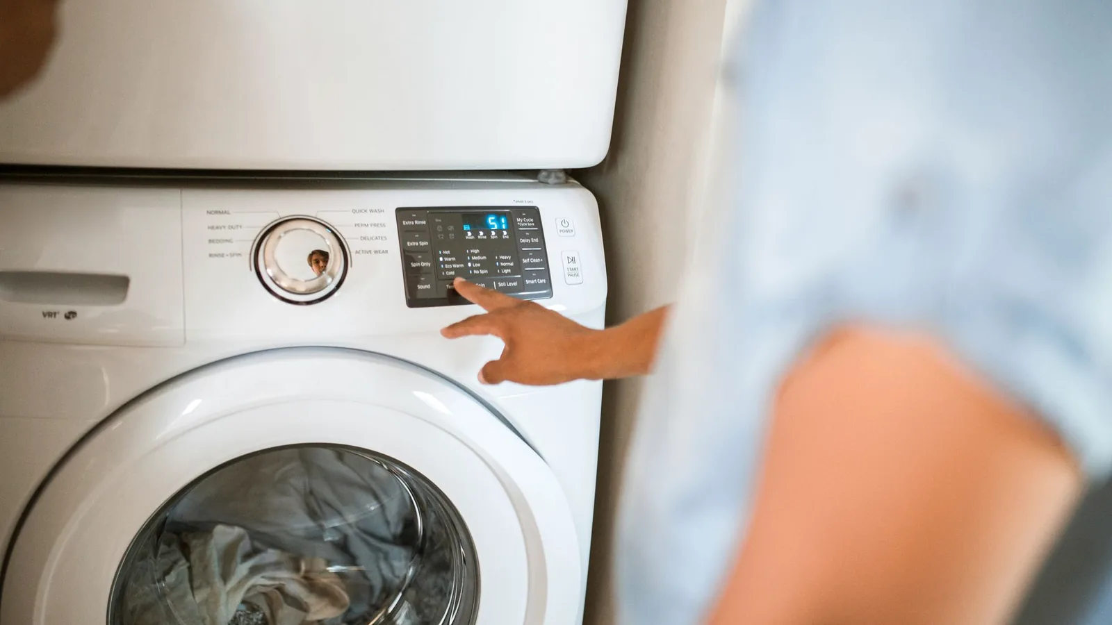
Quick Decision Table for Appliance Control Panels
The construction follows the installed environment; an isolated “waterproof keypad” claim does not resolve perimeter, display, connector, or tail interfaces.
| Project condition | Preferred design direction | What must be verified on the appliance |
|---|---|---|
| Routine wiping, occasional splash, no direct steam plume | Hardcoated overlay, continuous perimeter bond, protected tail exit | Cleaner compatibility, edge lift, wet-key operation, housing drainage |
| Repeated steam or condensation | PET-focused overlay evaluation, minimized edge exposure, sealed tail transition, corrosion-aware circuit layout | Condensation path, insulation resistance under bias, post-exposure function |
| Elevated temperature near an oven cavity or vent | Grade-specific film, ink, spacer, dome, and adhesive selection | Measured control-panel temperature map, hot-state key feel, bond creep, legend stability |
| Nighttime use or hidden legends | LED or light-guide architecture with controlled windows and opaque masking | Luminance uniformity, color, light leak, hot spots, day/night contrast |
| Tight controller location or moving assembly path | Tail and connector designed from enclosure CAD; copper FPC considered for demanding bends | Assembly insertion, bend and strain, connector latch access, service movement |
| Safety-related command | Keypad used only as an input to the safety architecture, with independent protection where required | Fault response, stuck-key behavior, firmware diagnostics, end-product compliance |
Membrane switches can combine graphics, contacts, windows, and a flexible tail. The construction becomes a liability if steam reaches silver traces or an enclosure rib loads a dome continuously.
How a Microwave Oven Membrane Keypad Works in the Installed Appliance
A membrane keypad is a momentary interface made from laminated flexible layers. Finger pressure closes conductive surfaces; the controller reads a row-column matrix or dedicated line, applies debounce and command logic, then provides visual or audible feedback.
For design foundations, use the Membrane Switch Design Guide for OEM Engineers. How Membrane Switches Work: Layers and Signal Path covers contact closure.
A typical appliance stack contains these functional layers:
- Graphic overlay: Second-surface printed PET or polycarbonate carries legends, finish, key boundaries, and windows.
- Overlay adhesive or dome retainer: Bonds the face layer and can locate metal domes.
- Actuation element: The design may use a metal dome, formed polyester dome, or a flat non-tactile contact.
- Spacer: Die-cut openings keep the conductive surfaces apart until a key is pressed. One named example, 3M 7956MWS, uses a 2.0 mil PET carrier with 2.0 mil acrylic adhesive on each side; that construction is an example, not a universal specification.
- Circuit: Screen-printed silver on PET suits many low-current matrices; copper FPC or PCB support serves different routing or component needs.
- Rear adhesive and seal geometry: Fixes the switch to the bezel and contributes to, but does not complete, the environmental barrier.
- Tail, stiffener, and termination: Carries the matrix to the documented controller connection.
Molex describes appliance membrane controls as pressure-contact interfaces with optional embedded LEDs and no openings around traditional buttons. The display, perimeter, interior air spaces, and tail remain design boundaries.
A Microwave Oven Membrane Keypad Layout Should Reflect Use Frequency and Error Consequence
Key layout is an electrical and safety input. Place frequent, low-consequence commands naturally. Separate start, cancel, power, and time controls so an imprecise press cannot produce a plausible wrong instruction. Shape, spacing, color, and light should reinforce that grouping.
Create the key map before routing the circuit. Each visible legend needs a controlled relationship to its active contact, dome center, spacer opening, and controller scan code. A 12-key microwave matrix, for example, is not defined by the key count alone. The drawing must identify the row-column assignment, connector pinout, inactive combinations, simultaneous-press behavior, debounce rules, long-press behavior, stuck-key response, and the feedback the user receives after a valid input.
Tactile feedback should follow the usage model:
| Interface choice | Good fit | Main trade-off | Approval focus |
|---|---|---|---|
| Metal dome | Distinct snap response and compact keys | Dome force and sound vary with stack and support | Force profile, centering, sound, hot/cold feel |
| Formed PET dome | Integrated, quieter tactile response | Feel is sensitive to film, geometry, and temperature | Return behavior and life on the final overlay |
| Flat non-tactile contact | Simple sealed face with controller feedback | No mechanical confirmation | Audible/visual response and false-press rejection |
| Silicone-rubber keypad | Deeper travel, larger key motion, sculpted keys | Thicker assembly and different sealing/graphic architecture | Compression set, legends, bezel openings, contamination paths |
| Capacitive touch | Unbroken rigid fascia and styling flexibility | Wet fingers, splashes, gloves, firmware, and feedback require careful tuning | Water behavior, EMC, thresholds, fault handling, usability |
Do not use the membrane keypad as the sole safety interlock. Faults must fail safely. If a normally closed diagnostic input is needed elsewhere, review the Normally Closed Membrane Switch Design Guide, then keep that function distinct from the appliance's independent protections.
Moisture and Steam Control Depend on the Perimeter, Tail Exit, and Housing
Steam moves through small gaps, condenses on cooler surfaces, and can remain inside a layered assembly. Follow the path from cavity and vent to bezel seam, display window, fasteners, keypad edge, tail slot, connector, and controller PCB.
Start with the housing. Provide a flat bonding land without sink, texture peaks, overspray, release agent, ribs, or fastener distortion. Keep the keypad edge out of direct condensate paths. Close the flex-exit thickness step with a defined tail filler or gasket. If pressure equalization is needed, document a vent path away from the wet edge. Hidden vents can become moisture channels.
An IP or NEMA claim belongs to the tested assembly. IEC 60529 [5] defines protection provided by enclosures. NEMA 250 [6] addresses installed enclosures and excludes internal condensation and contaminants entering through unsealed openings. An unattached “IP65 keypad” does not prove appliance-panel ingress performance. Test the installed assembly. Include the actual display, tail exit, gasket, connector opening, fasteners, and process.
Moisture also creates an electrical failure path. ASTM F1996 links moisture plus DC potential to silver migration, reduced insulation resistance, and shorts. A Samsung Electronics study traced multi-key operation to Ag-ion migration after moisture entered a silver-paste membrane under heat and humidity. Control contamination, trace geometry, dielectric coverage, venting, edge and tail seals, bias, and post-exposure insulation.
Heat, Cleaners, Overlay Film, and Adhesive Must Be Qualified as One Stack
Select materials from a measured panel environment, not the oven setpoint. Measure the real bezel. Include worst normal and relevant abnormal modes, cavity and exhaust heat, displays, LEDs, controls, and power components. Record bond-line temperature, gradient, duration, cycling, humidity, and mechanical load.
PET is often favored where flexing and chemical exposure dominate; polycarbonate provides useful forming, print, and optical options. Grade selection is decisive. MacDermid Alpha Autotex XE is a hardcoated PET for membrane panels exposed to humidity, UV, and temperature variation, with 150 µm, 200 µm, and selected 280 µm grades. Covestro Makrofol polycarbonate grades address transparency, light management, abrasion, weathering, and heat. Neither supplier qualifies the finished appliance panel.
Adhesive performance is equally substrate-specific. The September 2025 3M 467MP sheet reports, after 72 hours of dwell and ASTM D3330 testing at 23°C, 90-degree peel values of 2.4 N/cm on ABS and 7.8 N/cm on polycarbonate at 300 mm/min. That difference is a warning against copying one peel value across bezel plastics. The same sheet's short-term 204°C result used a 500 g load for 60 minutes on a 6.5 cm² sample; it is not permission to rate an appliance keypad for 204°C.
Build a cleaner matrix from service instructions and foreseeable misuse. Record formulation or active chemistry, concentration, application, dwell, wipe material, temperature, and repetitions. Inspect gloss, haze, color, legends, windows, embossing, edge lift, adhesive ooze, key feel, function, and insulation resistance. “Resistant to household cleaners” is not an approval criterion.
Backlighting and Display Windows Need Optical and Mechanical Registration
Control both off-state and energized appearance. Define ambient-light range, viewing angle, icon color, luminance, uniformity, light leakage, display contrast, and acceptable dead-front visibility. A dark fascia that looks clean in a studio can lose contrast under kitchen task lighting.
For discrete indicators, locate LEDs against printed windows and control distance, mask opacity, diffusion, and reflections. A light guide can serve several keys, but its extraction pattern, coupling, compression, and spacer must match the LED. Keep adhesive, embossing, and color boundaries out of critical viewing apertures unless modeled into the optics.
Control every datum. Reference bezel to keypad, keypad to graphic, graphic to window, window to display, and graphic to active key. Approve day, dim, and dark conditions on production-intent hardware. Measured optical criteria control acceptance; photographs document it.
Circuit and Tail Routing Must Be Designed from the Controller Backward
Start at the connector. Lock pin count, pitch, contact side, insertion direction, exposed-conductor length, stiffener, latch access, and keep-out zone. Route the tail in enclosure CAD without sharp edges, pinches, unsupported folds, adhesive traps, or a bend at the stiffener.
Printed-silver PET is economical for low-current switch matrices when the route, spacing, environment, and connector are compatible with the process. Copper FPC is worth evaluating when the geometry demands finer routing, repeated dynamic movement, different connector features, components, shielding, or electrical behavior that the printed circuit cannot meet comfortably. A rigid or PCB-backed membrane panel can support LEDs, connectors, or local electronics, but it changes thickness, fastening, sealing, and service loads.
The electrical drawing should state the schematic, pinout, contact assignment, switching limits, open/closed acceptance criteria, insulation, crossover construction, ESD/EMI provisions, and shield termination. “Same as sample” is not a circuit definition. Lamination can hide a pinout revision.
Application-Risk Matrix for Appliance Membrane Switches
The risk review should connect each physical path to an observable failure and an owner. Generic durability testing misses interface failures when the keypad, bezel, controller, and assembly process are qualified separately.
| Hazard or input | Failure path | Likely symptom | Detection method | Design or process control | Owner |
|---|---|---|---|---|---|
| Steam/condensation | Perimeter, window, vent, or tail path wets circuit | Leakage, ghost key, multiple keys, corrosion | Biased humidity/condensation exposure; insulation and functional checks | Continuous seal, controlled vent, dielectric, clean assembly | Mechanical + electrical + quality |
| Heat gradient | Film, ink, dome, or adhesive changes under local heat | Edge lift, haze, shifted feel, stuck key | Installed temperature mapping and hot-state operation | Grade-specific stack and thermal separation | Mechanical + materials |
| Cleaner exposure | Chemistry attacks hardcoat, ink, window, or adhesive | Glossing, legend loss, cracking, delamination | Formulation-specific repeated wipe test | Approved cleaner list and material compatibility | Industrial design + quality |
| Misregistration | Datum stack shifts graphic, dome, contact, LED, or display | Missed press, off-center feel, light leak | Overlay measurement and illuminated fixture check | Shared datums, controlled tolerances, vision inspection | Supplier + manufacturing |
| Tail strain | Flex is creased, pinched, or pulled at connector | Intermittent or open circuit | Assembly simulation, continuity while manipulated | Keep-outs, strain relief, protected exit, work instruction | Mechanical + manufacturing |
| Controller fault handling | Stuck or simultaneous key is accepted as valid | Unintended command or locked interface | Fault injection and firmware-state test | Debounce, timeout, invalid-combination logic, safe response | Firmware + safety |
| Housing distortion | Fastener or rib preloads active key or breaks bond | Continuous actuation, hard key, edge lift | Worst-tolerance housing build and torque check | Flat land, support plan, controlled fastener load | Mechanical + supplier quality |
Regulatory Inputs Apply to the Finished Appliance, Not the Keypad Alone
Start with product category and destination market. Component evidence supports the file; it does not certify the oven.
| Authority or document | Verified scope or requirement | Keypad-design implication |
|---|---|---|
| International Electrotechnical Commission — IEC 60335-2-25:2024 | Household and similar microwave ovens up to 250 V, including DC-supplied appliances; used with IEC 60335-1 | Map keypad inputs and faults into the complete appliance safety assessment |
| UL Standards & Engagement — UL 923 | U.S. household and commercial microwave cooking appliances in ordinary locations up to 600 V | Confirm component evidence with the certification body; do not claim keypad-level UL 923 compliance |
| U.S. Food and Drug Administration — 21 CFR 1030.10 | FDA [3] summarizes a 5 mW/cm² lifetime leakage limit at about 2 inches and requires two door interlocks plus monitoring | “Start” and “Add Time” inputs cannot replace independent door interlocks |
| Federal Communications Commission — 47 CFR 18.203 | Consumer ISM equipment requires authorization before use or marketing | Treat FCC authorization as an end-product workstream |
| International Electrotechnical Commission — IEC 60529 | IP Code applies to protection provided by enclosures | Test the installed bezel, openings, seal, and assembly |
| National Electrical Manufacturers Association — NEMA 250 | Addresses installed electrical enclosures; scope does not cover internal condensation | Define condensation separately from an enclosure Type target |
| ASTM International — ASTM F1996-06 | Historical method for silver migration under moisture and DC potential | Confirm current status and agreed conditions before including it in a qualification protocol |
Assign every safety, EMC, radiation, flammability, accessibility, ingress, chemical, and marking requirement to the appliance, enclosure, control assembly, or component. The certification body decides acceptable evidence. The UL and CSA Requirements for Membrane Switch Assemblies guide can organize component records, but an internal page is not proof.
Production-Intent Samples Must Pass Form, Fit, Function, and Environment
A visual golden sample is not enough. Appearance is not approval. Use testing and validation planning to define methods, sample sizes, conditions, measurements, and criteria. Use prototyping and sample approval to separate an appearance model from a released production-intent stack.
Set criteria before testing. The approval sequence should cover:
- Drawing review: Datums, stack, materials, artwork, windows, embossing, dome, circuit, pinout, tail, connector, adhesive, labels, and inspection notes.
- Incoming inspection: Identity, revision, dimensions, print, window, surface defects, tail contacts, connector/stiffener, and electrical function.
- Installed fit: Bonding land, alignment, adhesive wet-out, bezel gaps, tail path, display registration, fastener effects, and assembly work instruction.
- User interface: Key targeting, force profile, feedback, audible response, display response, gloves or wet fingers if relevant, and invalid-key behavior.
- Environment: Product-specific heat, humidity, condensation, splash, cleaner, grease, cycling, storage, transport, and actuation, with pre- and post-conditioning measurements.
- Fault response: Open line, shorted line, stuck key, simultaneous keys, connector partial insertion, insulation loss, and recovery after power interruption.
- Release record: Approved sample, controlled drawing, bill of materials or approved equivalents, test report, deviation list, packaging, and change-notification rules.
When a Membrane Switch Is Not the Right Appliance Interface
Choose another architecture for long travel, replaceable switches, sculpted keys, heavy-glove use, or a rigid-glass model. Silicone rubber can provide deeper travel; discrete switches support serviceable high-force controls. Capacitive touch can create an unbroken fascia, but splash-induced capacitance changes and firmware complexity require thorough testing.
It is also a poor choice without a stable bonding land, when the tail must move beyond the circuit's capability, or when no available stack can pass the required chemical and thermal tests.
Project-Input Checklist for Drawing Review and Sample Approval
Send a controlled package rather than a screenshot. The minimum project inputs are:
- Appliance type, destination markets, applicable end-product standards, and certification-body constraints.
- Bezel CAD, bonding-land material and texture, tolerances, vents, drainage, display, fasteners, and tail path.
- Key layout, legend artwork, language variants, color references, finish, embossing, tactile choice, and feedback behavior.
- Circuit schematic or matrix, pinout, connector details, switching limits, insulation criteria, controller scan logic, and fault response.
- Measured environment: local temperature, humidity, condensation, steam direction, splash, grease, cleaners, UV, storage, and use profile.
- Window and lighting requirements: display type, visible area, dead-front state, LEDs, color, luminance, uniformity, ambient light, and viewing angle.
- Validation plan with conditions, sample size, measurements, acceptance criteria, sequence, and post-exposure checks.
- Annual volume, pilot quantity, packaging constraints, target assembly process, approved material restrictions, and change-control requirements.
- Sample approval owners for engineering, industrial design, firmware, quality, regulatory, manufacturing, and procurement.
Use these inputs to send drawings for engineering review. Include the key layout, circuit requirements, annual volume, and operating environment so the supplier can review the real assembly rather than quote an undefined overlay. When the drawing and validation boundary are ready, request an engineering quote.
Frequently Asked Questions
What is a microwave oven membrane keypad?
A microwave oven membrane keypad is a laminated, low-profile switch interface that closes momentary electrical contacts when a printed key area is pressed. In an OEM design, it includes the graphic overlay, actuation structure, spacer, circuit, mounting adhesive, tail, and termination, all matched to the appliance bezel and controller.
Is a membrane switch on a microwave the same as a replacement touchpad?
No. A replacement touchpad is a model-specific service part. This guide addresses a custom OEM membrane switch on a microwave before production, including circuit definition, materials, enclosure sealing, controller behavior, regulatory inputs, and validation. Model numbers and brand compatibility do not define a new control-panel design.
Can a microwave membrane switch be rated IP65 by itself?
An isolated keypad claim does not establish the installed appliance rating. IEC 60529 applies IP codes to enclosures, and the real ingress paths include the bonded perimeter, display, vent, tail exit, fasteners, and housing seams. Test the production-intent keypad on the representative bezel with every opening and assembly process included.
Should an appliance keypad use PET or polycarbonate?
Choose a specific film grade after defining temperature, humidity, cleaner, flex, embossing, print, window, and lighting requirements. Hardcoated PET is often evaluated for flex and chemical exposure; polycarbonate offers useful forming and optical grades. Supplier family descriptions are not final-assembly evidence, so validate the printed and bonded stack.
How should a membrane-switch tail be routed?
Route the tail from the controller connector through enclosure CAD. Specify contact side, pitch, stiffener, exposed conductors, insertion direction, strain relief, keep-outs, and tail exit seal. Avoid sharp edges, pinches, fasteners, unsupported folds, and a bend at the stiffener transition. Verify routing during the actual assembly sequence.
What causes ghost keys or multiple key activation after steam exposure?
Moisture can lower insulation resistance, create leakage paths, contaminate contacts, or enable electrochemical migration between biased silver traces. Diagnose the complete path: perimeter, window, vent, tail exit, connector, dielectric coverage, circuit spacing, and controller thresholds. Validation should combine biased environmental exposure with insulation and functional checks.
What should be approved on a production-intent keypad sample?
Approve the controlled drawing, materials, graphics, windows, key feel, circuit and pinout, tail and connector, installed fit, lighting, electrical criteria, user-interface behavior, environmental performance, fault response, packaging, and change-control rules. Record quantitative acceptance criteria; a signed visual sample alone cannot control hidden electrical or material revisions.
Does the keypad control the microwave door safety interlocks?
It should not replace them. FDA requirements place independent door interlocks and monitoring in the finished microwave's radiation-safety architecture. The keypad can send cooking commands to the controller, but safety-related interlocks, fault responses, and compliance evidence must remain independent and be assessed at end-product level.
References
- International Electrotechnical Commission, IEC 60335-2-25:2024 — Particular requirements for microwave ovens, published July 11, 2024.
- UL Standards & Engagement, UL 923 — Microwave Cooking Appliances, seventh edition, revised May 2, 2024.
- U.S. Food and Drug Administration, Microwave Ovens, accessed August 24, 2026.
- Electronic Code of Federal Regulations, 47 CFR §18.203 — Equipment authorization, accessed August 24, 2026.
- International Electrotechnical Commission, IEC 60529 — Degrees of protection provided by enclosures, consolidated edition 2.2.
- National Electrical Manufacturers Association, NEMA 250-2018 Contents and Scope.
- 3M, Adhesive Transfer Tape 467MP Technical Data Sheet, September 2025.
- 3M, Membrane Switch Spacer 7956MWS, accessed August 24, 2026.
- MacDermid Alpha Electronics Solutions, Autotex XE Technical Data Sheet CPI-00026/6, January 4, 2023.
- Molex, Upgrading HMI Solutions on Home Appliance Products, accessed August 24, 2026.
- ASTM International, ASTM F1996-06 — Silver Migration for Membrane Switch Circuitry, historical standard page accessed August 24, 2026.
- J. S. Ha, W. S. Choi, and S. D. Park, “Improving Quality of Keyboard by Analyzing the Migration of Ag Ions”, Reliability Engineering Association of Japan, 2001.
- Covestro, Makrofol Thermoplastic Polycarbonate Films, accessed August 24, 2026.
Bring the drawing, stack and operating conditions
JASPER engineering will review the interfaces, open risks and evidence required for a production quote.