
There is no responsible universal minimum for a small membrane button. Compact geometry must fit the operator target, tactile element, emboss, routing, vent path, and registration stack inside one controlled pitch, then pass production-intent testing before tooling.
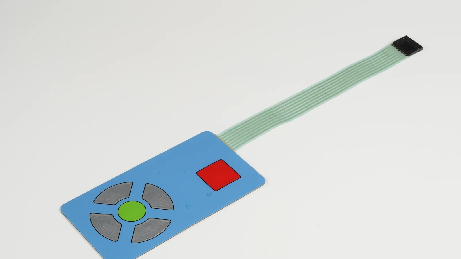
A compact membrane button switch can place several controls in a small panel, but printed artwork is only the visible layer. The usable geometry also includes the finger or glove target, metal dome or printed contact, spacer aperture, overlay flex, conductive routing, tail exit, display openings, and the tolerances of every aligned layer. This guide is for OEM mechanical, electrical, industrial-design, and sourcing teams deciding whether a compact membrane keypad is ready for quotation and tooling.
1. Why Small-Key Geometry Fails Late
Small-key layouts fail late when the enclosure, artwork, circuit, and operator assumptions are frozen in separate files. A legend may fit in the graphic file while the selected tactile element cannot fit under it. An emboss may clear the neighboring key in nominal CAD but move across the dome after print, cut, emboss, and lamination tolerances accumulate. A circuit route may fit before a status LED, window, or tail keep-out is added. None of those problems is solved by making the printed icon smaller.
The operator is part of the geometry. ISO 9241-210:2019 describes human-centred design for interactive systems, but it does not provide a universal membrane-button size. The OEM still has to define the actual user, glove, posture, viewing angle, press frequency, key hierarchy, and consequence of an adjacent actuation. A seldom-used setup key and a high-frequency Start control should not inherit the same risk simply because the grid looks orderly.
The mechanical stack is equally specific. A tactile key must coordinate the metal dome membrane switch, retainer, spacer aperture, overlay material, emboss, support plane, and actuation direction. A non-tactile key removes the dome footprint but still needs contact geometry, spacer travel, venting, and deliberate feedback from the host interface. The circuit then needs a route between active areas without violating the selected printing or flexible-circuit process.
Alignment is a tolerance problem, not a visual-centering promise. ASME Y14.5-2018 (R2024), ISO 1101:2017, and ISO 5459:2011 provide drawing language for dimensions, geometrical specifications, and datums. They do not supply JASPER's or another converter's process values. The released drawing must state the critical features, datum frame, permitted variation, and measurement method for the actual panel.
Standards boundary matrix
Standards make the review language auditable, but they do not choose a key diameter, pitch, force, material stack, or finished-product result. Use each source only for the boundary shown below.
| Official source | Useful boundary in a compact-key program | What the source does not provide |
|---|---|---|
| ISO 9241-210:2019 | Human-centred design activities and use-context review | A universal membrane-button target or pitch |
| ASME Y14.5-2018 (R2024) | Dimensioning and tolerancing language for controlled drawings | JASPER process capability or project acceptance values |
| ISO 1101:2017 | Geometrical specification language for features and relationships | A converter-independent registration tolerance |
| ISO 5459:2011 | Datum and datum-system definitions | The physical datum features for a specific enclosure |
| IPC-2223E | Flexible and rigid-flex circuit design context | A universal printed-silver trace or key-spacing limit |
| IEC 60529 | IP code terminology for a defined enclosure test configuration | An automatic rating for a loose switch, adhesive, or key grid |
The commercial cost appears after nominal artwork approval: a second emboss tool, revised circuit artwork, a larger enclosure opening, firmware filtering for unintended presses, or a sample round that should have occurred before tooling. The nine-point framework below turns those risks into drawing inputs and acceptance evidence.
2. The 9-Point Evaluation Framework for Compact Layouts
Review the operator target, key hierarchy, tactile footprint, overlay and emboss, circuit route, registration stack, spacer and venting, enclosure interactions, and prototype evidence in that order. Each item changes the pitch budget; none can be approved from the front graphic alone.
2.1 Define the operator target before the printed key
The operator target is the area a real user can identify and actuate without touching the neighboring control. Define whether the interface is used by a bare finger, light glove, heavy glove, stylus, or service tool. Also record posture, mounting angle, visibility, expected press cadence, and whether the user can pause to confirm an action. ISO 9241-210 supports this human-centred process, but the target dimensions and acceptance result remain program-specific.
The controlled input names the user, hand protection, posture, viewing condition, press frequency, and an adjacent-actuation acceptance method.
Industrial design reduces the visible key area before anyone tests the intended glove on a production-scale sample.
2.2 Set center-to-center spacing from key hierarchy
Membrane switch key spacing must reflect what each control does. Primary controls, repeated navigation keys, numeric-entry keys, and rare setup keys carry different use rates and consequences. Build a key map that separates those classes, then assign a target area and center-to-center pitch to each class. A uniform grid can still be the final answer, but uniformity should follow evidence rather than precede it.
The key map identifies high-use and high-consequence controls and states how adjacent actuation will be checked on the assembled unit.
One nominal pitch is copied across every control, including Start, Stop, navigation, and setup, with no operator trial.
2.3 Fit the tactile element, aperture, and printed target together
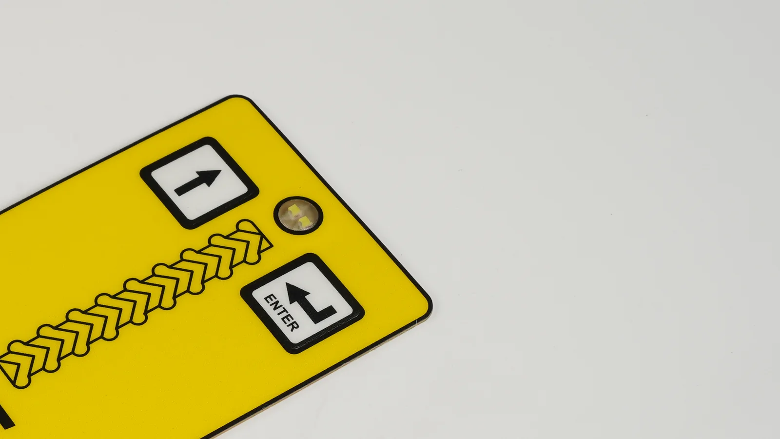
For a tactile construction, the selected dome or formed contact often establishes the mechanical floor. Its datasheet, retainer geometry, support land, spacer aperture, contact pads, and required actuation direction must fit inside the pitch. The printed target may be smaller or larger than the tactile footprint, but that relationship should be intentional and visible in a section view. Dome force, travel, and life are selected-part properties under a defined test method, not generic properties of all compact keys.
The RFQ names the tactile part or required force-displacement behavior and shows its aperture, retainer, support, and contact geometry on the same drawing.
The drawing says "smallest available dome" without a selected construction, force window, support plane, or sample method.
2.4 Coordinate emboss geometry with overlay flex
Rim, pillow, and dome embossing change finger location and local stiffness. Their tool radii, wall shape, height, spacing, and registration capability depend on the overlay film, thickness, printed layers, hardcoat, and selected forming process. Tight pitch also reduces the flat web between adjacent embossed areas. If that web flexes during one press, the neighboring tactile element may move or lose a clean snap.
The fabrication drawing names the emboss style, film, thickness, tool direction, datum, and sample acceptance method for alignment and key feel.
A full pillow emboss is added to every small key after circuit artwork is complete, with no revised stack or toolability review.
2.5 Protect circuit routing and electrical isolation
Compact keys consume routing space. Printed silver, carbon features, jumpers, LEDs, windows, shields, and a matrix return path may all compete for the channels between active areas. When a screen-printed circuit cannot meet the required route and isolation with the chosen process, a copper flexible circuit may be considered. IPC-2223E provides flexible and rigid-flex design context; it does not define the OEM's key pitch or replace the converter's documented capability.
The circuit drawing states technology, minimum trace and space, crossover method, pad geometry, insulation, pinout, and electrical acceptance limits.
Only an artwork PDF is quoted, while the circuit layer and controller pinout are deferred until after the purchase order.
2.6 Build one registration stack around shared datums
Print, cut, emboss, dome placement, circuit lamination, and enclosure mounting each contribute variation. Use one datum scheme across the graphic, circuit, spacer, and host panel. ASME Y14.5 or ISO 1101/5459 can supply the drawing language; the actual tolerance values must come from the chosen processes and feature classes. A compact keypad should be checked at worst permitted alignment, not only as a nominal overlay rendering.
Artwork, cut file, emboss drawing, circuit, and enclosure refer to the same datum features and identify the owner of every critical registration measurement.
Five files use their own origins, and approval consists of a screenshot that appears centered.
2.7 Resolve spacer aperture, venting, and sealing as one system
The spacer defines contact travel and isolates neighboring keys. Its aperture must support the selected tactile or non-tactile contact without trapping the dome edge or exposing adhesive where it can interfere with actuation. Dense cavities also need a deliberate air path. A vent path must be reconciled with any environmental barrier rather than blocked automatically in pursuit of a sealed appearance.
IEC 60529 applies IP code language to a defined enclosure test configuration. It does not grant an IP rating to a compact key grid, loose overlay, or adhesive choice. The perimeter, windows, tail exit, fasteners, vents, and enclosure joints belong to the same test article.
The layer drawing shows spacer apertures, vent route, environmental barrier, tail transition, and the exact assembly to be tested.
Individual key cavities are closed without a vent analysis, while an IP claim is copied onto the loose switch drawing.
2.8 Check tail, LED, window, and enclosure interactions
The keypad rarely occupies an empty rectangle. A display window removes routing and adhesive land. LEDs add pockets, masking, and conductors. A tail exit consumes edge space and needs a bend path, connector access, and strain relief. Enclosure ribs or screw bosses can sit beneath active keys and alter actuation. Review these features in section views and on the full assembly, not as separate component notes.
The enclosure CAD, switch DXF, circuit, LED/window map, tail route, connector, and fastener schedule are reviewed together before tooling.
The tail is drawn through the active grid or forced around an enclosure rib that is absent from the switch drawing.
2.9 Require production-intent prototype evidence
Compact membrane keypad geometry is approved by evidence. Use the final overlay stack, selected tactile element, intended mounting surface, real enclosure, controller logic, and representative operator condition. Prototyping should answer the open geometry questions before production tools and screens are locked. Record the result against drawing revision and sample identity so a later artwork or enclosure change reopens the affected checks.
The first-article plan measures alignment, actuation behavior, electrical isolation, adjacent-key response, tail clearance, and installed fit against released criteria.
The supplier and OEM approve only front-face appearance and postpone functional checks until the first production lot.
Compact geometry release table
| Decision | OEM input | Controlled drawing output | Production-intent evidence |
|---|---|---|---|
| Operator target | User, glove, posture, frequency, consequence | Target boundary and key class | Representative-user actuation trial |
| Key spacing | Hierarchy and enclosure area | Center coordinates and pitch by class | Adjacent-key response record |
| Tactile element | Feedback, force behavior, controller needs | Selected element, aperture, pads, support | Force-displacement and continuity result |
| Overlay and emboss | Film, finish, graphics, cleaning | Film stack, emboss style, tool datum | Alignment and key-feel approval |
| Circuit route | Matrix, LEDs, windows, current, connector | Trace/space, insulation, pinout, keep-outs | Electrical isolation and functional test |
| Registration | Process stack and critical features | Shared datums and tolerance allocation | Measured first-article offsets |
| Spacer and vent | Contact type, environment, seal concept | Apertures, adhesive-free areas, vent route | Stable actuation in the defined assembly |
| Enclosure interaction | Ribs, bosses, fasteners, display, tail path | Coordinated section views and 3D clearance | Installed fit and cable-access check |
| Change control | Drawing owners and revision triggers | Linked revision record | Revalidation when critical geometry moves |
Compact tactile stack diagram
Graphic overlay: legend, finish, operator target
Optional emboss tied to overlay process
Overlay adhesive and defined adhesive-free zones
Dome retainer or upper circuit
Selected tactile element
Spacer aperture plus deliberate vent route
Lower printed circuit or copper flex
Rear adhesive, backer, or mounting plate
Production-intent host enclosure
Every layer above the contact changes feel or alignment. Every routed or cut feature below it changes the available pitch. The released stack therefore needs one revision-controlled section, not a list of unrelated nominal thicknesses.
Prototype acceptance matrix
| Check | Test article and method | Acceptance record | Reopen trigger |
|---|---|---|---|
| Adjacent-key response | Representative operator, glove, posture, controller | Program-defined result by key class | Pitch, key map, overlay, or firmware change |
| Actuation behavior | Final stack on intended support with agreed instrument | Force-displacement or functional window | Dome, film, emboss, adhesive, or support change |
| Registration | Measure graphic, emboss, contact, and enclosure to shared datums | Actual offsets against released limits | Print, cut, tooling, or datum change |
| Electrical isolation | Defined neighboring-key and matrix sequence | Continuity, resistance, and decode result | Circuit, ink, insulation, or controller change |
| Tail and enclosure fit | Installed tail, connector, ribs, fasteners, and service path | Clearance and assembly-access record | Enclosure, tail, connector, or fastener change |
| Environmental configuration | Exact enclosure, perimeter, windows, vents, and tail exit | Contracted method and result | Seal path, adhesive, window, vent, or housing change |
3. Step-by-Step Process From Key Map to Approved Geometry
The following sequence keeps the operator, switch stack, circuit, and enclosure on one release path. Skipping forward usually hides a missing input rather than saving engineering time.
Step 1 - Write the use-condition statement
Record the intended operator, glove, posture, viewing angle, lighting, press frequency, cleaning exposure, and consequence of an adjacent actuation. Identify whether the control is used during motion, under time pressure, or by a trained service person. ISO 9241-210 can frame the human-centred design process, but the program owns the resulting target and test.
Step 2 - Build a key hierarchy and coordinate table
Classify controls by frequency and consequence. Put the key identifier, function, target boundary, center coordinates, intended feedback, and neighboring controls in one table. Keep safety-related or high-frequency actions visually and mechanically distinct where the risk assessment requires it. This table becomes the common input for artwork, circuit, firmware, and operator testing.
Step 3 - Select contact architecture before polishing graphics
Choose non-tactile printed contacts, discrete metal domes, formed polydomes, or another HMI technology from the required feedback, profile, environment, routing, and service conditions. For tactile keys, place the selected element, aperture, support, and contact pads beneath the key map. If those features do not fit, change the pitch, feature set, or architecture before artwork approval.
Step 4 - Run the complete geometry budget
Overlay the operator target, emboss, tactile footprint, spacer aperture, trace channels, LEDs, windows, tail route, adhesive land, fasteners, and enclosure ribs. Add process variation around shared datums using ASME Y14.5 or ISO GPS drawing language. Review worst permitted alignment. A nominal stack that fits with no tolerance allocation is not a release package.
Step 5 - Issue a compact-key RFQ package
Send the key map, artwork, circuit and pinout, selected contact behavior, layer stack, emboss drawing, enclosure CAD, tail and connector route, annual quantity for quotation, prototype quantity, and acceptance matrix. Ask the supplier to return construction assumptions, process capability for the requested features, and a red-line of geometry that requires change. Do not accept a quote that silently substitutes its own key pitch or dome.
Step 6 - Build and test the production-intent assembly
Use the intended enclosure finish and support plane, not a loose switch on a desk. Test the real glove and controller. Measure registration from shared datums, verify the required key sequence, inspect the vent and seal paths, and exercise the tail through assembly and service access. If an IEC 60529 ingress target is in scope, define the exact enclosure configuration and contracted test method before interpreting the result.
Step 7 - Lock tooling and control changes
Release emboss tools, cutting tools, screens, fixtures, and production data only after written geometry approval. Link artwork, circuit, enclosure, firmware map, sample identity, and acceptance record under one revision. Moving a key, window, rib, boss, connector, or datum should trigger a documented review of the affected checks rather than an informal visual sign-off.
4. When A Compact Membrane Keypad Is The Wrong Choice
Compact construction is the wrong choice when the available panel area cannot support the required operator target, feedback, routing, sealing, or service path. The answer may be a larger panel, fewer physical controls, a non-tactile architecture with explicit host feedback, a display-driven interface, or a silicone rubber keypad where deeper travel and glove separation outweigh membrane profile.
| Condition | Why compact membrane keys struggle | Better design response | Evidence needed |
|---|---|---|---|
| Heavy gloves or rapid repetitive entry | Neighboring targets become difficult to isolate | Increase pitch, reduce key count, or use stronger physical separation | Representative operator trial |
| High-consequence adjacent actions | One unintended press has disproportionate effect | Separate, guard, interlock, or redesign the control hierarchy | Product risk analysis and functional test |
| Dense backlighting and display openings | Optical features consume routing and adhesive land | Reallocate panel area or change HMI architecture | Day/night optical and circuit review |
| Deep travel or strong key identity | Thin film stack may not deliver the required movement | Evaluate molded silicone or mechanical controls | Comparative production-intent samples |
| Serviceable cable path cannot fit | Tail and connector interfere with active keys or enclosure | Move connector, change tail route, or enlarge interface | Assembly and service-path trial |
Stop tooling when any of these release blockers remains open:
- The key pitch is below the OEM's proven operator window and no representative trial is planned.
- The tactile element, spacer aperture, and printed target are not shown in one section.
- Artwork, circuit, emboss, and enclosure use different origins or no shared datum.
- Circuit routing is deferred until after the front graphic is approved.
- The vent route and environmental barrier contradict each other.
- A window, LED pocket, rib, boss, or fastener overlaps an active or routed area.
- The tail leaves through the key field or has no installed bend and service review.
- IP language is applied to the loose switch rather than the defined enclosure.
- Sample approval is based on appearance without operator, electrical, and dimensional evidence.
Failure chain for an underspecified pitch
Enclosure area is frozen before operator and stack inputs
->
Printed keys are reduced while tactile and circuit features remain
->
Tolerance, vent, route, or adjacent-key conflicts appear in samples
->
Artwork, tooling, enclosure, or firmware must change
->
The program pays for a second approval cycle
The useful intervention point is before RFQ: freeze the use condition and key hierarchy, then budget the complete stack against shared datums.
5. Frequently Asked Questions
How small can membrane buttons be?
There is no universal minimum membrane-button size. The smallest responsible geometry is the one that fits the defined operator target, selected contact, emboss, circuit route, spacer and vent path, and registration stack, then passes the production-intent operator and electrical acceptance plan.
How should membrane switch key spacing be selected?
Select membrane switch key spacing from key hierarchy and use conditions, not from a generic chart. Define the user, glove, posture, press frequency, neighboring controls, and consequence of an unintended actuation; then verify the proposed center-to-center pitch on the assembled interface.
Does metal dome size set the minimum pitch?
It often sets an important mechanical floor for a tactile design, but not the only one. The selected dome, retainer, spacer aperture, support land, contact pads, emboss, operator target, and process variation must all fit within the pitch shown on the controlled drawing.
Can embossing fix a layout that is too dense?
No. Embossing can improve location and local feel, but it also adds tool geometry, film strain, stiffness, and registration requirements. If adjacent embossed areas, tactile elements, or operator targets do not fit, change the pitch or architecture instead of treating emboss as a correction.
How does overlay thickness affect small keys?
Overlay material, thickness, hardcoat, printing, and emboss change local flex and perceived tactile response. Specify the complete overlay stack and approve actuation on the intended support plane; a thin graphic mockup does not prove the production key feel.
What circuit constraints matter first on a compact keypad?
Inter-key routing channels, contact pads, insulation, crossovers, LED and window keep-outs, tail exit, and connector pinout usually compete first. State the selected printed-circuit or copper-flex process and its documented trace, spacing, and registration capability before the key layout is released.
Which standards help review compact membrane-button geometry?
ISO 9241-210 supports human-centred design; ASME Y14.5 and ISO 1101/5459 provide dimension, tolerance, and datum language; IPC-2223 provides flexible-circuit design context; and IEC 60529 defines enclosure IP terminology. None supplies a universal key size, force, pitch, or finished-product result.
Should compact keypads always use metal domes?
No. Metal domes are one tactile option. Non-tactile contacts, formed polydomes, silicone keypads, capacitive interfaces, or mechanical controls may fit better depending on feedback, profile, gloves, sealing, routing, power, and service needs. Compare production-intent samples against the same use condition.
What should be sent for review before tooling?
Send the use-condition statement, key hierarchy and coordinate table, artwork, circuit and pinout, contact behavior, layer stack, emboss drawing, enclosure CAD, windows and LEDs, tail and connector route, shared datums, prototype quantity, and measurable acceptance matrix.
6. What to Do Next
Review compact button geometry before tooling. Put the operator target, key hierarchy, tactile element, emboss, circuit route, venting, tail path, enclosure features, datums, and sample evidence into one revision-controlled package. If the complete geometry does not fit, change the enclosure, key count, pitch, or HMI architecture before approving artwork.
Start with the product construction for membrane button switches and metal dome membrane switches, then use prototyping and quality testing to close the open operator, dimensional, and electrical questions. JASPER Engineering can review the compact key map and enclosure package against the evidence the first article must provide.
Review the key map before tooling is released
Send the use condition, key map, artwork, circuit and pinout, selected contact behavior, layer stack, emboss drawing, enclosure CAD, tail route, shared datums, and acceptance priorities. JASPER Engineering will identify the geometry decisions that still need evidence.