
Task and hierarchy
Release controlMap frequent actions, navigation, numeric entry, alarms, confirmation, cancel, and service functions.
If it is missingEvery key looks equal and operators hesitate or select the wrong action.
A good button panel is designed around the task, not a neat grid. Key size, pitch, reach, glove use, visual hierarchy, tactile feedback, matrix routing, debounce behavior, and error recovery determine whether operators can use the interface accurately.
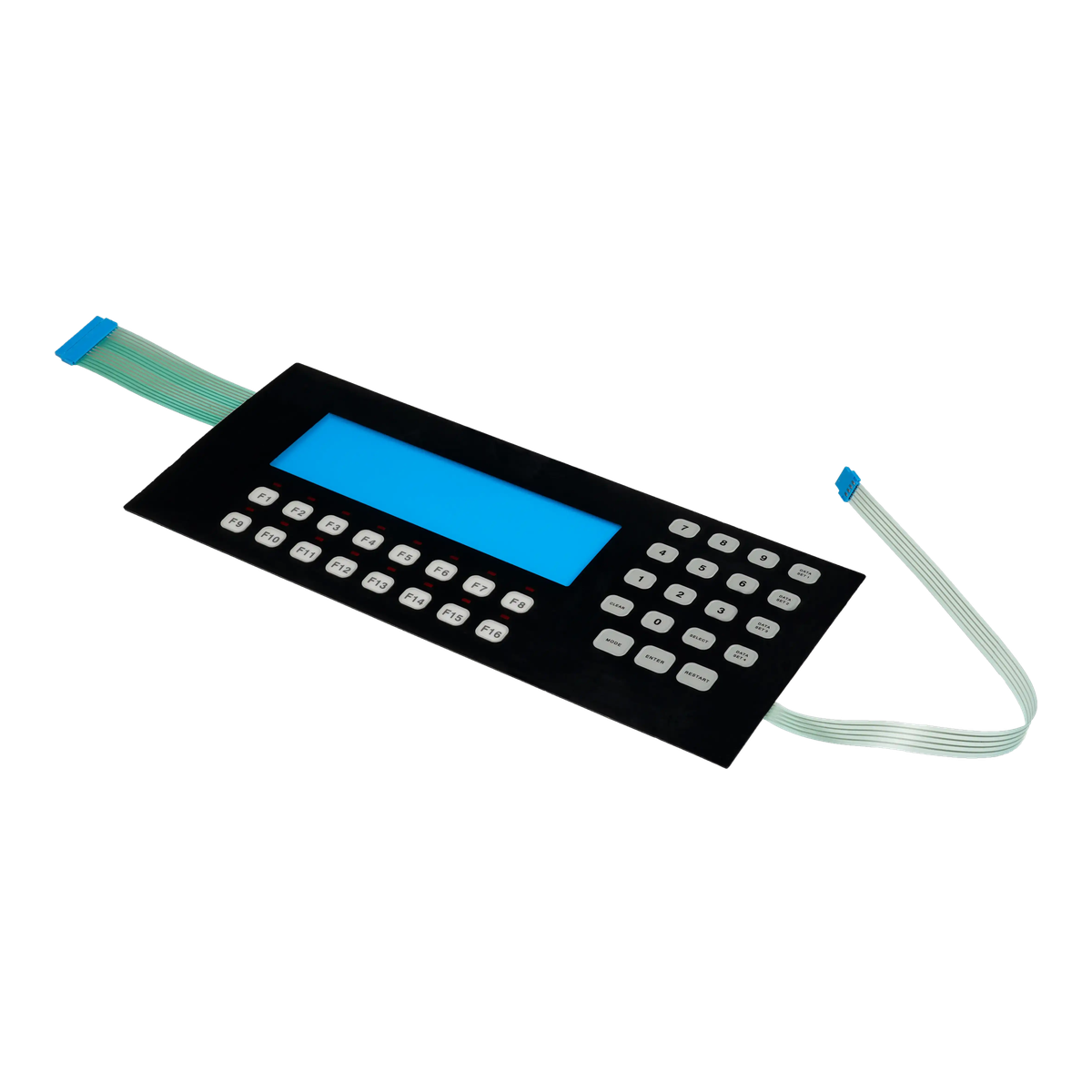
Membrane button switches can be tactile or non-tactile, flat or embossed, compact or widely spaced. The right arrangement depends on how often each key is used, whether the operator looks at the panel, and whether gloves, vibration, low light, or public use change the task.
Artwork cannot rescue poor key geometry. Active area, spacing, emboss boundary, actuator support, finger approach, and enclosure edge all influence whether a user can press one key without hitting the next.
The circuit matrix must be released with the visible layout. Late pinout or routing changes can move tail exits, enlarge the spacer, create ghosting risk, or force artwork changes after the mechanical panel is approved.
The visual layout, physical load path, and circuit matrix should be reviewed in the same drawing package.
Map frequent actions, navigation, numeric entry, alarms, confirmation, cancel, and service functions.
If it is missingEvery key looks equal and operators hesitate or select the wrong action.
Review active area, center spacing, finger size, glove use, reach, enclosure edge, and adjacent-key risk.
If it is missingKeys fit the drawing but are difficult to press accurately.
Choose metal dome, flat contact, emboss, actuator, click sound, system feedback, and required force.
If it is missingThe user cannot tell whether a command registered or the key feels inconsistent.
Control legend position, ink stack, hard coat, emboss strain, window clearance, and cleaning exposure.
If it is missingHigh-use legends crack, polish, fade, or become hard to read.
Release rows, columns, common lines, diode or controller assumptions, ghosting limits, tail, and connector.
If it is missingThe visible key map no longer matches the electrical interface.
Define key scan, simultaneous presses, force, visual inspection, tail handling, connector, and installed usability checks.
If it is missingA continuity pass is mistaken for operator-interface approval.
Use the table to align ergonomics, artwork, mechanics, and electronics.
| Decision | Options to review | Release question |
|---|---|---|
| Key layout | Numeric, navigation, function, confirmation, emergency, service, single or grouped keys | Which actions deserve the largest and clearest positions? |
| Physical response | Tactile dome, non-tactile, pillow or rim emboss, flat overlay, actuator, audible or system feedback | How will the user confirm a successful press? |
| Graphics | Legends, icons, colors, dead-front areas, hard coat, texture, backlighting, display relationship | Will critical labels remain clear through the expected wear and lighting? |
| Circuit | Matrix, individual circuits, common lines, pinout, tail exit, connector, shielding, LEDs | Does the electrical map match the approved visible layout? |
| Approval | Force, edge press, glove use, key scan, simultaneous input, cleaning, abrasion, installed usability | Which sample checks prove the keypad works in the real task? |
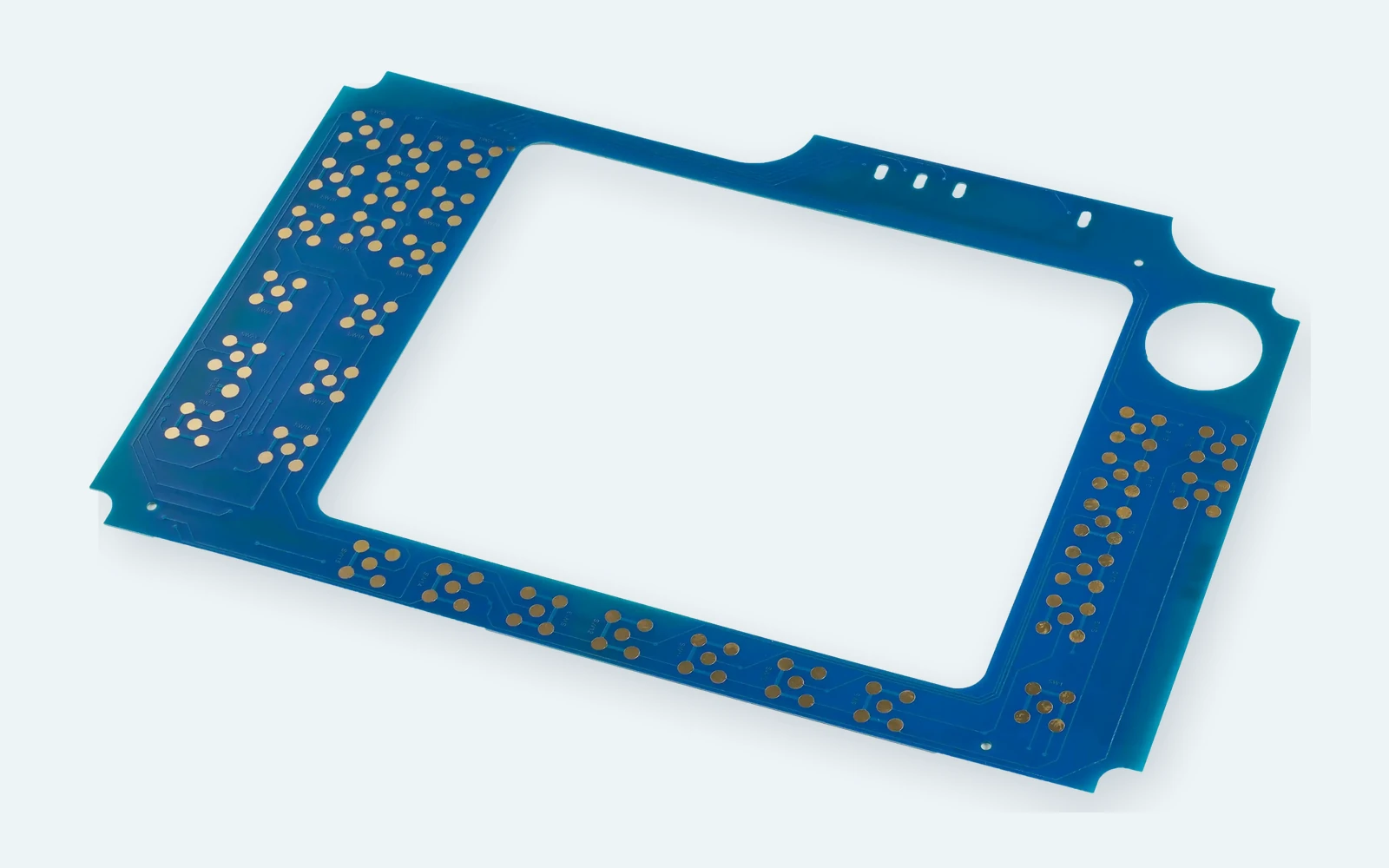
A button can move visually without appearing to change the circuit, but the new route may affect row-column assignments, tail width, connector pinout, spacer vents, LED placement, and simultaneous key behavior.
Prioritize frequent, critical, numeric, navigation, confirmation, cancel, and service actions.
Define active areas, pitch, emboss, actuator, glove use, edge press, enclosure limits, and display relationship.
Tie key identifiers, legends, LEDs, matrix, pinout, tail, connector, and controller assumptions together.
Check visual hierarchy, press accuracy, tactile response, key scan, simultaneous input, cleaning, and wear.
Lock artwork, materials, domes, circuit, fixture, key map, pinout, labels, inspection, and packaging.
Review active area, center pitch, emboss boundary, finger or glove size, enclosure edge, and visual grouping.
Check ink stack, emboss strain, hard coat, texture, cleaning chemicals, press location, and abrasion exposure.
Compare artwork revision, circuit map, connector numbering, firmware labels, fixture, and inspection drawing.
Review actuator support, venting, spacer relief, dome or contact position, edge loading, enclosure flatness, and adhesive pressure.
Numeric entry, confirm, cancel, and status functions in a compact sealed front.
Cleanable keys with clear hierarchy, repeatable feedback, and controlled artwork.
Navigation and function buttons designed for gloves, noise, vibration, and repeated use.
Space-efficient command layouts with low profile, light weight, and flexible tails.
Cost-controlled button groups integrated with icons, displays, LEDs, and enclosure adhesive.
Frequent numeric and menu inputs with clear labels, tactile confirmation, and stable pinout.
The best button layout review starts with what users do, what they must not do by mistake, and how the controller interprets each press.
Size depends on finger or glove, press angle, frequency, enclosure edge, adjacent-key risk, and whether the user looks at the panel. Review active area and center pitch with a full-size sample rather than relying on a universal number.
Use tactile feedback when operators need physical confirmation. Non-tactile keys can be appropriate when the system provides immediate visual, audible, or display feedback and low profile or quiet operation matters.
Yes. Pillow, rim, dome, or selective embossing can identify and guide the press area. The emboss must be coordinated with the key contact, actuator, overlay material, legend, spacer, and expected flex life.
Increase pitch or separation, clarify graphic grouping, adjust key size, use emboss boundaries, review glove dimensions, protect enclosure edges, and test realistic press angles.
Yes. Status LEDs, dead-front indicators, or illuminated legends can be included when component height, power, optical masking, light leakage, matrix routing, tail, and sample acceptance are defined.
Send the visible key map, circuit matrix or controller interface, pinout, simultaneous-key rules, tail and connector, tactile preference, artwork, enclosure, quantity, and test requirements.
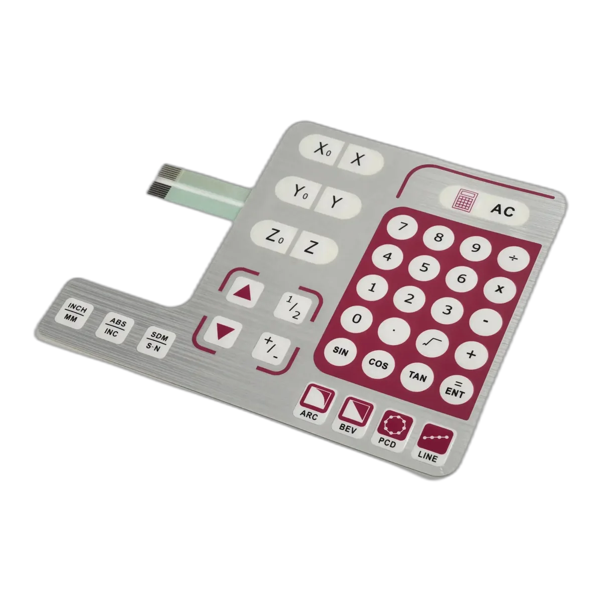
Review the broader keypad route for dense numeric and multi-function layouts.
Review Route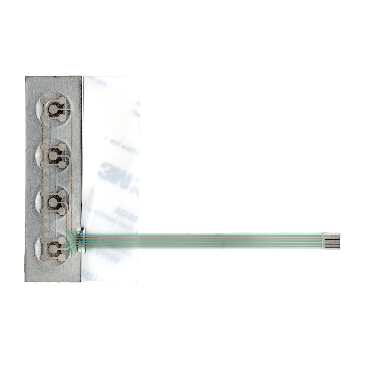
Focus on force curve, dome array, pad, actuator, and lifecycle when tactile snap is critical.
Review Route
Prepare matrix, pinout, simultaneous key, tail, connector, and electrical test inputs.
Review RouteJASPER can review key hierarchy, pitch, tactile response, artwork, matrix, tail, connector, enclosure, and sample test plan before tooling.
Share the project basics. JASPER will review the stack, materials, connector, quantity, and production risks.