
Passenger seat occupancy sensor false positives cannot be solved by choosing a kilogram threshold in isolation. OEM seat, electronics, and validation teams must define which occupants and objects count, freeze the installed seat stack, then test the sensor output and decision logic across posture, foam preload, temperature, vibration, and time. This guide builds that boundary without claiming vehicle-level safety or compliance.
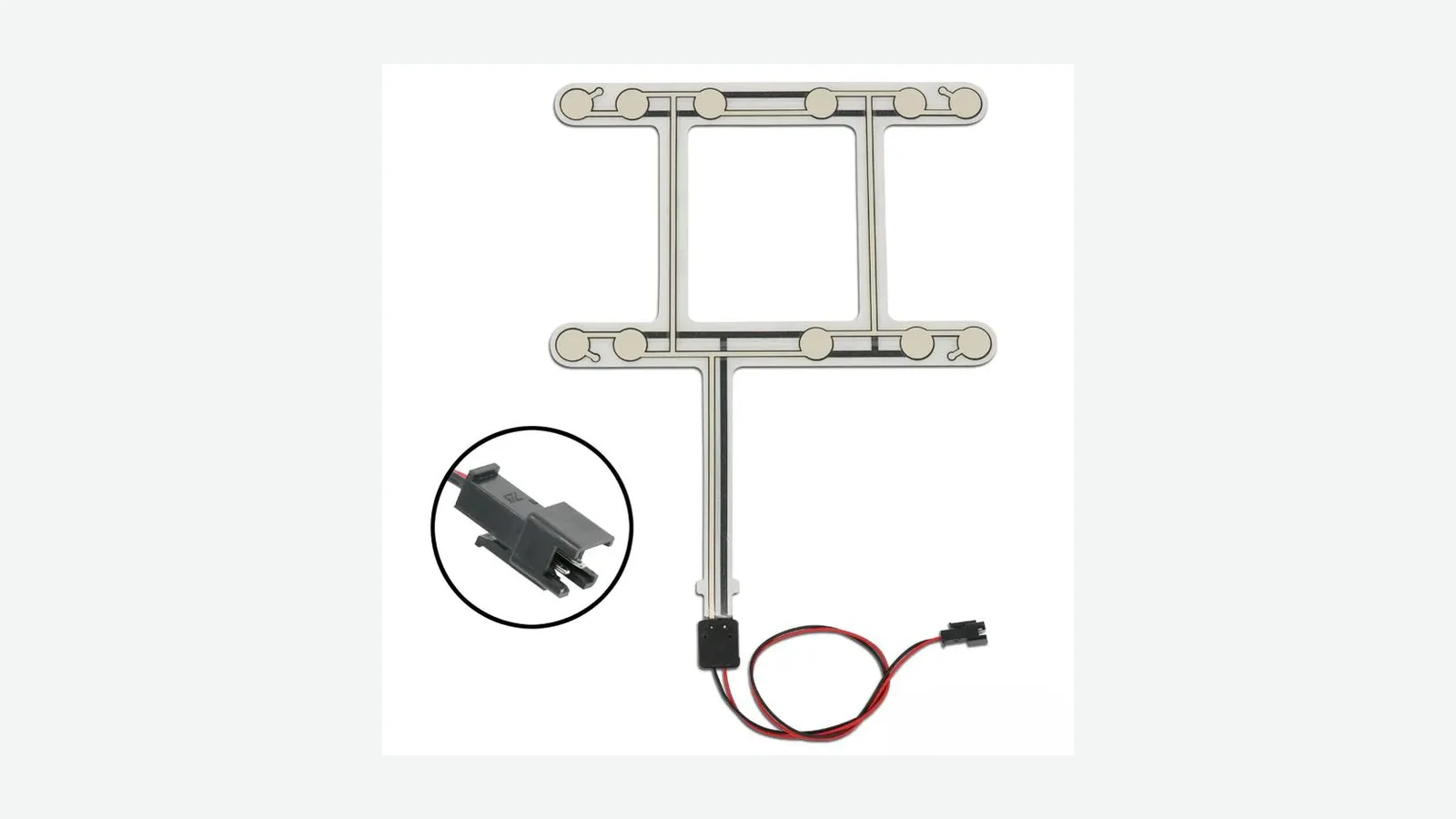
A passenger seat sensor does not observe “a person.” It observes pressure, force, capacitance, or another physical variable after the seat has transformed the load. The decision may then pass through threshold, hysteresis, debounce, diagnostics, and vehicle logic. This article addresses pressure- and membrane-based component projects. It does not validate an occupant classification system (OCS), control an airbag, or establish compliance with FMVSS No. 208.
Passenger seat occupancy sensor false positives are boundary failures across the installed seat, sensor response, electronics, threshold logic, and state timing. The review must trace each layer before a sensor geometry or threshold is changed.
1. Define the Error Before Changing the Sensor
A false result needs a reference truth and a required output. Without both, “false positive” is ambiguous. For a binary presence input, a false occupied result means the seat is actually in a case defined as empty but the system reports occupied. A false unoccupied result is the reverse. An indeterminate state, a diagnosed electrical fault, and a wrong adult/child classification are different outcomes with different corrective actions.
This distinction matters in current regulatory language. The April 6, 2026 NHTSA interim final rule for seat-belt reminders allows a baseline rear-seat warning path that does not depend on occupant detection. It also describes separate provisions for voluntarily fitted occupant detection. The rule therefore demonstrates a broader engineering point: buckle state, occupied state, warning state, and occupant class are not interchangeable signals (Federal Register, 91 FR 17145).
| Actual case under the project specification | Required sensor/system state | Wrong result | Engineering label |
|---|---|---|---|
| Empty production seat, no allowed object | Empty | Occupied | False occupied / nuisance detection |
| Required occupant in an approved posture | Occupied | Empty | False unoccupied / missed detection |
| Object or posture declared outside scope | Excluded or indeterminate | Any forced binary result | Requirements gap, unless a fallback is specified |
| Open circuit, short circuit, disconnected tail | Fault | Empty or occupied with no fault indication | Diagnostic coverage failure |
| Child restraint or occupant class requiring a distinct vehicle response | Project-specific class | Wrong class | Misclassification, not merely a presence false positive |
The project team should write one sentence for every row in its real use case: “Given case X, in seat build Y, after conditioning Z, the required output is state Q within time T.” That sentence turns seat sensor false detection from a complaint into a testable requirement.
A pressure-based passenger seat occupancy sensor can support a presence input when its sensing principle matches the required boundary. It cannot identify the object that produced an overlapping pressure pattern unless geometry, multiple zones, temporal logic, or another sensing modality creates separable evidence.
2. How Passenger Seat Occupancy Sensor False Positives Form
The useful diagnostic unit is a five-layer chain, not the sensor film alone:
Real case
Seat load path
Sensor response
Signal decision
Vehicle function
A laptop bag may be a legitimate false-occupied challenge at the first layer. Foam and trim spread its load at the second. A sensing zone converts that distribution into a contact, resistance, voltage, or count at the third. Threshold and timing logic assign a state at the fourth. Only then does the vehicle decide what to display or do. An automotive HMI and sensing application must assign each of these layers to an owner. Calling the final symptom “a bad sensor” skips four possible causes.
2.1 Bags and concentrated objects
Cargo can create a pressure distribution that overlaps a human boundary. A compact bag may load one central zone strongly; a broad parcel may spread a lower pressure across several zones. An object wedged between the cushion and console can also preload the seat. Ford’s 2022 Expedition owner guidance lists objects under the seat, between the cushion and console, on an occupant’s lap, in the map pocket, or hanging from the backrest as conditions that can make a properly seated person appear heavier or lighter to that vehicle’s front passenger sensing system (Ford Service Content).
A binary pressure mat cannot always reject cargo while detecting every required occupant. If the signal distributions overlap after installation variation and temperature conditioning, the team must narrow the accepted cases, change zone geometry, add features to the signal model, or choose another sensing method. Moving the threshold merely trades one error type for another.
2.2 Child restraints and project scope
A child restraint is not just “a heavy object.” Its feet, base, support leg, belt tension, orientation, and contact patch create a distinct load path. The required response also depends on system purpose. A simple seat-belt reminder input, a presence detector, and a front-passenger OCS can require different states for the same installed restraint.
NHTSA’s 2026 rear-seat reminder rule illustrates why copied weight values are dangerous. For one occupied-seat test option, it specifies either a 49 CFR part 572, subpart N six-year-old dummy or a human at least 21 kg (46.5 lb) and 114 cm (45 in). Those values belong to that rear-SBR provision; they are not a universal front-passenger occupant sensor threshold and do not define a membrane switch point.
2.3 Posture and off-center loading
A person can move the effective load away from the intended zones by slouching, leaning, sitting on a bolster, rotating, lifting through an armrest, or bracing with their feet. Ford’s owner guidance asks an adult-size passenger to sit upright and centered, and it lists rear-passenger feet or knees pushing on the seat as possible interference. That is model-specific guidance, but it supports a general test-design rule: required postures and excluded postures must be named rather than left to the technician.
An OEM team should record the pressure or electrical trace during posture transitions, not only after the occupant settles. Ingress, egress, reaching, braking, and road input may cross a threshold briefly. Whether that transition counts depends on persistence time and vehicle logic.
2.4 Foam preload, trim, and installed hardware
The sensor sees the assembled seat. Foam density, molded channels, local stiffness, cover tension, listing wires, clips, heaters, ventilation layers, seams, hook-and-loop strips, and adhesive placement can alter the unloaded baseline or transfer load away from the active area. A drawing that shows only the sensor outline is therefore incomplete.
Vehicle OCS architectures include track sensors, gel-filled bladders, and seat mats. Debris, seat changes, and objects attached to the backrest can affect readings. The source is repair-oriented, not a design standard, but it confirms that OCS architectures and load paths vary by vehicle (FenderBender).
2.5 Temperature, vibration, and time
Temperature can change foam modulus, trim tension, adhesive behavior, conductor resistance, and electronics. Vibration and seat motion can modulate contact force. ISO 16750-3:2023 identifies mechanical loads for road-vehicle electrical/electronic components; ISO 16750-4 addresses climatic loads. Neither standard supplies a universal seat-sensor severity. The OEM must select conditions for the component’s mounting location and system requirement (ISO 16750-3:2023; ISO 16750-4).
Testing temperature and vibration only with an obviously empty seat and an obviously occupied seat misses the boundary. Cross each condition with the lightest required occupant, the heaviest excluded object, the highest allowed preload, and the postures nearest the decision edge.
3. The Nine-Point Detection-Boundary Framework
The framework below is for design reviews, RFQs, and sample approval. It does not replace an OEM design-validation plan, functional-safety process, or legal compliance assessment.
3.1 Define the output and the error taxonomy
Start with the electrical interface and states. A switch-like mat may expose open/closed contact; a resistive or analog construction may expose a range; an intelligent module may report occupied, empty, indeterminate, and fault. Document units, polarity, valid range, update rate, and behavior during startup and disconnection.
the requirement distinguishes false occupied, false unoccupied, indeterminate, and electrical fault, with a denominator and observation window for each metric.
a request says “zero false positives” but never defines truth state, excluded cases, sample population, repetitions, or whether a diagnostic fault counts.
3.2 Declare expected and excluded detection cases
Build a case inventory before drawing the sensing pattern. Include an empty seat, required occupants, bags, rigid parcels, child restraints, seat accessories, wet garments if relevant, occupied postures, ingress/egress, neighboring-passenger interference, and service states. Give each case a required output or mark it excluded with a specified fallback.
An exclusion is not a loophole. It is a design boundary that must be visible to the vehicle-system owner. If the vehicle must distinguish a rear-facing child restraint from luggage, “both are excluded” is not an acceptable system requirement.
every challenge object has dimensions, mass, placement, orientation, conditioning, and required output.
the test lab chooses “a typical backpack” on the day of testing.
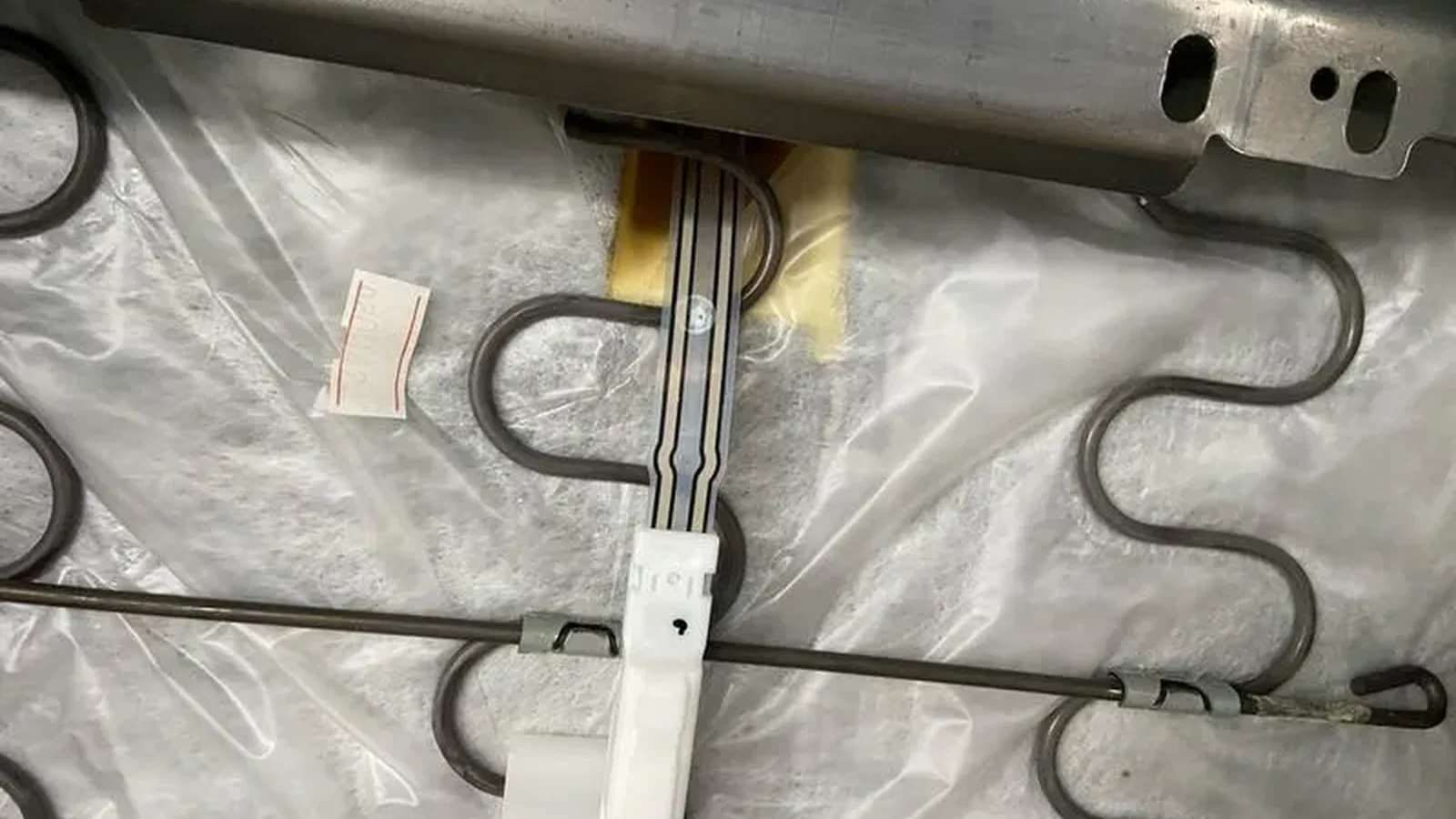
3.3 Freeze the installed seat stack
The controlled item is the assembled seat, not a free sensor on a bench. Assign identifiers to the foam tool and revision, trim material and sewing pattern, cover tension method, heater or ventilation layer, attachment hardware, sensor location, adhesive, tail exit, connector, frame, and seat adjustment position. Capture photographs and section drawings.
Changes that appear cosmetic can move the baseline. A thicker trim laminate or a relocated listing wire may preload an active zone. A tail routed over a foam edge may also add local force or create a durability problem unrelated to the active area.
the boundary test report names every seat-stack revision and records assembly variation across more than one seat build.
a prototype passes in hand-cut foam, then the production foam/trim stack changes without regression testing.
3.4 Map the load path to the sensing zones
Use pressure mapping, load-transfer film, instrumented fixtures, or repeated raw-signal measurements to learn where accepted occupants load the cushion. Compare centered, forward, rearward, lateral, and bolster-biased postures. Then compare excluded objects using the same seat and conditions. Ford’s 2022 Expedition guide provides a concrete OEM example: objects under the seat, between the cushion and console, or hanging from the backrest can alter that vehicle’s interpretation (Ford Service Content).
The purpose is not to maximize active area. More area can increase object sensitivity and foam-preload exposure. The pattern should capture the features that separate required cases from excluded cases while tolerating manufacturing variation.
each proposed zone has a reason tied to a required posture or discrimination problem, and the team stores raw traces rather than only a binary lamp state.
the active area is copied from a different seat width or foam architecture.
3.5 Specify the occupant sensor threshold, hysteresis, and timing
An occupant sensor threshold is the decision boundary applied to a defined signal under defined conditions. It is not automatically equal to occupant mass. The seat converts body mass and posture into distributed force; the sensor and conditioning circuit convert that force into an electrical signal. NHTSA’s April 2026 rulemaking shows why scope must travel with every number: its 21 kg / 114 cm condition is tied to a specific rear-SBR test option, not a generic sensor setting (Federal Register, 91 FR 17145).
At minimum, specify:
| Parameter | Question the requirement must answer |
|---|---|
| Unloaded baseline | What range is valid for each seat build and condition? |
| Occupied threshold | Which signal transition requests occupied state? |
| Release threshold | Which signal transition returns to empty state? |
| Hysteresis | What separation prevents chatter near the boundary? |
| Debounce / persistence | How long must the condition persist before state changes? |
| Sampling / filtering | Which transient content is retained or rejected? |
| Initialization | Is zeroing allowed, when, and with what seat state? |
| Ownership | Which functions reside in the sensor, seat controller, or vehicle ECU? |
If the occupied and release thresholds are identical, small noise or posture motion can produce rapid toggling. Hysteresis reduces chatter but creates a history-dependent region. Debounce rejects short excursions but adds latency. These are system tradeoffs, so the owner of each function must be explicit.
the RFQ includes raw signal bands and asks the supplier to preserve margin; the vehicle team retains final state-machine ownership unless an intelligent module is in scope.
a single “trigger weight” is copied from a regulation, competitor, or unrelated seat.
3.6 Cross operating conditions with boundary cases
A condition test and a detection test should not live in separate plans. If cold foam transfers load differently, the lightest required occupant must be tested cold. If vibration can create contact chatter, the empty/preloaded seat and an edge-case occupant must be observed during representative mechanical input. ISO 16750-3:2023 names mechanical loads for road-vehicle electrical/electronic components, while ISO 16750-4 covers climatic loads (ISO 16750-3:2023; ISO 16750-4).
Use ISO 16750-3 and ISO 16750-4 as test-family references when the OEM specification invokes them, then tailor severity to mounting location. Include supply voltage and grounding variation when active electronics are present. For a passive mat, include the customer’s pull-up, excitation, measurement current, and filtering because the same element can appear different behind another circuit.
the matrix crosses temperature, mechanical input, seat position, and assembly variation with the cases closest to each decision boundary.
environmental tests check continuity afterward but never record detection state during or immediately after conditioning.
3.7 Separate component, seat-system, and vehicle acceptance
NHTSA reported that about 7% of MY2022 U.S. vehicles had rear-seat occupant detection, while its baseline rear warning path could operate from buckle-state information without occupant detection (Federal Register, 91 FR 17145). That statistic does not describe front-seat OCS fitment; it shows why the project must state whether occupancy sensing is mandatory, optional, or outside the warning architecture.
Three levels prevent scope inflation. This separation follows the boundary visible in 49 CFR §571.208: NHTSA regulates vehicle occupant-crash-protection performance, whereas a sensor drawing defines only one input component (eCFR).
| Level | Typical input | Measured output | Evidence owner |
|---|---|---|---|
| Sensor component | Applied fixture load or controlled contact | Resistance, contact state, voltage, raw counts, insulation, open/short response | Sensor supplier + customer |
| Assembled seat | Defined occupant/object/posture in a controlled seat build | Raw channel data and requested occupied/empty/fault state | Seat/OEM engineering |
| Vehicle system | Seat state, buckle state, diagnostics, other sensors, software | Warning, telltale, classification, or other vehicle behavior | Vehicle manufacturer / system integrator |
FMVSS No. 208 is titled “Occupant crash protection” in 49 CFR §571.208 (eCFR, current §571.208). A component supplier’s continuity test cannot demonstrate compliance with that vehicle standard. Nor can a passed seat-mat test prove airbag suppression or deployment behavior.
each requirement has one verification level and one accountable owner.
the purchase drawing says “FMVSS 208 compliant sensor” with no vehicle test, system definition, or allocation.
3.8 Include drift, assembly, and diagnostic behavior
Measure unloaded baseline before and after seat assembly, conditioning, repeated occupancy, connector cycling, and defined service operations. Decide whether calibration is fixed, learned, or prohibited. For learned systems, define when an empty reference may be accepted and how a loaded seat at startup is handled.
Electrical diagnostics need separate fault insertion. Open circuit, short to ground, short to supply, cross-channel short, intermittent connector, and out-of-range analog response should not masquerade as a valid empty or occupied state. ISO 16750-3:2023 can organize mechanical-load exposure around the mounting location, but the OEM—not the sensor supplier’s website—must set the severity (ISO).
baseline, span, drift, and diagnostic responses are trended by sensor serial number and seat build.
a moved baseline is “fixed” by changing the threshold after every prototype round without closing the mechanical cause.
3.9 Require traceable samples and evidence
A credible passenger presence sensor validation record must allow another engineer to reconstruct the result. Store seat build ID, foam and trim lots, sensor serial/revision, connector and harness revision, controller hardware/software, calibration file, environmental state, object/occupant definition, placement, raw signal, derived state, timestamps, photos, and disposition.
The starter matrix below uses three repeats per cell as a initial planning minimum, selected as a practical mid-to-upper pilot value rather than a statistical validation claim. Replace it with the OEM’s sample-size, confidence, reliability, and regulatory plan before design validation.
raw traces and configuration records remain linked to every pass/fail decision.
only a photograph of the instrument panel telltale remains after testing.
4. When a Pressure or Membrane Seat Mat Is Not the Best Choice
A thin pressure or membrane mat is attractive when the required output is presence in a known seat, the load path is controlled, and accepted and excluded cases remain separable after variation. It is not automatically the right architecture for object identity, posture classification, or occupant classification.
| Requirement | Pressure/membrane mat fit | Consider instead or add |
|---|---|---|
| Binary presence with controlled seat stack | Often suitable after seat-level validation | Multi-zone mat if posture coverage is weak |
| Distinguish human from a similarly loaded bag | May be insufficient when signal distributions overlap | Capacitive sensing, sensor fusion, or revised system requirement |
| Distinguish adult, child, and child restraint | A simple binary mat is not enough | Validated OCS architecture with multiple features/modalities |
| Detect occupant without relying on cushion load | Poor fit | In-cabin radar, camera, or another non-load modality, subject to system requirements |
| Map pressure distribution for comfort or posture | Switch-like output is too limited | Pressure array or multi-channel force sensing |
| Seat-belt reminder that can use buckle-only logic | Occupancy input may be optional depending on jurisdiction/system | Buckle sensing and compliant warning logic |
IEE BodySense uses an ECU-linked capacitive front-passenger classification architecture intended to distinguish adult occupants and child restraints (IEE BodySense). Capacitive sensing is not universally better, but another physical variable may be necessary when pressure-only boundaries overlap.
The car seat occupancy sensor family should therefore be selected from the use-case boundary backward, not from a preferred construction forward.
5. Passenger Presence Sensor Validation: A Six-Step Workflow
Step 1 — Allocate the function
Write what the sensor supplies and what remains in the seat controller or vehicle ECU. Define empty, occupied, indeterminate, and fault states; startup behavior; update time; diagnostics; and the downstream function that consumes the state. Keep airbag/OCS and seat-belt-reminder requirements in separate allocation rows.
Step 2 — Build the accepted/excluded case library
Create controlled fixtures or descriptions for bags, rigid cargo, child restraints, occupant statures, clothing, postures, and interference. Record geometry, mass, contact features, orientation, placement tolerance, and required result. Regulatory fixtures must be taken from the applicable requirement, not approximated by a supplier. The April 2026 NHTSA rule, for example, names 49 CFR part 572, subpart N and a separate 21 kg / 114 cm human option for one rear-SBR test path (Federal Register).
Step 3 — Instrument the real seat
Use production-intent foam, trim, attachments, heater/ventilation layers, frame, and harness. Record raw sensor output alongside seat position and environmental state. If possible, inspect the physical load path with pressure mapping or a repeatable force-distribution fixture before freezing zone geometry.
Step 4 — Characterize distributions before setting logic
Plot empty and occupied results for each case, seat build, condition, and repeat. Look for overlap, not just mean separation. Choose an occupied threshold, release threshold, hysteresis, and timing only after seeing the worst-case tails. If accepted and excluded distributions overlap, do not hide it with a nominal threshold.
Step 5 — Run the crossed boundary matrix
Test nearest-neighbor cases at temperature and during representative mechanical input, then repeat after defined conditioning and assembly variation. ISO 16750-3:2023 and ISO 16750-4 can organize mechanical and climatic families when invoked by the OEM (ISO 16750-3:2023; ISO 16750-4). JASPER’s component and assembly testing page is the planned capability link; the actual severities and acceptance criteria still come from the customer’s validation plan.
Step 6 — Freeze evidence and change control
Approve the sensor drawing together with the seat stack, controller logic, test matrix, and evidence set. Define which changes trigger regression: foam tool, trim laminate, stitching, heater, sensor material, adhesive, pattern, tail, connector, controller hardware, software, calibration, or assembly method. A passed sample is not transferable to an uncontrolled seat revision.
6. Starter Boundary Test Matrix
This matrix is a planning scaffold, not a compliance procedure. Replace case definitions, environmental severities, repetitions, and pass criteria with the OEM program requirements. Run at least the cells nearest both sides of the decision boundary across multiple production-intent seat builds.
| Case family | Concrete setup | Condition cross | Required state | Record |
|---|---|---|---|---|
| Empty baseline | Fully assembled seat; no object; each allowed seat position | Nominal, conditioned low/high temperature, after vibration/conditioning | Empty; no chatter | Raw baseline, drift, state transitions |
| Allowed empty-seat accessories | Approved cover/accessory if any | Installation tolerance and temperature | Project-defined empty | Accessory ID, placement, preload |
| Bag / cargo | Lightest-to-heaviest excluded objects; center, front edge, lateral edge, bolster | Temperature, braking/road input where specified | Empty or excluded-state behavior | Geometry, mass, contact patch, trace |
| Rigid object | Box/tool case with concentrated supports | Orientation and placement tolerance | Empty or excluded-state behavior | Support locations and peak channels |
| Child restraint | Each required orientation/model/fixture from system plan | Belt/anchor tension, support leg, seat position | Project-specific; never assumed | Restraint ID, installation, tension method |
| Lightest required occupant | Defined anthropometry/fixture and clothing | Centered plus allowed posture tolerance; environmental boundaries | Occupied within specified time | Raw distribution, margin, timing |
| Nominal occupant | Upright centered posture | Nominal and environmental regression | Occupied | Baseline reference and repeatability |
| Off-center posture | Forward, rearward, left/right, bolster-biased | Static and specified dynamic input | Occupied if posture is accepted | Position fixture, trace, transitions |
| Temporary unload | Reaching, bracing, lifting through armrest | Duration sweep | Remain occupied or follow specified timing | Dropout duration and hysteresis behavior |
| Ingress / egress | Controlled entry and exit sequence | Seat/vehicle state and timing | No unintended latched state | Transition timestamps |
| Neighbor interference | Rear knees/feet, console contact, object under track if within misuse plan | Seat adjustment extremes | Defined excluded/fault/normal response | Interference location and force method |
| Electrical fault | Open, short, intermittent connector, out-of-range channel | Startup and running | Fault, not valid occupancy | Diagnostic code/state and latency |
| Post-conditioning | Repeat nearest empty and occupied boundary cases | After mechanical/climatic/assembly conditioning | Same acceptance limits or approved drift | Before/after trace and seat build ID |
Exploratory repetition rule: Run three repeats per cell to expose gross instability during early characterization. The released design-validation sample size must follow program risk, measured variation, confidence targets, regulatory scope, and OEM policy.
A seat occupancy sensor mat drawing should reference the approved matrix revision so the active-zone design and the accepted cases do not drift apart.
7. RFQ and Sample Approval Checklist
Send the following before requesting a sensor threshold or quotation-ready design review:
- [ ] Seat assembly drawing, cushion section, foam tool/revision, and trim stack
- [ ] Sensor installation plane, available envelope, keep-outs, and attachment method
- [ ] Accepted occupant cases with posture and placement tolerance
- [ ] Excluded objects and child-restraint cases with required outputs
- [ ] Empty, occupied, indeterminate, and fault-state definitions
- [ ] Raw electrical interface: units, circuit, excitation, pull-up, sampling, and valid ranges
- [ ] Occupied threshold, release threshold, hysteresis, debounce, and function owner
- [ ] Active-zone rationale and any multi-zone channel allocation
- [ ] Tail route, bend controls, strain relief, connector, and harness interface
- [ ] Seat adjustments, heater/ventilation layers, bolsters, listing wires, and nearby hardware
- [ ] Mechanical, climatic, electrical, and post-conditioning test plan
- [ ] Seat-build/sample count, exploratory repeats, and final statistical plan
- [ ] Raw-data format, software/calibration ID, photo record, and traceability fields
- [ ] Change-control list and regression-test triggers
- [ ] Clear statement of component-, seat-, and vehicle-level evidence ownership
A supplier can then review geometry and sensing construction against a real boundary. Without these inputs, a quoted “trigger weight” is only a nominal guess.
8. Frequently Asked Questions
What causes passenger seat occupancy sensor false positives?
False occupied results occur when an empty-seat case produces a signal inside the occupied decision region. Common paths include cargo pressure, foam or trim preload, seat attachments, nearby objects, baseline drift, threshold overlap, and transient logic. The cause may sit in the seat stack, sensor, electronics, or state machine.
Is occupant weight the same as the occupant sensor threshold?
No. Occupant mass is transformed by posture, cushion geometry, foam, trim, and sensing area before it becomes an electrical value. The occupant sensor threshold must therefore be specified in the measured signal domain and tied to an installed seat, conditions, hysteresis, and timing.
Can one threshold distinguish a passenger from a bag?
Only if the required passenger cases and excluded bags produce separable sensor-output distributions under all specified variation. If those distributions overlap, threshold tuning alone cannot solve the problem. Zone geometry, additional features, a second sensing modality, or a narrower requirement is needed.
How should child seats be handled in passenger presence sensor validation?
List every required child-restraint case with model or regulatory fixture, orientation, installation method, belt or anchor tension, support-leg condition, seat position, and required output. Do not treat NHTSA’s rear-SBR 21 kg / 114 cm option as a universal front-seat threshold; its scope is specific.
Why test posture if the sensor only needs presence?
Posture changes where load enters the cushion. Leaning, slouching, bolster loading, bracing, and temporary unloading can reduce or move force away from active zones. The validation plan must state which postures remain accepted and how long a signal excursion may persist before the state changes.
Which standards are relevant to seat sensor false detection testing?
49 CFR §571.208 is relevant to U.S. vehicle-level occupant crash-protection and warning requirements. ISO 16750-3:2023 and ISO 16750-4 identify mechanical and climatic test families for road-vehicle electrical/electronic components. None supplies a universal membrane-sensor threshold or proves JASPER compliance.
How many repetitions are needed in a boundary test matrix?
Three repeats per cell expose gross instability during exploratory characterization but do not establish reliability or field error rate. Set the final sample size and repetitions from program risk, measured variation, confidence targets, regulatory requirements, and OEM policy.
What should a sensor supplier receive before prototype design?
The supplier should receive the production-intent seat stack, installation envelope, accepted/excluded case library, raw electrical interface, threshold and timing ownership, active-zone requirements, tail/connector constraints, environmental plan, sample strategy, evidence format, and change-control rules. A physical seat sample is valuable when drawings cannot show the load path.
9. Define the Boundary Before Freezing the Sensor
The next useful deliverable is not a target weight. It is a signed table of expected and excluded detection cases, connected to the seat stack, raw signal, threshold logic, test conditions, and evidence owner. That table reveals whether a pressure or membrane construction has enough separation—or whether the system needs more zones or another modality.
Technical References
- Source: 49 CFR 571.208 Occupant Crash Protection. Accessed 2026.
- Source: NHTSA Occupant Classification System Investigation DP16-001. Accessed 2026.
- Source: NHTSA Recall 19V-343 Occupant Classification Sensor Placement. Accessed 2026.
- Source: SAE 2005-01-0461 Occupant Classification Sensor Mat Layout. Accessed 2026.
- Source: ISO 26262 Road Vehicle Functional Safety. Accessed 2026.
- Source: Federal Register, 91 FR 17145. Accessed 2026.
- Source: Ford Service Content. Accessed 2026.
- Source: FenderBender. Accessed 2026.
- Source: ISO 16750-3:2023. Accessed 2026.
- Source: ISO 16750-4. Accessed 2026.
- Source: eCFR. Accessed 2026.
- Source: eCFR, current §571.208. Accessed 2026.
- Source: IEE BodySense. Accessed 2026.
- Source: Federal Register. Accessed 2026.
Review the complete seat sensing stack before release
Send the cushion section, sensor zone, seat frame, harness route, output logic, environment, and validation boundary for review.