
A reliable non-tactile key is a contact-and-spacer system: align the flat pads, control the spacer opening and air path, support every key, and approve force and closure on the production-intent enclosure.

This guide is for OEM mechanical, electronics, and quality engineers who must freeze a non tactile membrane switch design before artwork and first-article. It is not a purchase ranking and not a rewrite of tactile-vs-non-tactile marketing. The decision object is geometry: how a flat membrane switch contact is drawn, how the spacer opens, how air escapes, how stiff the overlay is, and what the finger feels when the enclosure is real. Product families such as non-tactile membrane switches exist because the same graphic can hide a dome stack or a flat stack. JASPER manufactures membrane switches and related HMI assemblies and can review a key map and support land when drawings exist. The rules below stand without that review.
1. Why contact geometry and spacer design matter
A membrane switch uses printed conductive features on flexible film, separated and laminated into a controlled stack. MacDermid Alpha Autostat identifies heat-stabilized polyester as a substrate for membrane-switch circuitry, while Autotex is a hardcoated polyester film intended for flexible, embossed membrane-switch overlays. In a non-tactile construction the stainless metal dome or poly dome is removed on purpose. That removes the snap element, so pad registration, spacer gap, overlay flex, and housing support directly control closure.
When geometry is vague, the first sample often works on a bench and fails in the housing. Typical failure modes are not mysterious:
- Missed presses — overlay too stiff, spacer too thick, conductive pad too small, or no LED/UI feedback so the operator never trusts the key.
- Ghost / light presses — narrow spacer webs, oversized openings, or support material under only some zones.
- Inconsistent force across the panel — support ribs, TFT cutouts, or bowed polycarbonate under corner keys only.
- Mushy or delayed closure — a sealed contact pocket changes pressure during a press and has no validated air path.
- Electrical pass, human fail — continuity passes on free film while the production face feels wrong on the real support.
Those failures create redraws, replacement spacers, and extra sample rounds after artwork release. The rest of this article is a specification framework so the RFQ and first-article plan name the variables that control non tactile key force and contact reliability. When cycle life is contractual, tie it to the current ASTM F1578-24 method and project conditions rather than a bare cycle count.
Thesis: Treat non-tactile design as a contact-and-spacer system measured on production-intent support, with an explicit external feedback plan. Do not treat it as “membrane switch without the dome, ship it.”
2. The 10-point evaluation framework for non tactile membrane switch design
Use these criteria in drawing review order. Each subsection ends with a and a a reviewer can apply on a real package.
2.1 Flat membrane switch contact pattern
Flat contact means the upper circuit or shorting pad flexes through the spacer and meets the lower pad. The table below groups practical circuit-art options for drawing review; these are candidate geometries, not standardized pattern names or universal dimensions:
| Pattern class | What it is | When it helps | Watch-outs |
|---|---|---|---|
| Solid pad pair | Upper conductive pad over lower conductive pad | Simple, centered contact zones | Registration tolerance and wear on one contact area |
| Interdigitated / comb | Fingered traces shorted by upper bridge | Multiple parallel contact paths | Trace pitch must match the qualified print process |
| Ring / donut | Annular lower with center/bridge upper | Centered press geometry | Small keys can leave too little contact area |
| Carbon over silver | Carbon print over Ag pads | Wear / Ag migration context | Extra process step; still needs clean pad |
Name the pattern on the circuit drawing. “Print silver somewhere under the icon” is not a contact design. Align the electrical pad to the graphic key center and to the spacer opening center—not only to the outline of the legend. RoHS and REACH material declarations still apply to conductive inks and PET even when the stack is flat.
Pad style, size, and registration datum appear on the circuit layer with a key map matching graphics.
Artwork-only PDF with no circuit pad map, or pad centers offset from icons by eye.
2.2 Membrane switch spacer design
Membrane switch spacer design is the heart of non-tactile behavior. The spacer keeps the upper and lower conductors separated at rest, while each released opening defines where the upper contact is allowed to flex toward the lower pad. The opening map therefore belongs in the controlled drawing set rather than in an informal assembly note.
| Spacer variable | Design effect | Planning note |
|---|---|---|
| Opening size (XY) | Too small → hard press / miss; too large → soft feel, adjacent risk | Match pad size plus qualified print, die-cut, and lamination tolerances |
| Opening shape | Round vs rectangular vs custom | Follow key graphic; avoid sharp internal corners that tear PET web |
| Thickness (Z) | Sets open gap and much of travel/force feel | Specify the selected adhesive/carrier construction and measured finished gap |
| Web between keys | Isolates keys; stiffens sheet | Minimum web follows key pitch, die-cut capability, and handling validation |
| Border frame | Seals edge stack and mounts | Border must not fight vent exits toward a wet IP zone |
The spacer is not scrap PET with “holes under buttons.” It is a controlled dielectric and adhesive construction with a released hole map. Product data illustrates why a universal thickness is unsafe: 3M 467MP lists 0.05 mm total tape thickness without liner, 3M 468MP lists 0.127 mm, and 3M 9495LE lists 0.17 mm and targets many low-surface-energy plastics. Those are adhesive-product examples, not a complete spacer specification. Opening-to-pad clearance must absorb the qualified print and die-cut tolerance without exposing or missing the contact area.
Spacer layer drawing with every key opening dimensioned, thickness called out, and minimum web noted.
One generic hole size for all keys, or no spacer thickness on the BOM.
2.3 Vent path and air management
If the upper circuit, spacer opening, and lower circuit form a sealed pocket, pressing the key changes the pocket volume. Snaptron's venting examples are dome-specific but demonstrate three useful air routes: spacer channels, top-film vents, and through-board vents. Treat that as a mechanism reference, not proof that every flat key requires a vent. Confirm the need and route on the finished flat-contact stack with repeat presses and the intended enclosure.
Choose a vent strategy that matches the sealing plan under IEC 60529 enclosure thinking:
- Inter-key spacer channels — air moves between openings inside the released spacer construction.
- Exit to a dry cavity — vent to a controlled enclosure volume, not into an IP wash-down zone.
- Board / FPC via path — when the lower circuit is FR4 PCB or polyimide FPC hybrid.
- Intentionally open edge — only if the IP54/IP65/IP67 plan explicitly allows that edge.
Vent path sketched on the stack section or spacer art; compatible with the claimed seal.
“Fully sealed keypad” claim with no vent and soft, inconsistent sample force after 10 rapid presses.
2.4 Overlay flex, emboss, and key marking
The graphic overlay is the operator's primary flexible element in many flat non-tactile designs. PET and polycarbonate grades differ in flex, chemical resistance, formability, and optics. Autotex product data lists 150 µm, 200 µm, and 280 µm hardcoated polyester grades for membrane-switch use, which shows why the drawing must name a film and gauge rather than only “PET.” Emboss geometry, hard coat, adhesive, opening size, and support then determine installed force.
Non-tactile panels still need findability. Options:
- Second-surface printed icons and color blocks only (flattest IPA wipe face).
- Light rim emboss for finger location without a metal-dome pocket, qualified on the selected film.
- Matte hard coat or selective texture for finger location under the intended lighting.
Do not copy a deep emboss recipe from an approved tactile stack onto a flat stack and expect the same travel or force response. Emboss height is material- and process-limited; treat it as a findability tool, then qualify it with the selected film, spacer, adhesive, actuator, and support.
Overlay material grade, gauge, finish, and emboss (or “no emboss”) stated with a reason.
Maximum emboss “for premium feel” on a silent flat panel with no measured force budget.
2.5 Support surface and enclosure land
Housing flatness under each key is part of the switch. Foam, display cutouts, ribs, and screw bosses can change contact gap from key to key. Approve feel on production-intent support, not only free-film samples on a lab bench.
Call out:
- Rigid land under each key or a continuous plate, dimensioned from the released key map.
- Forbidden voids under contact zones over speaker grilles.
- Rear adhesive and a specified stiffener if the flex stack needs a backer.
- How the panel sits over a display window or USB cutout on the ABS enclosure.
Mechanical drawing shows support land under every key on the key map.
First-article approved on a foam pad that will not exist in the production enclosure.
2.6 Non tactile key force and travel window
Non tactile key force is still a specification, even without a metal-dome snap curve. Force and travel are outputs of the selected overlay, emboss, adhesive, spacer gap, pad geometry, actuator, and support. No authoritative application-independent force band exists for “non-tactile keys.” ISO 9241-410:2008 instead frames physical-input-device selection around the task, user population, and context of use. Define candidate targets from the operator and enclosure, then measure comparative full-stack samples.
Write:
- Target force and tolerance taken from the approved full-stack sample.
- Measurement method, actuator, rate, conditioning, and production-intent support fixture.
- Whether nitrile or leather gloves are in scope.
- A non-actuation load limit if accidental presses are a project risk.
Force window + method on the sample plan, with ASTM F1578-24 cycling added when life is contractual.
“As soft as possible” with no upper/lower bound and no fixture.
2.7 External feedback plan
Non-tactile designs often need separate confirmation through light, sound, display state, or host-device haptics. The electrical closure alone does not tell the operator that firmware accepted the command. Assign feedback timing and ownership to the system requirements, then test it in the real task.
Own the feedback in the system requirements:
| Feedback type | Strength | Dependency |
|---|---|---|
| LED in key or nearby | Fast visual | Readability in the specified ambient light |
| Display / UI state on TFT/OLED | Rich | Firmware latency budget |
| Beep / buzzer | Eyes-off | Audible over the specified background noise |
| Haptics elsewhere on chassis | Partial substitute | Mechanical path to hand |
| None | Only for rare, watched presses | High miss risk without a visible state change |
Feedback owner from electronics, firmware, or mechanical engineering named in the requirements document revision.
Silent bedside panel with no LED/UI/beep plan and no tactile feedback for a critical start/stop command.
2.8 Electrical contact quality
Feel does not replace electrical specifications. Set closed-circuit resistance, open-circuit insulation, bounce/debounce behavior, voltage, and current from the host electronics and test them before and after required environmental and cycle exposure. Material pages show the available building blocks, not finished-switch guarantees: Henkel LOCTITE EDAG 479SS is a flexible silver ink for polyester circuits, while MacDermid Autostat D5010 is a UV-curable dielectric for printed crossovers. IEC 61000-4-2:2025 addresses equipment-level electrostatic-discharge immunity; a printed shield is not a finished-device certificate.
Contact R, insulation, and bounce/debounce notes on the electrical requirements with RoHS ink declarations.
“Continuity OK with a multimeter” as the only pass criterion before PPAP-style first article.
2.9 Sealing edge versus open vent
A flat wipe-down PET or PC face helps IPA and quaternary-cleaner aesthetics. It does not create an IP rating by itself. IEC 60529 classifies protection provided by enclosures for electrical equipment; an IP54, IP65, or IP67 label without a defined enclosure and test article is incomplete. Edge acrylic PSA, tail exit grommet, silicone gasket, and vent exits control liquid paths. Any immersion claim applies only when the defined full assembly is the test article. A vent that exits into a wash-down zone conflicts with that sealing plan.
IP claim (if any) tied to full assembly + IEC 60529 method; vent exit dry.
“IP67 non-tactile membrane” claimed from flat art alone on a free film.
2.10 Mixed tactile and non-tactile zones
Critical keys can use selected metal domes while mode keys stay flat on the same PET stack. That only works when the dome part, spacer pocket, retainer, graphics, actuator, and test plan are co-designed. Adding domes to a released flat stack without new pocket geometry creates registration and feel defects.
Dome map + flat key map on one controlled drawing set (rev-controlled PDF or CAD).
“Add domes later if customers complain” with no spacer/retainer change budget.
3. Stack diagram, process, and sample gates
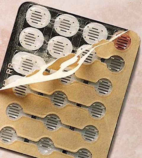
3.1 Flat-contact stack (text diagram)
Finger press
1. Graphic overlay (PET/PC grade, print, optional light emboss)
2. Overlay adhesive
3. Upper circuit / flat membrane switch contact (Ag/C on PET, or hybrid)
4. Spacer with key openings + vent features ← membrane switch spacer design
5. Lower circuit pads (pattern registered to openings)
6. Rear adhesive + optional shield / stiffener
7. Flexible tail + connector → host (debounce, LED, UI)
Enclosure land — flat support under each key
Optional modules (shield, LED layer, window, gasket) sit where the electrical and sealing plans require them—not as decoration. For general layer theory see sister construction resources such as a membrane switch layer-stack guide on the same site family; this article stays on non-tactile geometry decisions.
3.2 Step-by-step design and buyer process
Step 1 — Operator and environment map
List eyes-on vs eyes-off keys, gloves, noise, cleaning chemicals, and whether silence is required. If critical keys need snap confirmation, mark them tactile candidates before drawing flat art for the whole panel.
Step 2 — Key map and contact pattern
Draw every key, size, and pitch. Assign flat contact pattern class per key. Align pad centers to icons. Export a key map that mechanical, graphics, and circuit teams share.
Step 3 — Spacer and vent design
Dimension openings, thickness, webs, and vent path. Check seal plan against vent exits. Resolve conflicts before die tooling.
Step 4 — Overlay and support
Select film grade and emboss policy. Design enclosure lands under keys. If the stack needs a rear stiffener, add it to the BOM now.
Step 5 — Force, electrical, and feedback requirements
Write non tactile key force window, contact R / insulation targets, debounce ownership, and LED/UI/beep requirements. Link membrane button switches or related HMI parts only when the panel is a multi-technology assembly—not as a substitute for a missing force spec.
Step 6 — RFQ package
Send stack section, key map, spacer drawing, circuit art, material callouts, environmental needs, and sample quantities. Ask suppliers to confirm vent strategy and support assumptions in writing.
Step 7 — First-article on production-intent support
Mount samples on the real housing or a controlled fixture that matches land stiffness. Run continuity, force sampling, and operator trials with the real feedback path. Use quality / testing gates and, when life is contractual, name ASTM F1578-24 with the project load, rate, environment, endpoint, and inspection plan—not a bare cycle slogan.
3.3 Sample-approval / test matrix
| Check | What to run | Pass idea (project fills numbers) | Fail pattern |
|---|---|---|---|
| Visual / registration | Overlay vs pad vs opening | Centers within drawing tolerance | Icon off pad |
| Continuity | Each key closed / open | Meets contact R target when new | Open key, short between keys |
| Force sample | Force gauge on support fixture | Inside non tactile key force window | Soft corner keys, hard over voids |
| Operator trial | Task with real feedback | Miss rate acceptable | Users double-press constantly |
| Vent / feel consistency | Rapid press series | No progressive mush | Softens after air traps |
| Environmental (as required) | Temp, humidity, chemical wipe | Per product plan | Edge lift, contact drift |
| Life (if contractual) | ASTM F1578-24 cycling + project conditions | Agreed electrical and physical endpoint | Endpoint without method |
3.4 Drawing checklist — key map and support surface
Use this list before tool release:
- [ ] Key map with names, sizes, pitches, and critical vs non-critical roles
- [ ] Contact pattern class and pad sizes per key
- [ ] Spacer opening sizes, thickness, minimum web
- [ ] Vent path noted and compatible with seal claim
- [ ] Overlay material, finish, emboss yes/no
- [ ] Support land under each key on mechanical drawing
- [ ] Non tactile key force window + measurement fixture
- [ ] External feedback (LED / UI / beep / none) ownership
- [ ] Electrical targets (contact R, insulation, bounce/debounce)
- [ ] Tail/connector and rear adhesive callouts
- [ ] Mixed-zone dome map if any tactile keys exist
- [ ] Sample plan references production-intent support
4. When non-tactile is NOT the best choice — and release blockers
4.1 Choose another architecture when…
| Situation | Prefer instead | Why |
|---|---|---|
| Eyes-off critical start/stop | Tactile metal-dome keys | Snap confirmation without looking |
| Thick gloves, outdoor industrial | Higher-force tactile or other HMI | Flat soft keys disappear in gloves |
| No LED/UI/beep budget | Tactile or mechanical | Flat needs alternate feedback |
| Deep premium emboss as brand signature with snap feel | Tactile stack designed for emboss | Flat + deep emboss fights closure |
| Very small keys needing crisp event | Tactile dome sized to key | Flat force scatter rises on tiny pads |
| Safety-rated operator presence needs defined snap | Specified tactile or other switch class | Do not invent safety from flat membrane alone |
A flat stack remains strong for quiet rooms, wipe-down faces, simple mode keys, and panels that already show state on a display. It is a poor default for “every key on the machine” when some keys carry consequence.
4.2 Release blockers that disqualify a package
- No key map—only a pretty overlay JPEG.
- Spacer described as “standard holes” with no dimensions.
- Force left blank or “soft feel” without a window.
- First sample approved only as free film on foam.
- IP rating claimed from flat face with no enclosure test article (conflicts with IEC 60529 framing).
- Vent ignored on a perimeter-sealed design that samples mushy.
- Critical keys silent with no feedback plan.
- Domes added mid-project with no spacer/retainer redesign.
- Life guaranteed as a universal multiple of tactile without method (reject absolute competitor multipliers).
- Supplier refuses production-intent support fixture for force sign-off.
5. Frequently asked questions
What is non tactile membrane switch design in one sentence?
It is the engineering of a flat-contact membrane stack—contact pads, spacer openings, venting, overlay flex, and support—so keys close consistently without a snap dome, usually with LED, sound, or UI confirmation.
How does flat membrane switch contact differ from a metal dome?
Flat contact flexes an upper conductor through a spacer opening onto a lower pad. A metal dome adds a snap element that collapses at a design force and returns. Feedback, force curve, and BOM differ even when the overlay art looks identical.
What matters most in membrane switch spacer design?
Opening size and position relative to the pads, spacer thickness (open gap), web between keys, and any vent channels. Those four control accidental contact, travel, and much of the felt force.
What non tactile key force should a drawing specify?
There is no universal force number for a non-tactile key. Specify a project window from operator duty and accidental-press risk, then measure it on the selected overlay, spacer, circuit, actuator, and production-intent support. Glove use and deliberate actuation usually require different samples from frequent bare-finger entry.
Do non-tactile membrane switches need a vent?
Only when the finished contact pocket traps enough air to affect closure or return. Use repeat-press testing to confirm the mechanism, then route any vent to a controlled dry volume that remains compatible with the enclosure seal.
Can non-tactile panels be sealed to IP65 or IP67?
Sealing is an assembly and enclosure problem under IEC 60529, not a gift of flat graphics. Edge adhesive, tail exit, gasket, and vent routing decide liquid paths. An IP67 claim needs a defined enclosure and test article, not only a wipe-down PET face.
Is non-tactile always longer life than tactile?
Not as a universal rule. Removing a snap dome removes dome-specific failure modes, but life remains stack-, load-, environment-, and test-dependent. Name ASTM F1578-24 and the project conditions when life is contractual; avoid fixed multiplier claims taken from catalog blogs.
Should non-tactile keys be embossed?
Light rim emboss can help findability on a flat PC or PET overlay. Deeper emboss changes overlay flex and may raise force or increase missed presses. Decide emboss for location and cleaning, then re-check the force window on the real housing.
Can one panel mix tactile and non-tactile keys?
Yes, when the selected dome parts, spacer, graphics, actuator, and ASTM F1578-24 test conditions are designed together. Mixing without a co-designed stack creates registration and feel defects in both tactile and flat zones.
What package should a manufacturer receive for review?
Key map, stack section, spacer and circuit drawings, force and electrical targets (including contact R in ohms and insulation in MΩ), feedback plan, support land drawing, and sample quantities. Ask for review of the key map and support surface before tooling freeze on the JASPER or peer OEM line.
6. What to do next
Freeze the operator story first, then the geometry: flat membrane switch contact pattern, membrane switch spacer design, air path, overlay flex, and support land. Write the non tactile key force window and name the external feedback owner. Run first article on the housing that will ship. JASPER can review the key map and support surface as one implementation option; the framework does not depend on one vendor. For construction options see non-tactile membrane switches. For validation language see quality and testing.
Review the key map and support surface against the checklist in §3.4 before the next sample PO.
Review the key map before the spacer is released
Send the key map, circuit art, spacer opening map, overlay construction, force target, support-land drawing, environment, and feedback plan. JASPER Engineering will review the contact and support assumptions for the first sample.