
An EV charging station HMI panel is the complete user-facing hardware assembly, not merely an LCD. For public outdoor EVSE, specify the optical stack, touch or key input, cover and graphics, gasketed enclosure joint, payment-reader zone, electrical interfaces and service boundary as one system. The right construction depends on ambient light, solar and internal heat, rain or cleaning exposure, glove use, impact risk, accessibility, host architecture and replacement strategy. OEM teams should select targets from the charger’s installation and compliance plan, then validate a production-representative assembly. No single brightness, glass thickness or IP rating fits every charge station HMI panel.
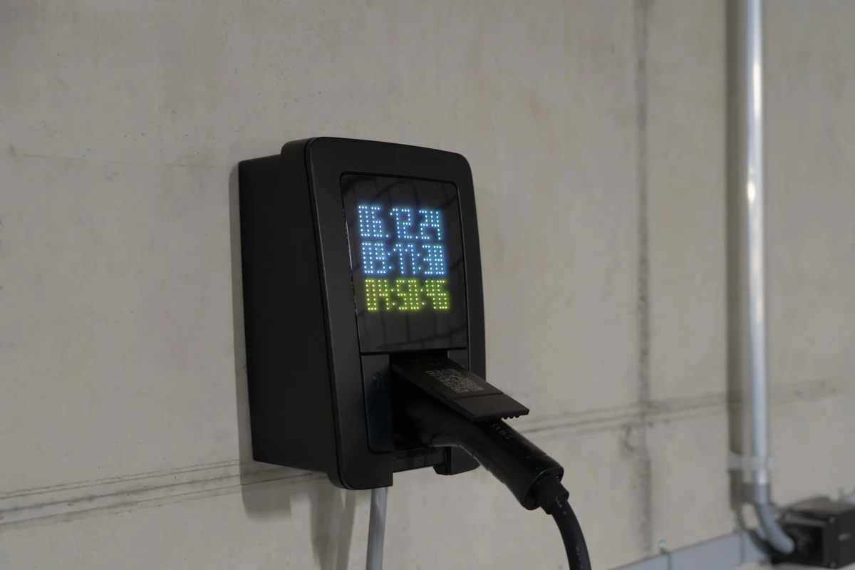
Quick decision: choose the HMI architecture from the use case
Use the smallest architecture that satisfies local interaction and service requirements. A larger computer or touchscreen cannot correct a poor optical stack, seal or interface contract.
| Architecture | Best fit | Hardware included at the panel | Main trade-off |
|---|---|---|---|
| Indicators plus hard keys | Simple wallbox or fleet charger | Overlay, LEDs, keys, flex circuit | Limited instructions and diagnostics |
| Display plus keys | Readable states with deterministic input | Display, window, sealed keys, interconnect | More apertures and labels to seal |
| Touch display peripheral | Graphics generated by a separate host | Display, touch, cover, bond, video/touch links | Host and two signal paths need ownership |
| Embedded HMI | Local application and input/output | Touch display, compute, memory, power, harness | Software image, heat and lifecycle enter scope |
| Industrial panel PC | Complex service or multi-application UI | Computer, display, touch, input/output and OS | Greatest depth, power and replacement burden |
Custom HMI assemblies can combine the cover, window, input circuit, gasket and interconnect. For foundational context, see What Is an HMI Panel? Hardware and OEM Guide.
A charge station HMI panel is an assembly, not just a screen
The HMI panel is the physical boundary between a user and the charger’s local control interface. It presents instructions, authorization, tariff, energy, payment, fault and recovery states supplied by a host. Front-panel hardware must do this without admitting water, generating false input or blocking service.
A typical touchscreen construction runs from outside to inside as follows:
- Surface: strengthened glass or durable film, with specified finish and cleaner compatibility.
- Graphics: printed border, overlay or labels defining active zones and warnings.
- Input: PCAP, resistive touch, membrane circuit, metal domes or discrete switches.
- Optical coupling: air gap, OCA or LOCA, selected for optics, stress and rework.
- Display: TFT LCD or another module with its backlight, FPC and driver boundary.
- Carrier: bezel or frame that avoids point loads on glass and LCD.
- Seal: controlled gasket/adhesive joint to the charger enclosure.
- Rear interfaces: power, video, touch, keys, LEDs, shielding and strain relief.
The drawing must assign every layer. “10-inch HMI screen” omits active area, viewing direction, cover outline, FPC exit, touch controller, video format, gasket surface and test boundary. Adapt the HMI Panel Assembly Design Checklist to the EVSE stack. IEC 61851-1 covers operating and safety requirements for EV supply equipment within its scope; it does not make the panel a standalone certified product.
Outdoor readability is an optical-stack and temperature decision
Outdoor readability depends on luminance, reflections, viewing angle, surface condition and UI contrast. A high backlight value alone is not a design rule. The same LCD changes behind untreated glass, anti-glare treatment, a bonded sensor or a deep bezel.
Record viewing direction, height, direct-sun duration, bright surroundings, shade and expected eyewear. Test normal screens, warnings, QR codes and tariff text. ISO 9241-303 gives technology-independent display image-quality guidance; the OEM defines the task and environment.
Optical bonding removes an internal air interface but changes stress, rework and material compatibility. 3M’s 817XCL OCA is one display-bonding example; its properties apply only to the named products. Approve the actual bond after optical, bubble, touch, temperature and repair checks.
Anti-reflective treatment targets specular reflection; anti-glare treatment scatters light and may add haze or sparkle. Corning’s treatment explanation shows why reflection and image clarity need joint review. An oversized printed border can also mask the image at oblique angles.
Solar load, dark paint, power electronics, backlight and local compute can push LCD, polarizer, adhesive and controller temperatures above ambient. Use component measurements from a powered enclosure, not only a module ambient rating.
IEC 60068-2-5 addresses simulated solar radiation, IEC 60068-2-14 temperature changes, and ISO 4892-3:2024 fluorescent-UV, heat and water exposure for plastic specimens. They answer different questions. A coupon result does not qualify the bonded panel, and accelerated hours are not field years without validated correlation.
Touch, water, gloves, impact and sealing must be specified together
PCAP touch can work behind unbroken glass, but performance depends on sensor geometry, controller, cover dielectric, grounding, display noise, firmware, liquid and glove. Name the glove material/thickness, gestures and water or cleaner condition.
Microchip’s EV charger touch page gives a bounded example: selected maXTouch families list cover glass up to 10 mm, thick-glove multi-finger input, liquid immunity, USB/I²C and IEC 61000-4-6 at 10 VRMS, Class A. Supplier conditions apply. These figures do not qualify a finished charger or another controller.
| Input choice | Strength | Failure concern | Engineering implication |
|---|---|---|---|
| PCAP touchscreen | Sealed glass and flexible controls | False/missed touch from water, glove, noise or ground | Approve firmware with production stack and liquids |
| Resistive touchscreen | Pressure input suits many gloves | Flexible surface, optical and wear limits | Verify force, surface, seal edge and readability |
| Membrane/discrete keys | Tactile, deterministic actions | More seal features and label wear | Define actuation, spacing, circuit tail and gasket |
| Display-only/remote action | No touch tuning | Phone, network or accessibility dependency | Preserve local status, help and recovery |
Water management must prevent ingress and unintended input. A protective lip can retain conductive liquid; a careless drain can open a rear path. Test droplets, running water, wet gloves and permitted cleaner at installed angles, including after aging.
Ratings belong to defined assemblies. IEC 60529 defines the enclosure IP Code; “IP65 glass” cannot rate seams, cable entries or connectors. IEC 62262 defines the enclosure IK Code. Select levels by risk, then test the agreed boundary and mounting.
Vandal resistance is not merely thicker glass. Protect edges, avoid fastener point loads, specify support span and define post-breakage retention. See Rugged HMI Design for Harsh Environments for related enclosure decisions.
Payment and accessible interface zones shape the front panel
Reserve payment, identification and help zones before freezing the cover. Contactless antennas need supplier keep-outs from metal, displays and cables. Readers need approach clearance and drainage. LEDs, audio, scanners and tamper seals compete for area; their service path should not disturb a bonded display unless intended.
For covered U.S. federal charging projects, 23 CFR 680.106 requires accessible secure payment and, unless charging is permanently free, contactless major debit/credit cards plus toll-free phone or SMS initiation/payment. It is not a rule for every private charger. EMV or PCI approval belongs to the selected payment architecture, not the printed panel.
The U.S. Access Board EV guide separates binding ADA, ABA and Section 508 provisions from nonbinding recommendations. Federal-agency charger ICT must meet Section 508. Cited hardware provisions include viewing from 40 inches above clear floor/ground, no flashing above 3 flashes per second, and adjustable text or at least 3/16-inch characters. Tactile controls, non-color cues, speech and visual/audible payment feedback also affect hardware.
Start mechanics from reachable operable-part zones and the intended approach. Where risk analysis requires an independently identifiable safety action, separate it from screen navigation. Window, labels, key geometry, speaker opening, tactile marker and reader mounting remain hardware responsibilities.
Communications are four different interfaces, not one feature
An embedded HMI for EV chargers sits between the panel and charger controller. Distinguish video, touch, local control and external network links; “Ethernet HMI” or “OCPP ready” hides ownership.
| Boundary | Typical examples | Hardware owner must define | What it does not prove |
|---|---|---|---|
| Host to display | LVDS, eDP, MIPI DSI, RGB | Timing, rails, startup, cable, backlight | Touch or application compatibility |
| Touch to host | USB HID or I²C HID | Driver, interrupt, firmware, ground | Video or wet/glove behavior |
| HMI to charger control | UART, CAN, Ethernet, input/output | Messages, isolation, timeout, safe state | Backend interoperability |
| Charger to management | OCPP/network stack | Version, security, certification, backend | Panel capability |
| EV to EVSE control | ISO 15118 family | EVCC/SECC and charging integration | Local display interface |
Texas Instruments TIDEP-0087 makes the separation concrete: its 2017 reference uses a 4.3-inch 480 × 272 LCD, resistive touch and AM335x options with UART/CAN. It is an example, not a required architecture.
The Open Charge Alliance defines OCPP as station-to-management-system communication. OCPP 1.6, 2.0.1 and 2.1 are distinct; a raw display is not OCPP-compatible. ISO 15118-20 covers EVCC-to-SECC communication. A local HMI may present their states, but both boundaries sit beyond display manufacturing.
See Industrial HMI Communication Protocols and Hardware Interfaces for connector ownership. JASPER can manufacture defined panel circuits, flex tails and harness interfaces; PLC/SCADA code, OCPP stacks and charger programming are out of scope.
The application-risk matrix should drive the construction
Do not copy one stack across a shaded depot, highway DC fast charger and residential wallbox. Convert installation facts into assembly decisions.
| Application condition | Likely panel failure path | Design response | Evidence required before release |
|---|---|---|---|
| Direct sun, dark enclosure | Washed image, hot polarizer/adhesive, graphic fade | Control reflection, heat path, brightness and UV materials | Stack readability; powered solar/thermal test; color/adhesion check |
| Rain, washdown or road residue | Seal bypass, false touch, connector corrosion | Continuous seal, controlled compression, drainage, wet tuning | Ingress plus wet-input/cleaner tests before and after aging |
| Cold use with gloves | Missed input, brittle cable or seal | Name glove; enlarge targets; consider keys | Glove matrix and temperature-change function |
| Public curbside use | Edge break, prying, ESD, reader tampering | Supported edge, recessed fasteners, ESD path | IK/impact and IEC 61000-4-2 plans; post-test seal/function |
| Federal/public payment | Unreachable reader or visual-only status | Set reach/view first; tactile and audiovisual cues | ADA/ABA/Section 508 and 23 CFR 680.106 scope review |
| Multiple service revisions | Wrong cable, tuning file or LCD | Keyed connectors, labels, controlled BOM/firmware | Replacement trial and interchangeability record |
Trace the path, not just the symptom. A “dead touchscreen” may mean surface water, shifted ground, converter noise, a loose USB cable, wrong firmware or a failed host. Fog may indicate internal humidity, bond void, seal leak or temperature cycling. Prototype diagnostics should isolate each interface.
Validation must use a production-representative panel and enclosure
Validation advances from material coupons to the complete powered charger. A desktop LCD cannot qualify the cover, bond, touch tuning, gasket and enclosure joint.
| Standard or method | Question it can answer | Specimen and acceptance input |
|---|---|---|
| IEC 60529 | Selected solids/water exposure at the enclosure boundary? | Panel with production seal, fasteners, connectors and enclosure |
| IEC 62262 | Selected external impact at the enclosure? | Mounted panel; inspect safety, seal and function afterward |
| IEC 60068-2-5 | Effect of simulated ground-level solar radiation? | Defined assembly, surface, orientation and post-test checks |
| IEC 60068-2-14 | Effect of specified temperature changes? | Bonded display, gasket, tails and connectors under function |
| IEC 60068-2-78:2025 | Effect of non-condensing damp heat? | Product-selected specimen, severity and duration |
| ISO 4892-3:2024 | UV/heat/water effect on plastics? | Production overlay, ink or coating coupons |
| IEC 61000-4-2:2025 | Response to operator/nearby-object ESD? | Powered charger; product-selected points and criteria |
| IEC 61851-21-2 | Applicable EMC for off-board charging equipment? | Complete EVSE in defined modes |
| ISO 9241-303 | Defined electronic-display image quality? | Complete optical stack at task/environment |
NEMA Types and IEC IP codes are not interchangeable labels. NEMA’s enclosure FAQ says IP ratings do not substitute for enclosure Type ratings in U.S. installations. State the required scheme and evidence.
Use five gates: material coupons; display/touch stack; representative enclosure; testing and validation planning against released criteria; then a frozen golden sample, BOM, touch configuration, display timing, cable and inspection method.
Prototyping and sample approval should cover cold/warm starts, sleep, brownout, network loss, safe cable interruption, wet/glove input, maximum brightness and charger-power operation. Record instrument, distance, angle and ambient condition.
Serviceability and configuration control belong on the drawing
Choose the field-replaceable unit: HMI cartridge, display/touch stack, compute board or panel PC. This fixes connector access, fastener direction, cable slack, gasket, calibration and inventory. Bonding may improve optics yet block glass-only repair; an air gap eases window service but adds reflection and contamination risk.
Drawings need active/viewing areas, border, touch outline, glass edge, cosmetic zones, gasket land, fastener/compression control, datums, tail exit, bend radius, keep-outs and rear height. Pair each LCD revision with timing, backlight, touch firmware, host driver and cable.
A touchscreen is unsuitable when local interaction cannot justify its environmental and service burden. A plug-and-charge wallbox may need only status indicators and one control; an impact-prone charger may favor a small protected display plus keys. Phone-only flow still needs compliant local status, help and recovery.
Frequently asked questions
What does a charge station HMI panel include?
A charge station HMI panel includes the cover or overlay, graphics, display window, touch or keys, circuit, indicators, bond, carrier, gasket and rear interfaces. An embedded version may include compute. Charger control, OCPP software and power electronics stay separate unless the agreement explicitly includes them.
How bright should an outdoor EV charger display be?
No universal luminance value fits every charger. Specify readability at worst ambient light, viewing angle and surface condition, then test the complete display, touch, cover and treatment stack. More backlight may help but raises power and temperature; reflection and UI contrast remain decisive.
Is optical bonding required for an EV charging station touchscreen?
Optical bonding helps when internal reflection, air-gap contamination or stack integration justifies it; it is not automatically required. It reduces rework and adds adhesive, stress and process dependencies. Approve the actual LCD, sensor, cover, bond and edge support through optical, thermal, humidity and touch tests.
Can projected-capacitive touch work through rain and gloves?
Yes, a selected and tuned PCAP system can support specified liquids and gloves, but capability is controller- and stack-specific. State glove, cover, fluid, gesture and noise conditions. Validate production glass, sensor, firmware, grounding, display and harness together; reject a generic “wet and glove touch” label.
Does an IP65 display make the complete charger IP65?
No. IEC 60529 applies an IP code to a defined enclosure boundary. The charger also has panel seals, fasteners, doors, cable entries, payment hardware and connectors. Evaluate the intended assembly at the selected boundary; a component claim cannot establish every surrounding joint.
What is the difference between an embedded HMI and a panel PC for EV chargers?
An embedded HMI combines display, touch and purpose-defined local compute. A panel PC is a general industrial computer with enclosure, operating system and external input/output. It may shorten integration, but usually adds depth, heat, power and replacement cost.
Does the HMI display need OCPP support?
The raw display does not need OCPP. OCPP connects the station to a charging management system in the software/network domain. The local HMI may show derived messages, tariffs or status, while video, touch and controller links remain separate. Put the OCPP version in the charger software specification.
What information should an EV charger HMI RFQ include?
Include the panel drawing; display area/interface; cover/graphics; touch or key conditions; enclosure seal; ambient and component temperatures; solar/UV, liquid, glove, impact and accessibility targets; payment keep-outs; host boundary; cable/connector details; validation methods; annual volume; and service strategy.
Project-input checklist for engineering review
Before the RFQ, collect the following:
- charger type, region and orientation;
- display area, resolution, viewing distance and critical screens;
- panel/enclosure drawing, gasket land and fasteners;
- cover, finish, graphics, cosmetics and cleaners;
- touch, named gloves, water and gestures;
- host, video, touch, power and backlight interfaces;
- payment/NFC, scanner, audio, LED and safety-control keep-outs;
- thermal, solar, UV, humidity, ingress, impact, ESD and EMC targets;
- reach, viewing, tactile, audible and non-color requirements;
- service boundary, configuration control and annual volume.
OEM teams can send drawings for engineering review with the display size, front-panel drawing, interface stack, environment and annual volume. When those inputs are defined, request an engineering quote for the manufacturable HMI assembly rather than an unspecified “outdoor screen.”
Apply the cited standards and component examples within their stated scopes. Verify the HMI assembly and charging equipment against the requirements assigned to the finished product.
References
- IEC, IEC 61851-1:2017 EVSE general requirements and IEC 61851-21-2:2018 off-board EVSE EMC.
- IEC, IEC 60529 IP Code and IEC 62262 IK Code.
- IEC, IEC 60068-2-5:2018 solar radiation, IEC 60068-2-14:2023 temperature change and IEC 60068-2-78:2025 damp heat.
- IEC, IEC 61000-4-2:2025 ESD immunity.
- ISO, ISO 4892-3:2024 plastics UV exposure, ISO 9241-303:2011 electronic displays and ISO 15118-20:2022 EV–EVSE communication.
- U.S. Access Board, Accessible EV Charging Stations.
- eCFR, 23 CFR § 680.106, current through August 20, 2026 when researched.
- Open Charge Alliance, OCPP versions and scope.
- Microchip Technology, EV Charger Touch Solutions.
- Texas Instruments, TIDEP-0087 EVSE HMI Reference Design.
- NEMA, Enclosure Type and IP FAQ.
- 3M, Optically Clear Adhesive 817XCL Series.
Bring the drawing, stack and operating conditions
JASPER engineering will review the interfaces, open risks and evidence required for a production quote.