
Force sensing resistor vs strain gauge selection for a thin seat turns on the measurement job. Start with an FSR for a low-profile, distributed presence or relative-load layer when the complete contact stack can be controlled and calibrated. Start with a strain-gauge load-cell assembly when calibrated absolute load and a defined structural path matter more than packaging simplicity. Neither sensing element decides vehicle performance by itself: foam, preload, contact area, mounting, electronics, temperature, calibration, and system validation set the result. This comparison helps seat-system teams choose a prototype architecture; it does not confer component or vehicle approval.
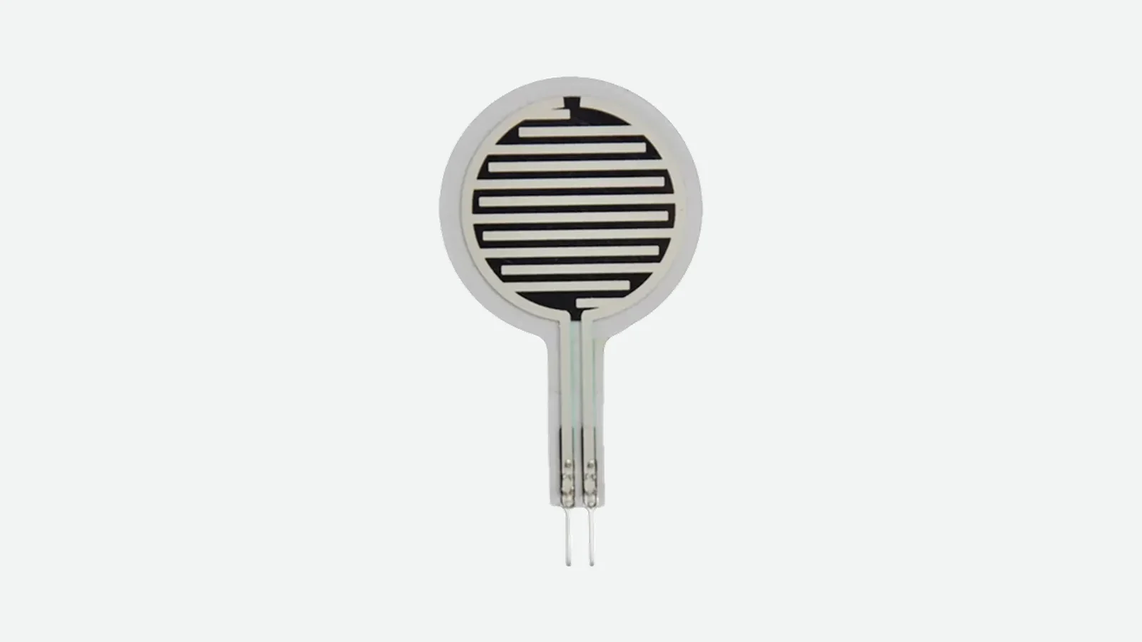
Quick Verdict: Which Technology Starts Ahead?
The starting architecture depends on load-path control and whether the output is a state, relative signal, or calibrated force.
| Decision dimension | FSR assembly starts ahead when… | Strain-gauge load-cell assembly starts ahead when… |
|---|---|---|
| Required output | Presence, threshold, or relative load is sufficient | Absolute force or weight is required |
| Load path | Load arrives through a controlled contact patch or distributed cushion stack | Load can be routed through a defined elastic member or seat mount |
| Package | The sensing layer must conform to a thin or flexible region | A rigid load-introduction feature and several millimeters of local height are acceptable |
| Linearity | A lookup table or threshold model is acceptable | A more linear force-to-output relationship is a primary requirement |
| Static dwell | Drift can be characterized and allowed for in the decision margin | Long-term static-force stability has a tight error budget |
| Electronics | A divider, comparator, or op-amp readout fits the function | Bridge excitation, instrumentation gain, and differential conversion are available |
| Calibration | The complete contact stack can be conditioned and calibrated | The transducer, readout, mounting, and force path can be calibrated as a controlled system |
| Spatial information | Several thin zones or a distributed layer are useful | Total force at one or more structural points is the useful measurement |
| Program risk | Foam, actuator, support, and threshold ownership are clear | Spring element, fasteners, off-axis load, overload, and calibration ownership are clear |
Neither route owns cost or package size by default. Compare the installed BOM, calibration, production checks, and validation scope.
Force Sensing Resistor vs Strain Gauge: Compare Complete Measurement Chains
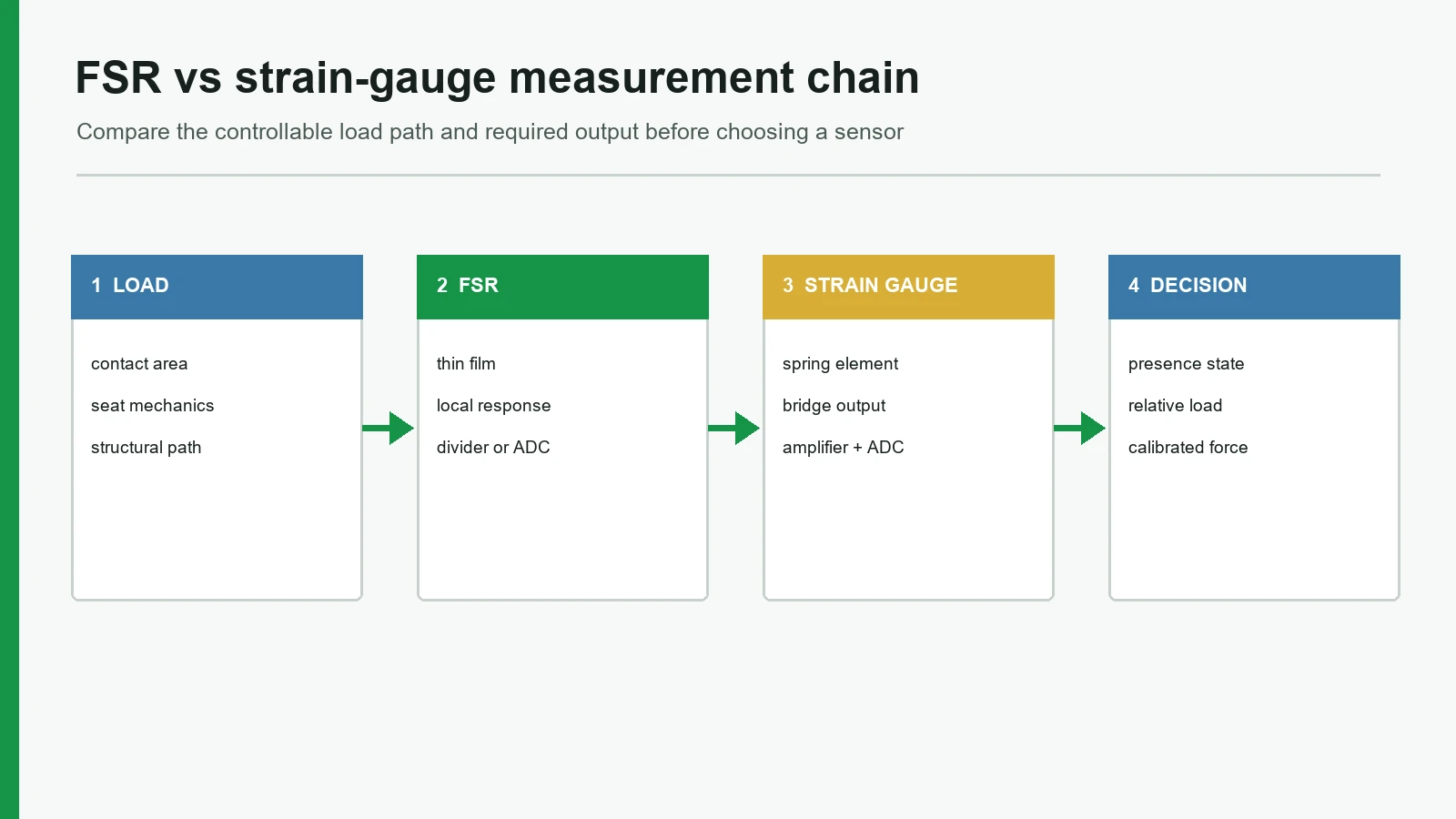
A valid force sensing resistor vs strain gauge comparison pairs an FSR assembly with a strain-gauge transducer assembly. A loose strain gauge is only a resistance element that follows deformation; it does not become a force sensor until an elastic member, gauge placement, bridge, electronics, mounting, and calibration establish a force-to-output relationship.
Interlink describes its FSR 400 Series as two-wire devices whose response depends on applied force, actuation mechanics, sensor geometry, and measurement electronics in the FSR 400 Series Data Sheet. NI defines a bonded metallic strain gauge and its gauge factor, then shows why the small resistance change is normally read through a Wheatstone bridge in Measuring Strain with Strain Gages.
Thin FSR sensing assembly
seat occupant or test load
trim / foam / load spreader
FSR active area + backing
resistance or conductance
divider, comparator, or op-amp + ADC
conditioned threshold or calibrated estimate
Strain-gauge load-cell assembly
seat occupant or test load
seat frame / mount / load-introduction hardware
controlled elastic member
bonded gauges in a Wheatstone bridge
excitation + instrumentation amplifier + ADC
calibrated force or classification input
This boundary changes the familiar FSR vs load cell question: the FSR's contact stack is part of its transfer function, while the strain-gauge route places that function in a designed structural member.
Side-by-Side Specifications Under Stated Conditions
These representative datasheets are not a common benchmark. Interlink, Tekscan, and Honeywell use different ranges, circuits, conditioning, and definitions.
| Representative device | Thickness or height | Published force range | Published performance examples | Signal chain and critical condition |
|---|---|---|---|---|
| Interlink FSR 400 | 0.30 mm nominal bare sensor | About 0.2–20 N typical | ±2% single-part repeatability; ±6% part-to-part within one batch; about 10% average hysteresis; drift below 5% per log10(time) at 1 kg over 35 days | Two-wire resistance; most specifications derive from 1,000 g tests; actuator, mechanics, and electronics affect response |
| Tekscan FlexiForce A201 | 0.203 mm bare sensor | Approximate 4.4 N, 111 N, or 445 N versions | Linearity error below ±3% FS from 0–50% load; repeatability below ±2.5% and hysteresis below 4.5% FS on a conditioned sensor at 80% full force; drift below 5% per logarithmic time at constant 111 N | Typical data use an op-amp circuit; drive voltage and feedback resistance can alter the usable range |
| Honeywell Model 13 family | 3.3 mm for 150 g–50 lb variants; 3.81 or 6.35 mm for higher ranges | 150 g–1,000 lb family; bonded foil from 1,000 g upward | ±0.5% FS nonlinearity; ±0.5% FS hysteresis; ±0.1% FS non-repeatability | Compression load cell with mV/V output; family includes semiconductor and bonded-foil variants, an elastic diaphragm, cable, and balance module |
Sources: Interlink FSR 400 Series, Tekscan FlexiForce A201, and Honeywell Model 13.
The table is not a category ranking. Every number keeps its model and condition. Model 13 is not a seat-qualified product or JASPER specification.
Where an FSR Assembly Wins
An FSR assembly starts ahead when the seat needs a thin sensing zone and the useful output is presence, a threshold, or relative load rather than traceable occupant weight.
1. The sensing element can sit inside a thin, compliant stack
Interlink lists 0.30 mm nominal thickness for Model 400; Tekscan lists 0.203 mm for A201. Both can begin a design inside trim or foam where a rigid body would disrupt the package. Bending must not create preload or trace damage.
That advantage belongs to the sensing element, not the finished assembly. Interlink's integration guide says support, curvature, shear, venting, and adhesive can change response. The seat drawing must include the spreader, backing, protection, tail exit, and strain relief.
2. Several zones can preserve useful spatial information
A set of FSR zones can preserve location information for presence logic, relative left-right loading, or a coarse pressure profile. It still needs channel matching, cross-talk checks, foam-aging tests, and an assembled-seat model. A single zone receives only part of occupant load; posture, foam, trim, seat angle, and bypass paths change that share.
3. Threshold readout can be electrically compact
For a presence threshold, a divider, comparator, or ADC channel may be enough. Interlink documents divider and current-to-voltage circuits; component values set the useful span. Diagnostics still need open, short, stuck, and implausible-state detection.
The FSR route is not best for a narrow absolute-force error budget across dwell, environment, replacement, and changing contact geometry. A thick precision actuator or heavy per-unit calibration can also erase its package advantage.
Where a Strain-Gauge Load-Cell Assembly Wins
A strain-gauge load-cell assembly starts ahead when the seat structure can route load through a controlled elastic member and the program needs calibrated absolute force with lower nonlinearity and hysteresis under stated conditions.
1. The force path can be designed into the structure
HBK describes a strain-gauge force transducer as a spring element carrying gauges at selected strain locations in Force Transducers Based on Strain Gauges. The spring element converts the applied force into reproducible strain; the bridge converts the resulting resistance changes into a differential voltage.
This moves the transfer function into a structural part. Controlled mounts and load-introduction points can make total force more predictable than local film response under changing foam contact.
2. Product-level linearity and repeatability can be specified
The Honeywell Model 13 example lists ±0.5% FS nonlinearity, ±0.5% FS hysteresis, and ±0.1% FS non-repeatability for its family. Those values are not universal strain-gauge properties; they belong to a completed diaphragm transducer with a specified bridge, cable, balance module, range, and mounting geometry.
A bare gauge can be extremely thin, yet it has no force range until the elastic body is defined. Alloy, backing, adhesive, orientation, substrate, wiring, and protection remain design inputs in the Micro-Measurements Strain Gage Sensor Reference Guide.
3. Calibration can attach to a controlled measuring chain
Calibration does not cancel side load, uneven fasteners, cable force, frame contact, or load bypass.
The strain-gauge route is not best when the seat cannot direct load through the elastic member, local distribution matters more than total force, or mounts and rigid clearance conflict with the architecture.
Thin Pressure Sensor Comparison: Bare Thickness Is Not Installed Height
For this article, a thin pressure sensor comparison means contact load at the seat interface, not pressure in a gas or liquid line. The correct package comparison includes every layer that transfers load or protects the signal.
Tekscan's A201 is 0.203 mm thick, but Tekscan's catalog load concentrator is 0.7 mm thick. Those two items alone total 0.903 mm before adhesive, cover film, shear isolation, backing, foam, tail routing, or manufacturing tolerance. A compact load cell can also be thinner than the common “bulky load cell” shorthand: the named Honeywell Model 13 examples begin at 3.3 mm high, before their loading and mounting features.
| Installed layer or function | Thin FSR assembly | Strain-gauge load-cell assembly |
|---|---|---|
| Load introduction | Foam, trim, puck, boss, or spreader controls contact area | Button, seat rail, bracket, or mount routes force into the elastic member |
| Sensing body | Printed resistive element; 0.203 mm A201 and 0.30 mm FSR 400 are named bare examples | Gauge plus elastic body; 3.3 mm Model 13 is one named compact example |
| Support and protection | Flat backing, adhesive, cover, vent path, tail strain relief, shear isolation | Fasteners, bearing surfaces, side-load control, stops, cable strain relief, environmental seal |
| Electronics | Divider/comparator for a threshold, or op-amp and ADC for a wider calibrated span | Stable excitation, bridge completion where needed, instrumentation amplifier, ADC, zero/span correction |
| Calibration object | Preferably the finished sensor/contact/foam/support stack | Transducer plus readout and, when installation effects matter, the released mounting stack |
| Service change | Foam, cover, adhesive, actuator, or sensor replacement can shift the transfer function | Load cell, fastener, bracket, cable, amplifier, or seat-frame replacement can shift zero or span |
Total cost needs a defined scope
No method-equivalent public prices support a universal winner. Compare the sensor, mechanics, electronics, calibration fixture and cycle time, production test, scrap, replacement, change qualification, and vehicle validation. A low-cost film can demand expensive sorting; a costlier transducer can require difficult mounting. Either pattern can reverse by project.
Accuracy is an error budget, not a label
The required output defines the error budget: thresholds need classification margin, relative maps need channel stability, and force values need uncertainty and traceability.
| Error source | FSR assembly: first variables to test | Strain-gauge assembly: first variables to test |
|---|---|---|
| Load introduction | Contact area, position, hardness, foam spread, trim tension, shear | Eccentricity, side load, bending moment, bearing surface, fastener torque |
| Mechanical response | Foam and adhesive creep, backing stiffness, preload, housing bypass | Spring geometry, material state, mounting strain, stops, structural bypass |
| Sensor behavior | Part variation, nonlinearity, hysteresis, conditioning, resistance drift | Gauge factor, bond, bridge balance, transverse sensitivity, creep |
| Environment | Humidity, temperature, foam stiffness, adhesive behavior | Gauge/substrate thermal match, bridge zero, modulus change, moisture protection |
| Electronics | Divider selection, op-amp gain, leakage, ADC range, open/short detection | Excitation, amplifier offset and drift, lead resistance, shielding, ADC range |
| Calibration | Fixture/contact mismatch, limited points, load rate, dwell, replacement policy | Force standard, mounting, orientation, readout pairing, interpolation, zero procedure |
| Time and change | Dwell, recovery, wear, foam aging, stack revision | Creep, zero return, overload history, fastener settling, bracket revision |
The error budget prevents a common mistake: using a datasheet repeatability value as total system accuracy. Interlink's ±2% FSR figure is a same-part repeatability result under a repeatable actuation system; Tekscan's A201 figures require conditioning and a stated load point; Honeywell's numbers belong to a completed Model 13 transducer. None represents an assembled vehicle seat without validation.
Which Seat Sensor Technology Fits the Measurement Job?
Seat sensor technology should be selected from the required output and controllable load path, not from a generic accuracy ranking.
| Measurement job | Better starting point | Decision boundary |
|---|---|---|
| Thin occupied/unoccupied threshold inside a cushion | FSR assembly | Use only if contact area, preload, foam, temperature, dwell, and threshold margin can be controlled |
| Several relative load zones for coarse posture or load distribution | FSR zones or a pressure-mapping array | A few FSRs do not create a calibrated pressure image without spatial calibration |
| Total load measured through controlled seat mounts | Strain-gauge load-cell assembly | Every significant load path must pass through the measuring elements without structural bypass |
| Calibrated absolute force with a traceable bench chain | Strain-gauge load-cell assembly | Installation, amplifier, temperature, orientation, and readout pairing remain part of the result |
| Simple open/closed occupancy state | Neither analog route may be necessary | A contact-type membrane sensor can be a cleaner architecture if analog load adds no value |
| Full interface-pressure distribution | Neither a single FSR nor a single load cell | Use a calibrated pressure-mapping array designed for spatial data |
| Adult/child/object/posture classification | Neither sensor alone should be assumed sufficient | Classification may require multiple zones, seat geometry, belt inputs, cameras, capacitive sensing, or sensor fusion |
| Seat structure cannot provide repeatable contact or structural load introduction | Neither | Redesign the load path or select a sensing principle that tolerates the available mechanics |
For automotive seat applications, a sensor output is only one system input. The applications overview provides broader context; the vehicle manufacturer and system integrator own behavior and vehicle evidence.
NHTSA's Interpretation 22492 says the agency does not approve commercial sensors and the vehicle manufacturer self-certifies. A component is therefore not “FMVSS 208 certified.” 49 CFR §571.208 sets vehicle performance; it does not select a sensor principle.
Validate the Seat, Not Just the Sensor
A useful validation plan exercises the released seat stack, mounting, electronics, software, and change limits. Bench data on a loose sensor is screening evidence, not release evidence.
A 2026 NHTSA recall report 26V180 describes seat-frame/stopper interference that caused an occupant-classification system to mismeasure load. It does not identify the sensor principle, but it shows how structure and tolerance can corrupt the complete path.
| Test block | Controlled input and condition | FSR assembly: observe | Strain-gauge assembly: observe | Minimum release evidence |
|---|---|---|---|---|
| Load position and contact | Center, edge, front, rear, asymmetric posture, representative fixtures | Zone transfer, bypass, active-area alignment, foam spread | Load sharing, eccentricity, side load, moment, mount contact | Raw signals, classification result, fixture drawing, position map |
| Loading and unloading | Multiple points approached from both directions | Hysteresis, threshold-on and threshold-off margin | Hysteresis, reversibility, zero return | Up/down curves and acceptance bands |
| Static dwell and recovery | Empty, preload, nominal loads, maximum service dwell, unload recovery | Resistance drift, foam/adhesive creep, recovery time | Creep, zero shift, fastener settling, amplifier drift | Time series and allowed decision drift |
| Temperature and humidity | Released operating and storage profiles at loaded and unloaded states | Sensor, adhesive, foam, leakage, threshold shift | Bridge zero/span, thermal match, modulus, mounting constraint | Conditioned before/after data and recovery criteria |
| Assembly tolerance | Foam density, trim tension, adhesive, spreader, sensor location, bracket, torque | Contact repeatability and preload distribution | Mounting strain, load bypass, load-sharing balance | Tolerance matrix linked to drawings and process controls |
| Shear and off-axis load | Seat adjustment, ingress/egress, lateral load, cable motion | Layer slip, delamination, tail damage, false actuation | Side-load sensitivity, cable force, bracket deflection | Fault signature and damage inspection record |
| Overload and impact | Defined misuse and shock pulses; mechanical stops active | Permanent resistance/curve change, puncture, crease | Zero/span change, spring-element or stop damage | Reject/retest rule and post-event diagnostic |
| Electrical faults | Open, short, leakage, loss of excitation, ADC rail, connector intermittency | Implausible resistance or transition | Bridge imbalance, excitation fault, amplifier saturation | Diagnostic coverage and safe-state behavior |
| Production and replacement | Multiple lots, build stations, seats, replacement parts | Part/stack spread and coefficient policy | Transducer/mount spread and recalibration policy | Statistical acceptance, traceability, change trigger |
| Vehicle-level classification | Applicable dummies, occupants, objects, belt and seat states | Final algorithm result, not component voltage alone | Final algorithm result, not force value alone | OEM-approved system test under applicable market requirements |
ASTM E74-18(2026) covers static force-instrument calibration and excludes high-speed work. ISO 376:2011 covers force-proving instruments for uniaxial testing machines. Neither qualifies a seat or vehicle.
Project Input Checklist Before Technology Selection
A measurement contract should define the result, calibrated object, and changes that trigger new evidence.
- Output: occupied state, relative band, zone map, calibrated force, or classification input.
- Load cases: minimum, normal, maximum, preload, overload, rate, impact, dwell, and unloading sequence.
- Geometry: contact area, foam and trim stack, load spreader, seat frame, mounts, fasteners, bypass paths, and permitted compliance.
- Package: allowable layer thickness, rigid height, tail or cable path, connector, service access, and replacement method.
- Environment: operating/storage temperature, humidity, fluids, contamination, vibration, adjustment cycles, and conditioning sequence.
- Electronics: excitation, divider or bridge, amplifier, ADC, sampling, filter, diagnostics, power state, and fault response.
- Calibration object: loose sensor, subassembly, finished seat, transducer/readout pair, each serial number, or controlled family.
- Production evidence: drawing tolerances, incoming checks, end-of-line test, coefficient storage, lot traceability, and change notification.
- System evidence: applicable vehicle requirements, occupant/object set, belt states, seat positions, algorithm version, and acceptance margin.
JASPER's current routes. Its testing and validation planning page links requirement, specimen, method, result, and acceptance. A prototype review should settle the load path before geometry or coefficients are frozen.
To choose the sensing technology, send the measurement job, seat cross-section, load path, electronics, environment, calibration object, and validation matrix through the project contact route. JASPER can assess an FSR path; a load-cell path needs a scope that owns the elastic member, bridge, mounting, and calibration.
Frequently Asked Questions
Is an FSR more accurate than a strain gauge?
No category-level accuracy figure answers that question. FSR results depend heavily on contact mechanics and calibration; a strain gauge has no force accuracy until it becomes a calibrated transducer. Compare installed error budgets under the same loads, temperatures, dwell, and mounting.
Is an FSR the same as a load cell?
No. An FSR is a force-sensitive resistive element read through a resistance-measurement circuit. A load cell is a complete force transducer with a mechanical load path, sensing elements, electrical output, mounting rules, and calibration.
Can an FSR measure occupant weight?
An FSR can estimate force after in-system calibration, but one seat zone receives only part of occupant load. Foam, posture, contact area, preload, and time alter that share. Use a complete-seat error budget before specifying weight accuracy.
How thick is an FSR compared with a load cell?
Named bare examples are 0.203 mm for Tekscan A201 and 0.30 mm for Interlink FSR 400. Honeywell Model 13 variants begin at 3.3 mm. Compare finished stacks, because spreaders, supports, mounts, wiring, and protection add height.
Which electronics are required for an FSR vs a strain-gauge load cell?
An FSR may use a divider or comparator for a threshold, or an op-amp and ADC for a calibrated span. A strain-gauge load cell normally needs bridge excitation, differential amplification, conversion, zero/span handling, and diagnostics.
How should a seat FSR be calibrated?
Condition and calibrate it in the released contact, foam, support, circuit, and environment, using service-representative loads, rates, dwell, and positions. Tekscan recommends matching the calibration and test environments.
What causes drift in a seat sensor?
FSR drift can include the resistive element, foam, adhesive, preload, humidity, and electronics. A strain-gauge system can drift through the spring element, bond, mounting, bridge, amplifier, or temperature. Record raw signals before changing calibration.
Which seat sensor technology should an OEM prototype first?
Prototype an FSR first for a thin presence or relative-load layer with controlled contact. Prototype a strain-gauge load-cell assembly first for absolute load through a controlled structure. Prototype another architecture if neither load path is repeatable.
Technical References
- Source: NIST force and calibration guidance. Accessed 2026.
- Source: ASTM E74 force-measuring instrument calibration. Accessed 2026.
- Source: ISO 376 force-proving instruments. Accessed 2026.
- Source: Interlink FSR 400 Series technical data. Accessed 2026.
- Source: NI strain gauge measurement guidance. Accessed 2026.
- Source: FSR 400 Series Data Sheet. Accessed 2026.
- Source: Measuring Strain with Strain Gages. Accessed 2026.
- Source: Interlink FSR 400 Series. Accessed 2026.
- Source: Tekscan FlexiForce A201. Accessed 2026.
- Source: Model 13. Accessed 2026.
- Source: integration guide. Accessed 2026.
- Source: Force Transducers Based on Strain Gauges. Accessed 2026.
- Source: Micro-Measurements Strain Gage Sensor Reference Guide. Accessed 2026.
- Source: Calibration of Force Transducers. Accessed 2026.
- Source: load concentrator. Accessed 2026.
- Source: Interpretation 22492. Accessed 2026.
- Source: 49 CFR §571.208. Accessed 2026.
- Source: NHTSA recall report 26V180. Accessed 2026.
- Source: E74-18(2026). Accessed 2026.
- Source: ISO 376:2011. Accessed 2026.
Choose the sensing chain from the measurement job
Send the required output, load path, package, electronics, environment, calibration object, and production evidence.