
Use this 10-input ECG electrode patch design guide to define geometry, skin interface, connections, packaging, and finished-device validation boundaries.
1. Why incomplete ECG patch inputs fail as a system
An ECG patch is a chain of mechanical, electrochemical, electrical, packaging, and user interfaces. A clean print can still produce unusable system data if the patch moves on skin, the lead vector is wrong, the gel changes during storage, or the tail transfers strain into a narrow trace. Supplier review therefore needs more than an outer die line and a preferred adhesive.
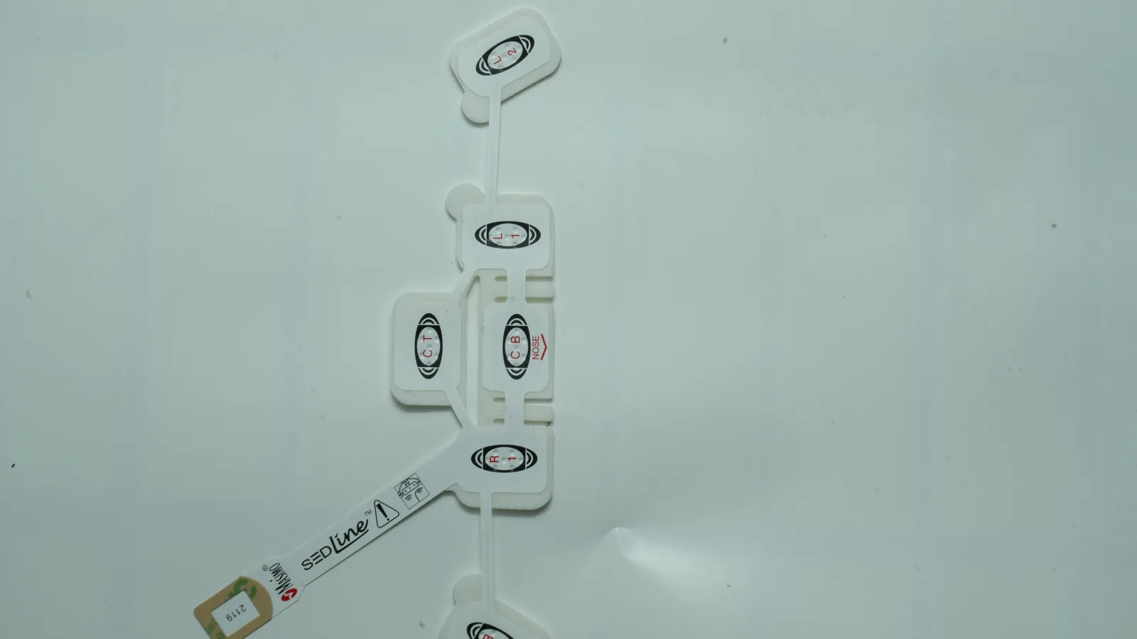
Three terms must stay separate. A physical electrode is a body-contact site. An ECG lead is the electrical view derived from electrode potentials. An acquisition channel is the hardware and data path that records a signal. Electrode count, lead count, and channel count may differ, so the drawing must map each contact to its electrical function and recorder input.
They are not interchangeable.
Published dimensions are examples, not defaults. A 2022 study evaluated one bipolar VitalPatch construction with a 7.8 cm inter-electrode distance in 30 subjects; the authors also identified form factor, placement, distance, orientation, materials, and electrode-to-body movement as factors that can change signal characteristics. The researchers were affiliated with the device manufacturer, and the analysis used selected high-quality stationary segments. That work supports device-specific validation—not a universal 7.8 cm rule. See Rajbhandary et al., 2022.
The same caution applies to mechanics. In a controlled study, Cömert and Hyttinen found that a support structure which stabilized skin deformation beyond the contact area reduced motion artefact relative to supports confined to the electrode area. That result connects patch mechanics to signal quality, but it does not guarantee a result for another adhesive, body location, or activity. See Cömert and Hyttinen, 2015.
| Missing input | Physical effect | Possible measurement or use failure | Evidence needed to close it |
|---|---|---|---|
| Placement, orientation, or spacing copied from another device | Lead vector and contact location change | Amplitude or morphology differs from the device requirement | Device-specific placement study with defined population, posture, activity, electronics, and analysis method |
| Edge lift or a stiff transition near the contact | Skin and electrode move relative to each other | Interface impedance changes and motion artefact enters the signal | Simulated-use adhesion and signal testing under the labeled movement, sweat, and wear conditions |
| Conductive gel and package barrier are not treated as one stability problem | Interface hydration changes during storage or wear | Offset, impedance, noise, tack, or removal behavior can drift | Final-packaged real-time aging plus applicable electrical and adhesive checks |
| Tail, snap, or leadwire strain path is undefined | Load reaches a printed trace or termination | Intermittent contact, conductor damage, or user discomfort | Mating, retention, flex, tensile, continuity, and cable-motion methods defined for the actual interface |
| Liner removal and placement datums are ambiguous | The user stretches, rotates, contaminates, or traps the patch | Placement variation and inconsistent contact | Formative and validation work for the final application sequence and labeling |
The poor-decision cost is usually iteration, not one dramatic failure. Geometry changes force new artwork; new artwork changes routing and dielectric windows; a new backing changes converting and strain transfer; a new adhesive changes the biological and wear evidence; a new pouch changes shelf-life work. Freezing the coupled inputs early reduces those loops.
A custom printed construction is not always the best first step. If the signal concept, lead vector, placement, or analog front end is still unsettled, catalog snap electrodes and adjustable leads can provide a faster feasibility platform. Custom geometry becomes useful when the measurement architecture is stable enough for a fixed placement method and a drawing-controlled stack.
2. The 10 ECG electrode patch design inputs
The ten inputs below turn a monitoring concept into an auditable component definition. They are ordered by dependency: intended use controls the measurement and wear requirements; those requirements control geometry, stack, connection, package, and verification. An unresolved value may remain open during feasibility, but the drawing and test plan must name its owner and closure gate.
2.1 Define intended use and cumulative contact duration
Intended use sets the conditions that every material and test must face. Record the patient population, body location, monitoring purpose, single-use or reusable status, rest or ambulatory context, expected activity, perspiration exposure, skin-preparation method, application environment, removal method, and cumulative contact duration. “Long wear” is not a measurable requirement.
The FDA biological-evaluation framework separates contact duration into limited (up to 24 hours), prolonged (more than 24 hours through 30 days), and long-term/permanent (more than 30 days). Its endpoint tables are a framework, not a mechanical testing checklist. The exact evidence follows the finished device's materials, processing, contact type, duration, and risk assessment. See the FDA contact-duration framework and ISO 10993-1:2025.
Wear duration affects more than skin adhesive. It changes the hydrogel hydration challenge, edge-lift opportunity, tail fatigue exposure, liner and application design, package barrier question, storage study, and user-removal sequence.
a one-page use statement names the contact duration, body site, population, activity, sweat/water exposure, application sequence, storage conditions, and who approves each claim.
the specification asks for “medical-grade,” “hypoallergenic,” or “14-day” materials without defining the exact construction, use conditions, evidence, or claim owner.
2.2 Freeze the measurement architecture before the outer shape
The measurement architecture tells the mechanical drawing what each contact does. Define electrode count, sensing pairs, reference or driven electrode strategy, channel assignment, polarity, recorder location, analog-front-end interface, cable or wireless boundary, sampling and filtering assumptions used in validation, and whether other measurements share the same contacts.
The FDA definition is deliberately narrow: an ECG electrode transmits a body-surface signal to a processor. A patch that also records, analyzes, stores, or transmits data can have a different finished-device classification and evidence pathway from a passive electrode. The FDA DRX classification page lists passive electrocardiograph electrodes as Class II and 510(k)-exempt subject to limitations; it is not a blanket exemption for an integrated wearable system.
The channel map should use stable identifiers such as E1, E2, REF, RLD, or project-defined names. Those identifiers must survive artwork generation, printing, die cutting, electrical inspection, cable assembly, software mapping, and the device test report.
one controlled diagram maps every physical contact to a lead/vector function, channel, trace, connector pin, recorder input, and validation record.
the drawing labels a patch “single lead” or “three lead” but does not identify the physical electrodes, derived signal, reference strategy, or pin assignment.
2.3 Lock ECG monitoring electrode geometry to the measurement model
ECG monitoring electrode geometry includes placement, orientation, center spacing, active contact area, contact shape, relative datum scheme, and allowable application error. The outer patch silhouette is secondary. Two patches with the same silhouette can create different lead vectors if their contact centers, reference location, or chest orientation differ.
Lee and colleagues used 35-channel body-surface mapping in 14 subjects to compare three patch regions for a specific reconstruction objective. Their why geometry should be validated against a defined signal objective, but its shapes and dimensions are not universal instructions.
A planned companion on multi-channel printed electrode array design extends the channel-map, trace-routing, and connector handoff. It does not replace a device-specific placement study.
| Geometry field | What belongs in the controlled definition | Device-level question it must answer |
|---|---|---|
| Contact count and identity | Unique ID for every sensing, reference, driven, or auxiliary contact | Which potentials form each recorded signal? |
| Center location and spacing | Basic dimensions from named datums; tolerance and inspection method | Does the manufactured map preserve the validated lead vector? |
| Active area | Exposed conductive/contact-medium outline, not just the backing cutout | What interface area was used in electrical and signal validation? |
| Orientation | Chest/body landmark, rotation mark, “up” direction, left/right convention | Can the user reproduce the validated placement? |
| Placement tolerance | Allowed translation and rotation, plus the method used to assess them | How sensitive is the signal requirement to application error? |
| Non-contact zones | Keep-outs over folds, rigid islands, tail roots, labels, or handling tabs | Does the layout avoid strain and application conflicts? |
the device team provides a dimensioned electrode map and a placement rationale tied to a device signal protocol.
spacing is copied from a published or competing patch because its reported waveform looked acceptable.
2.4 Choose the wearable ECG patch electrode skin interface
The wearable ECG patch electrode interface must be selected as a system: contact material, conductive medium or dry-contact surface, mechanical fixation, skin preparation, analog input, wear environment, and package. “Wet” and “dry” describe interface routes, not quality grades. Neither route wins automatically.
The wet-versus-dry medical electrodes comparison expands the interface tradeoffs by motion, fixation, storage, residue, and validation condition.
| Interface route | Useful design feature | Main liabilities to resolve | When it is not the best starting choice |
|---|---|---|---|
| Converted wet Ag/AgCl contact with hydrogel | Established disposable-electrode architecture; gel forms the ionic skin interface | Gel coverage and hydration, offset/impedance/noise, residue, edge seal, package barrier, aging, and removal | When the use protocol or package cannot control gel condition through storage and wear |
| Printed wet construction | Can integrate a flexible conductor, electrode region, gel zone, and retention zone in a custom form | Ink/gel/adhesive compatibility, print and coat registration, cure sequence, conversion, and final-device evidence | When the program needs an off-the-shelf electrode for fast signal feasibility or lacks a controlled material set |
| Dry direct-contact electrode | Removes the gel reservoir and its packaging dependency | Contact pressure, surface conformity, settling behavior, interface impedance, fixation, and movement sensitivity | When pressure and motion vary widely or the patch cannot mechanically stabilize the contact |
Rauf and colleagues demonstrated one research construction in which a conductive region, electrode gel, and adhesive gel were screen-printed on a flexible plastic substrate. That 2024 ACS Nano study proves a prototype route, not the performance of another ink, gel, adhesive, or production line. A 2024 dry-electrode study found that movement markedly reduced SNR and changed the material ranking observed in stationary tests. See Joutsen et al., 2024. Dry contact is therefore not an automatic long-wear winner.
The stack drawing must also separate conductive medium from retention adhesive. A hydrogel can carry the ionic interface, while a perimeter pressure-sensitive adhesive or another retention feature holds the patch. Their geometries, functions, test methods, and aging risks are different.
OUTSIDE / RECORDER SIDE
Recorder, snap, leadwire, or printed-tail interface
Local stiffener / reinforcement / rigid-island zone
Flexible carrier or backing
Printed traces + defined electrode contact material
Dielectric over traces; controlled contact windows
Conductive gel or · Perimeter retention
defined dry contact · adhesive / fixation zone
Split liner, tabs, orientation marks, placement aids
SKIN SIDE
The medical electrode layer-stack guide provides the broader drawing vocabulary for substrate, ink, dielectric, adhesive, contact medium, liner, and packaging boundaries.
the BOM and layer drawing name separate contact-medium and retention functions, coverage, overlap, thickness or coat requirement, liner, storage condition, and test owner.
“hydrogel adhesive” is a single undefined callout with no electrical, retention, coverage, aging, or biological-evaluation boundary.
2.5 Define backing, substrate, and mechanical zones
The backing/substrate decision should translate body motion into controlled deformation. Define the print carrier, skin-side backing or laminate, rigid electronics island, flexible span, stretch path, neutral-axis intent if used, bend and strain-transition zones, edge profile, handling tabs, and material process limits. Breathability, moisture protection, and conformability are requirements to verify for the final stack, not adjectives to copy from a base-film datasheet.
The PET-versus-TPU printed electrode substrate comparison addresses grade-specific dimensional stability, stretch, ink adhesion, cure limits, and converting behavior; the material family name alone is not a design input.
For wearable biosensor patch integration, the mechanical map should show where the structure may flex, where it must remain dimensionally stable, and how load bypasses printed contacts and terminations. A rigid island placed next to an electrode can change skin deformation. A tail root without a gradual strain transition can concentrate repeated bending.
The wearable biosensor patch printed-electrode stack guide extends this map through the electronics island, encapsulation, disposable/reusable boundary, liner, and package.
Park and colleagues reported a printed serpentine electrode pattern that accommodated deformation under their study's specific test conditions. The 2023 original study supports using geometry to manage strain; its reported stretch and bend results do not become generic production limits.
the drawing divides contact, flex, stretch, rigid-island, tail-root, keep-out, and handling zones, with test conditions assigned to each.
the material is called “flexible” or “stretchable” without a defined grade, stack, direction, strain path, cycle condition, or post-test electrical criterion.
2.6 Separate contact material, printed routing, and dielectric coverage
The conductive system has at least three jobs: create the skin-interface electrode, carry the signal along the patch, and protect every conductor that should not remain exposed. Those jobs may use different materials. The controlled stack should identify the electrode contact material, trace ink, any carbon or protective interface, dielectric, cure sequence, print side, overlaps, exposed windows, and test points.
An Ag/AgCl printed electrode system is a project route, not a complete specification. The design still needs the exact ink or approved material family, contact geometry, underlying conductor, cure window, interface medium, storage condition, and electrical method. The FDA ECG guidance recommends documenting materials, construction, type, size, and dimensions; it does not authorize a supplier to invent clinical acceptance criteria. See the FDA performance-characteristics guidance.
Routing artwork should show trace widths and gaps, turns, neck-downs, crossovers, dielectric boundaries, contact-window overlap, connector pads, test points, and transitions into a stiffener or rigid island. Put dimensional tolerances only where the process and functional analysis support them. A narrow line is not inherently bad; an unreviewed narrow line at a high-strain transition is.
the released artwork, BOM, cure definition, resistance/continuity method, registration criteria, and change-control rules describe one repeatable conductive stack.
one note—“print silver/AgCl”—stands in for contact chemistry, signal routing, dielectric protection, process limits, and inspection.
2.7 Choose snap, tab, leadwire, printed tail, or integrated electronics deliberately
The connection architecture determines local thickness, cable force, handling, package volume, assembly sequence, and test scope. It must be selected with the recorder—not in isolation.
| Interface | Best-fit situation | Drawing inputs | Failure modes to test |
|---|---|---|---|
| Snap | Detachable lead set and a familiar point connection are required | Snap geometry and material, mating part, location, backing reinforcement, stack height, contact path | Mating/retention, contact resistance, rotation, cable-induced torque, local lift, package nesting |
| Tab or clip zone | Low profile and an edge-access connection suit the use workflow | Tab outline, exposed side, reinforcement, clip envelope, polarity/marking, keep-outs | Mis-clipping, contact damage, intermittent force, orientation error |
| Pre-attached leadwire | The user should not make a separate electrode connection | Wire type/length, termination, conductor path, insulation, strain relief, connector and pinout | Cable motion, tensile load, flex, termination resistance, packaging damage, hazardous connector contact |
| Printed tail | Electronics sit away from the contact field or use a ZIF/board interface | Pitch, pad geometry, contact side, finished thickness, stiffener, insertion datum, bend radius and tail-root transition | Pad wear, insertion error, contact resistance, flex fatigue, delamination, strain at the trace transition |
| Integrated recorder zone | A compact self-contained patch is justified by the system architecture | Rigid island, interconnect, retention, enclosure, battery/electronics boundary, disposable/reusable split | Rigid-edge lift, moisture ingress, assembly stress, system safety, EMC, data and usability failures |
The electrode pad connector types guide expands the mating drawings, strain-relief inputs, packaging effects, and verification boundaries for snap, tab, leadwire, and printed-tail routes.
For pre-attached leadwires, FDA recommends documenting the wire length, construction, materials, and connections and points to ANSI/AAMI EC53 or an equivalent approach. The current AAMI catalog lists ANSI/AAMI EC53:2013/(R)2020. The standard title does not establish compatibility or a universal retention limit for a particular patch.
a mating-control drawing links the patch contact to the exact cable, connector, ZIF, board, pinout, retention method, strain path, and verification method.
the specification says “standard snap,” “FPC tail,” or “compatible connector” without a mating part, dimensions, contact side, finished thickness, or test condition.
2.8 Specify retention, liner, application, and removal as one workflow
Retention is a simulated-use requirement, not a peel value detached from the body and workflow. Define the adhesive family or nominated grade, contact area, perimeter width, edge geometry, overlap with the conductive medium, skin preparation, application pressure/time, repositioning rule, wear environment, cable load, shower or water condition if claimed, removal direction, residue criterion, and liner sequence.
The hydrogel-versus-dry adhesive interface comparison separates electrical coupling from perimeter retention and shows which storage, liner, residue, and wear questions belong to each route.
The FDA ECG guidance says the design should adhere for the intended duration and recommends specific testing when use includes a diaphoretic patient or strenuous exercise. That is a condition-and-duration requirement, not evidence that a material marketed for skin contact will meet the patch claim. See FDA adhesive-performance guidance.
Liners and handling tabs deserve drawing status. A split liner can control placement order; a stiff handling tab can keep fingers off a gel or dry contact; an orientation mark can protect the lead vector. Those features need tolerances and usability evidence if an application error could affect safety or performance. IEC 62366-1:2015 supplies the safety-related usability-process context; it does not prescribe one liner design.
the final liner, label, application sequence, skin preparation, wear conditions, removal method, and acceptance observations are exercised on production-representative patches.
a flat-material peel result is treated as proof of body wear, user placement, comfort, clean removal, or signal stability.
2.9 Design packaging around the skin interface and connection
Packaging protects a functional state, not just appearance. Specify pack count, liner orientation, pouch or tray construction, barrier need, seal geometry, headspace, tail/lead routing, snap protection, label and lot fields, storage temperature/humidity, transport exposure, opening sequence, and whether the product is sterile or non-sterile. Sterility must never be inferred from a sealed pouch.
A pouch is not evidence.
FDA recommends shelf-life testing for disposable ECG electrodes to support the labeled expiration date. Its guidance calls for stability work on the final finished packaged electrode, including real-time intervals, and says accelerated results should be supported by real-time testing. Adhesives and conductive gels make unsupported extrapolation especially risky. See FDA shelf-life guidance.
The stability protocol should track the functions that can age: package seal/barrier, gel coverage or mass if relevant, adhesive behavior, liner release, visual condition, electrical properties, connector/tail condition, and application performance. The device team decides which parameters are critical and what limits support the label.
package, storage label, aged sample plan, electrical/adhesive checks, and real-time confirmation are approved with the same construction revision.
a pouch material is selected late, accelerated aging is the only evidence, or nitrogen flushing is claimed to extend shelf life without product-specific data.
2.10 Assign each verification to the correct article, sample state, and owner
The verification plan should say what is tested, under which condition, on which revision and sample state, by which method, against whose limit, and by which owner. Component inspection, disposable-electrode performance, finished-device signal validation, biological safety, usability, and regulatory release are different evidence layers.
Scope decides applicability.
| Standard or framework | Primary scope relevant to the project | What it does not prove by itself |
|---|---|---|
| ANSI/AAMI EC12:2000/(R)2020 | AAMI catalog standard for disposable diagnostic/monitoring ECG electrodes; FDA guidance points to EC12 performance categories | That a JASPER component passed EC12, or that FDA fully recognizes the R2020 catalog edition |
| ANSI/AAMI EC53:2013/(R)2020 | ECG trunk cables and patient leadwires | Compatibility or mechanical life for an unnamed connector/cable |
| ISO 10993-1:2025 | Biological-safety evaluation within risk management | A material badge, automatic test list, or final-patch biological safety |
| ISO 14971:2019 | Lifecycle medical-device risk-management process | A universal acceptable-risk level or product approval |
| IEC 62366-1:2015 | Safety-related usability-engineering process | Correct placement or safe removal for a patch that has not been evaluated |
| IEC 60601-2-25:2011 | Electrocardiographs intended to produce diagnostic ECG reports | Compliance of a passive electrode component |
| IEC 60601-2-27:2011 | Specified ECG monitoring equipment; its scope excludes ambulatory Holter monitors | Compliance of every monitor or wearable patch |
| IEC 60601-2-47:2012 | Specified continuous-recording/analysis ambulatory ECG systems | Compliance of the electrode layer by itself |
The FDA Quality Management System Regulation became effective on February 2, 2026 and incorporates ISO 13485:2016 by reference. FDA describes its applicability in terms of finished-device manufacturers. A commercial label such as “component supplier” does not decide the legal role; the exact supplied article and intended distribution do. See the FDA QMSR page. Regulatory classification and market-entry decisions require qualified review of the actual product.
| Requirement area | Representative sample state | Method and limit owner | Evidence boundary |
|---|---|---|---|
| Artwork, die line, contact windows, and registration | First articles from the released artwork and intended process | Supplier measures; device team approves functional tolerances | Confirms geometry, not signal performance |
| Printed continuity and project-defined resistance | Production-representative printed/conversion samples | Device team defines circuit and limits; supplier uses the approved method if in scope | Confirms the printed path under stated conditions |
| EC12 electrical performance categories | Final disposable-electrode construction, paired/conditioned as the applicable method requires | Finished-device/electrode legal manufacturer and qualified lab | Covers specified electrode electrical behavior, not diagnostic accuracy |
| Tail, snap, tab, leadwire, or connector | Final stack with actual mating part and cable load | Interface owner defines retention, contact, flex, tensile, cycle, and post-test criteria | Covers the named interface only |
| Adhesion and removal | Final stack under labeled site, duration, activity, sweat/water, and application conditions | Device team owns user needs and acceptance; supplier may run an agreed component method | A flat-material peel test is supporting evidence only |
| Biological safety | Final processed patient-contact construction or justified equivalent | Device legal manufacturer under the ISO 10993-1 risk evaluation | Raw-material data cannot prove the finished patch |
| Package and shelf life | Final packaged product from the released process, including real-time aging | Device legal manufacturer owns expiration/storage claims; package and component suppliers support methods | Accelerated data alone do not close a gel/adhesive shelf-life claim |
| Signal, algorithm, and clinical performance | Complete patch, recorder, firmware, placement, population, activity, and analysis chain | Finished-device owner | Component continuity cannot establish diagnostic or clinical performance |
| Application and removal usability | Final liner, labels, instructions, placement aids, and representative users/environments | Finished-device owner under the usability plan | Supplier DFM review cannot validate use safety |
3. A six-step path from concept to an approved ECG patch sample
This process keeps feasibility work fast without allowing an experimental stack to drift into production. Each gate produces a controlled input for the next one.
Step 1 — Freeze the use statement and evidence owners
Write the monitoring purpose, body site, population, cumulative contact duration, activity, sweat/water exposure, application/removal workflow, recorder boundary, storage condition, and target markets. Assign an owner for signal, biological, usability, electrical, packaging, clinical, and regulatory evidence. List open assumptions; do not hide them in meeting notes.
Step 2 — Release the electrode and channel map
Issue one dimensioned map with contact IDs, lead/vector definition, reference strategy, active areas, center locations, orientation, datums, placement tolerance, route to connector pins, and keep-outs. Link the map revision to the placement and signal protocol. A screen image without dimensions is not a released geometry.
Step 3 — Select two or three controlled stack routes
Compare realistic combinations of carrier/backing, contact material, trace system, dielectric, wet or dry interface, retention adhesive, liner, and connector. Close basic process incompatibilities before tooling. If two routes remain credible, build both under the same evaluation plan rather than choosing from isolated datasheets.
Step 4 — Complete DFM and build drawing-controlled samples
Manufacturability review should cover print features, registration, cure sequence, contact windows, die line, lamination order, tail or snap transition, liner, handling, test access, and pack orientation. The printed medical electrode RFQ files checklist expands the controlled-file handoff. The printed medical electrode array manufacturing case is useful as a geometry/converting example; its images do not prove biological, signal, or clinical performance.
Step 5 — Run a staged evidence ladder
Start with dimensional and circuit checks, then interface mechanics and aged-package checks, then system-signal, use, biological, and any clinical/regulatory evidence required for the finished device. Use the actual recorder, mating parts, placement method, activity, and environmental conditions at the device-level gates. Record failures against the exact sample revision.
Step 6 — Close deviations and release the production definition
Approve the artwork, BOM, process sequence, inspection plan, component test methods, package, label inputs, golden sample, device-validation references, and change-notification rules together. The inspection and traceability plan should connect material lots, process records, sample results, deviations, and released revisions without implying a certification that has not been verified.
Sample-approval closeout checklist
| Approval item | Minimum closeout evidence | Approval owner |
|---|---|---|
| Intended-use baseline | Approved use statement and evidence-owner matrix | Finished-device team |
| Geometry | Dimensioned electrode map, placement protocol, tolerance rationale, inspection record | Device engineering with supplier DFM input |
| Stack and BOM | Exact grades or controlled material specifications, layer order, coverage, cure/lamination definition | Joint; device team approves patient-contact and functional requirements |
| Electrical path | Released artwork, test points, continuity/resistance method, results, disposition rules | Device team sets limits; supplier executes agreed in-scope checks |
| Mechanical interface | Actual snap/tab/tail/leadwire mating definition and post-stress criteria | Interface owner |
| Skin and use interface | Final adhesive/gel/dry-contact/liner build in intended-use evidence | Finished-device team |
| Package and aging | Final package specification, storage label, real-time plan, aged functional results | Finished-device and packaging owners |
| Change control | Approved sample, deviation closure, revision history, revalidation triggers | Quality and design authorities |
4. Release blockers that should stop design freeze
These conditions should pause tooling or production release until an owner closes them:
- Wear is specified only as “short” or “long.” The contact duration, activity, sweat/water exposure, application, and removal conditions are missing.
- Spacing came from another product or paper. The signal objective, body location, electronics, population, orientation, and placement tolerance are not equivalent.
- Hydrogel and retention adhesive share one vague callout. Their electrical, mechanical, coverage, aging, and biological functions are not separated.
- The artwork has no stable channel IDs or datums. Print, conversion, inspection, cable mapping, software, and validation records cannot be reconciled.
- The tail or cable has no mating-control drawing. Pitch, thickness, contact side, pinout, reinforcement, retention, and strain transfer remain unknown.
- A supplier is expected to invent system limits. Signal morphology, clinical performance, wear acceptance, and regulatory release belong to the finished-device program.
- A raw-material statement is treated as final-device evidence. Processing, residues, interfaces, package, duration, and final geometry can change the assessment.
- Accelerated aging is the only shelf-life evidence. The final packaged gel/adhesive construction lacks real-time confirmation and aged functional checks.
5. Frequently asked questions
What should an OEM send for ECG electrode patch design review?
Send the intended-use statement, electrode/channel map, placement datums, active areas, trace and dielectric artwork, proposed stack, skin-interface requirements, connector or tail drawing, liner and package concept, validation matrix, forecast, and milestone. Mark unresolved items and name the decision owner instead of allowing the supplier to assume a value.
How far apart should wearable ECG patch electrodes be?
There is no universal spacing. Distance, orientation, body location, active area, placement tolerance, analog front end, signal objective, and population interact. Rajbhandary et al. Reported a 7.8 cm spacing in one 2022, 30-subject VitalPatch study; that value is a bounded example, and the device team must validate its own geometry.
Is Ag/AgCl always the best ECG electrode material?
No. Ag/AgCl with a conductive gel is an established disposable ECG route, but gel condition, package barrier, aging, residue, and wear still require control. A dry or alternative interface can remove the gel reservoir yet introduce pressure, conformability, settling, impedance, and motion dependencies. Select the route against the actual use and validation plan.
What is the difference between conductive hydrogel and skin adhesive?
Conductive hydrogel forms part of the ionic path between skin and electrode. A perimeter skin adhesive or another retention feature primarily holds the patch in place. Some formulations combine functions, but the drawing must still define electrical contact coverage, retention coverage, overlap, liner, aging, biological evaluation, and separate acceptance methods.
How does intended wear duration change the patch design?
Wear duration changes the biological-evaluation exposure, adhesive challenge, gel hydration or dry-contact stability, edge-lift opportunity, backing and strain exposure, application/removal workflow, package barrier, and shelf-life protocol. It should be specified with activity, perspiration, water, body site, population, and cumulative contact—not as a standalone number.
Should a patch use a snap, leadwire, or printed tail?
Use the interface that fits the recorder location and application workflow. A snap supports detachable leads but adds local thickness and cable-induced force. A pre-attached leadwire removes a user connection but adds cable-motion and packaging concerns. A printed tail can reach compact electronics, provided pitch, thickness, contact side, stiffener, mating connector, and strain transition are controlled.
Which standards should an ECG electrode project review?
Start with ANSI/AAMI EC12 for disposable electrode performance categories and EC53 when leadwires apply. Review ISO 10993-1 and ISO 14971 for biological-safety and risk processes. Select IEC 60601-2-25, -2-27, or -2-47 only from the finished system's diagnostic, monitoring, or ambulatory scope; none is a passive-patch certificate.
Does ISO 10993 data for a material prove the finished patch is biocompatible?
No. ISO 10993-1:2025 frames biological-safety evaluation within risk management for the device's materials, processing, contact type, and exposure. Ink, adhesive, gel, liner residues, converting aids, package interactions, and the final patient-contact construction must be addressed through evidence or a justified equivalence strategy.
Can a component manufacturer validate ECG diagnostic accuracy or recorder compatibility?
Not by component inspection alone. A supplier can inspect agreed geometry, registration, continuity, resistance, conversion, and interface features when those checks are in scope. Diagnostic accuracy and compatibility depend on the complete patch, placement, cable or connector, recorder, analog front end, firmware, filtering, algorithm, population, use conditions, and finished-device protocol.
6. What to send for a manufacturability review
The fastest useful next step is a controlled input package: the current electrode map, channel and pin mapping, active contact geometry, trace/dielectric artwork, proposed materials, wet or dry interface, retention and liner concept, snap/leadwire/tail definition, package and storage conditions, project volumes, and the verification-owner matrix.
JASPER can review the printed and converted component against its public ECG patch manufacturing scope. The device team retains ownership of placement, patient-contact suitability, signal and clinical performance, wear claims, system safety, regulatory classification, and release. To start that bounded review, share the ECG patch layout and use conditions.
Technical References
- Source: FDA Use of ISO 10993-1 Biological Evaluation Guidance. Accessed 2026.
- Source: ISO 10993-1:2025 Biological Evaluation of Medical Devices. Accessed 2026.
- Source: ISO 14971:2019 Medical Device Risk Management. Accessed 2026.
- Source: FDA Design Control Guidance for Medical Device Manufacturers. Accessed 2026.
- Source: Rajbhandary et al., 2022. Accessed 2026.
- Source: Cömert and Hyttinen, 2015. Accessed 2026.
- Source: FDA contact-duration framework. Accessed 2026.
- Source: ISO 10993-1:2025. Accessed 2026.
- Source: FDA DRX classification page. Accessed 2026.
- Source: 2020 placement study. Accessed 2026.
- Source: 2024 ACS Nano study. Accessed 2026.
- Source: Joutsen et al., 2024. Accessed 2026.
- Source: 2023 original study. Accessed 2026.
- Source: FDA performance-characteristics guidance. Accessed 2026.
- Source: ANSI/AAMI EC53:2013/(R)2020. Accessed 2026.
- Source: FDA adhesive-performance guidance. Accessed 2026.
- Source: IEC 62366-1:2015. Accessed 2026.
- Source: FDA shelf-life guidance. Accessed 2026.
- Source: ANSI/AAMI EC12:2000/(R)2020. Accessed 2026.
- Source: ISO 14971:2019. Accessed 2026.
- Source: IEC 60601-2-25:2011. Accessed 2026.
- Source: IEC 60601-2-27:2011. Accessed 2026.
- Source: IEC 60601-2-47:2012. Accessed 2026.
- Source: FDA QMSR page. Accessed 2026.
- Source: official 2023 technical data sheet. Accessed 2026.
- Source: January 2025 disposable ECG electrode data sheet. Accessed 2026.
Review the ECG patch architecture
Send the current drawing, material stack, electrode roles, connector, use conditions, acceptance methods, program phase, and annual volume.