
For most sealed, graphic-heavy OEM control panels, a membrane switch (or membrane keypad panel) wins on profile, cleanability, legend integration, and enclosure sealing strategy. Discrete mechanical switches win when long travel, strong independent tactile confirmation, field key replacement, or higher electrical ratings dominate. Industrial panels often should not pick one technology for every control—hybrid layouts are often the correct architecture. This is a control-panel decision, not a computer-keyboard comparison.
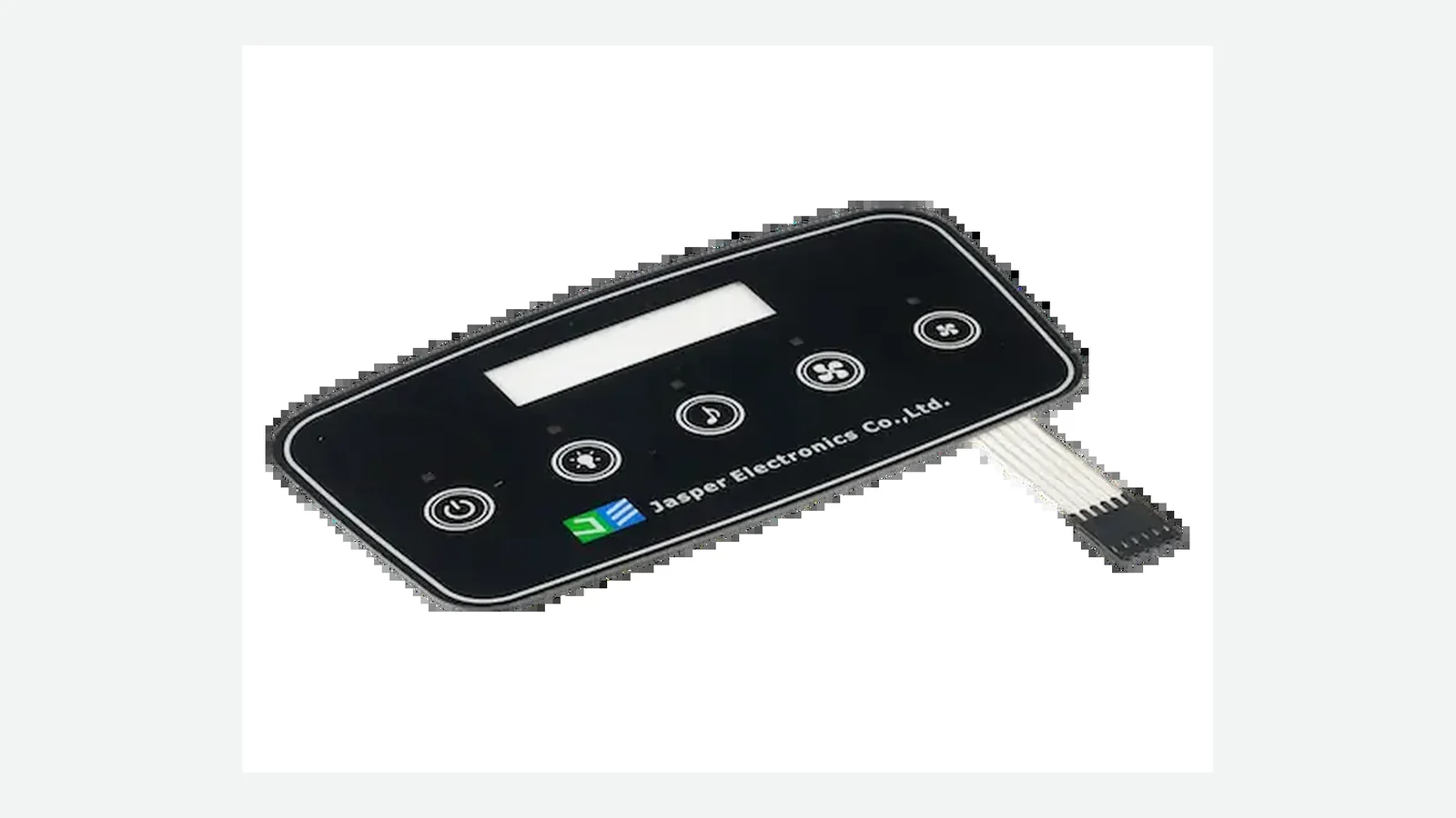
A membrane switch vs mechanical switch decision for an OEM control panel is an architecture choice, not a catalog preference. The question is which construction can carry the operator task, the enclosure sealing claim, the legend and lighting plan, the wiring path, and the service model without fighting the housing. This article is for mechanical, electronics, and industrial-design engineers who must freeze the interface approach before RFQ in 2026 programs. It compares membrane switches and discrete mechanical switches—class examples include industrial pushbuttons and PCB tactile series from catalogs such as Omron and C&K—on profile, feedback, sealing, graphics, serviceability, wiring, tooling, assembly, environment, and lifecycle framing. The decision rules apply to any qualified interface manufacturer.
Scope note: Consumer “mechanical vs membrane keyboard” articles from sites such as RTINGS answer typing feel for desktop keyboards. They do not decide industrial, medical, appliance, or equipment control panels. Those keyboard pages are out of scope here.
1. Quick verdict — at a glance
| Dimension | Membrane switch wins | Mechanical switch wins | Often a tie / hybrid |
|---|---|---|---|
| Overall profile / stack height | ✓ | ||
| Continuous wipe-clean face | ✓ | ||
| Custom multi-color legends & windows | ✓ | ||
| Enclosure sealing path (IEC 60529 framing) | ✓ | with discrete E-stop exceptions | |
| Dense multi-key layout, few cutouts | ✓ | ||
| Long travel / strong independent click | ✓ | ||
| Field replacement of a single key | ✓ | ||
| Direct higher electrical load switching | ✓ | ||
| Series-documented ultra-high cycle life per key | ✓ | method-dependent | |
| Mixed operator needs on one panel | ✓ hybrid |
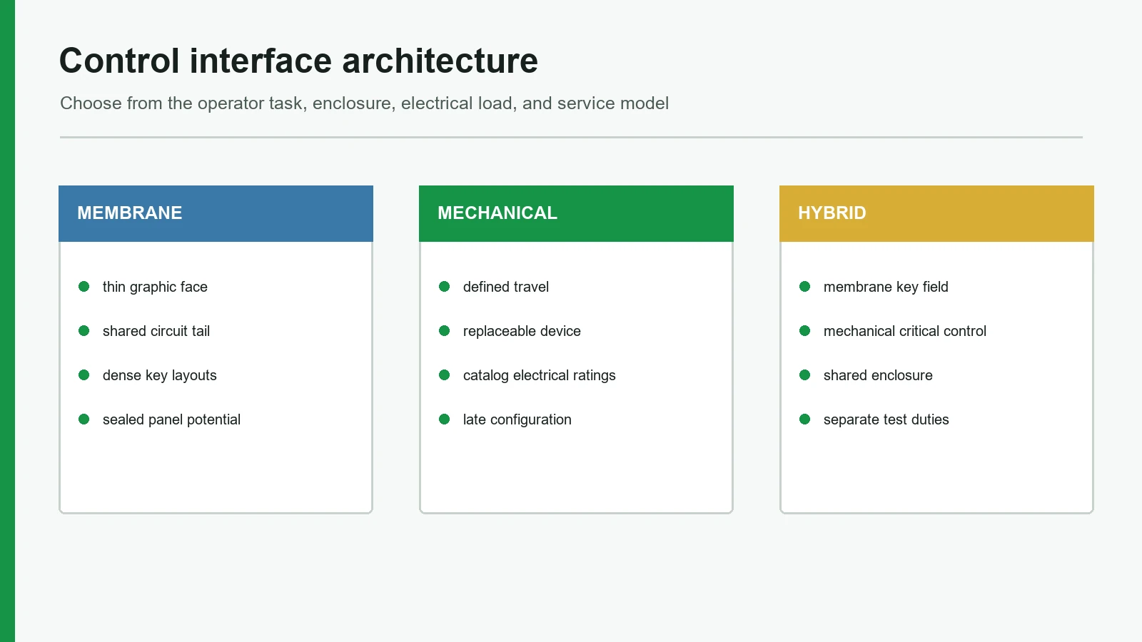
One-line summary: Choose membrane when the panel is a sealed graphic surface; choose discrete mechanical when individual actuators must travel, click hard, switch load, or swap in the field; choose hybrid when the panel needs both.
2. Membrane switch vs mechanical switch — side-by-side specs
The table below compares construction classes, not one universal part number. Membrane values describe a typical multi-layer flexible panel. Mechanical values describe discrete panel- or board-mounted switches (industrial pushbuttons, PCB tactiles, and similar). Exact numbers come from the selected series datasheet and the finished enclosure test plan.
| Spec / attribute | Membrane switch / membrane keypad panel | Discrete mechanical switch |
|---|---|---|
| Construction unit | Integrated multi-layer assembly under one graphic overlay | One switch mechanism per key (housing, actuator, spring/contact set) |
| Typical face | Continuous printed PET/PC (or similar) overlay | Individual keycaps or operators through panel holes |
| Profile | Low; industry-typical flexible stacks often land in a sub-mm to ~1–3 mm overall band depending on overlay, spacer, dome, and adhesive (verify on the project stack-up) | Higher; travel and housing set minimum height |
| Feedback | Flat non-tactile, emboss, poly dome, or metal dome (optional snap) | Inherent travel and snap/click from the mechanism |
| Sealing approach | Overlay + perimeter adhesive/gasket strategy; openings still control the claim | Each operator needs its own seal strategy or a sealed sub-assembly |
| Graphics | Full custom print, dead-front, windows, brand colors in one face | Legends usually molded, printed caps, or adjacent labels |
| Wiring | Shared flex tail / FPC / pin header to controller | Per-key terminals, harness, or PCB pads |
| Service model | Often whole-panel or subassembly swap | Single-key swap common when mounting allows |
| Electrical role | Usually low-level signal input to electronics | Signal or power/load switching per series rating |
| Tooling character | Print tools, dies, spacers, emboss, fixtures for the panel | Part selection + panel cutouts + harness/PCB layout |
| Primary failure modes | Overlay wear, adhesive lift, open/short in printed circuit, dome fatigue, tail/connector damage | Contact wear/oxidation, spring fatigue, actuator breakage, seal leak at each hole |
2.1 Construction stacks (text diagrams)
Membrane switch stack (typical flexible build — project layers differ):
Operator face
Graphic overlay (printed, optional hard coat / emboss / dead-front)
Overlay adhesive
Optional metal dome or poly dome + retainer / retainer
Upper circuit (if used)
Spacer with key openings (+ vent concept if tactile domes)
Lower circuit (silver, copper flex, or hybrid)
Rear adhesive / gasket features
Mounting surface or support plate
Flex tail → stiffener → board connector (ZIF/LIF/pin)
Discrete mechanical switch (class sketch):
Operator face
Keycap / actuator head
Switch housing through panel or on PCB
Spring / mechanism
Electrical contacts (rating per series)
Terminals or PCB pins
Panel cutout + optional local gasket / boot
Harness or board trace to controller / load
A membrane keypad vs mechanical buttons is therefore not only “soft vs clicky.” It is one laminated assembly with shared interconnect versus N independent mechanisms with N mounting and sealing interfaces.
2.2 Feedback is optional on membrane; inherent on mechanical
Discrete mechanical switches build travel and confirmation into the part. Membrane panels can be flat and quiet, embossed only, or fitted with metal domes for a snap. Metal domes are normally open momentary contacts. Trip force and release force define tactile ratio as (Fmax - Fmin) / Fmax x 100. Available actuation force spans a broad component range, so the selected dome must be evaluated in the production overlay, spacer, vent path, actuator, and support. Trapped air degrades feel when no controlled vent path exists.
2.3 Sealing is an enclosure problem, not a sticker on the switch
IEC 60529 classifies degrees of protection provided by enclosures for electrical equipment (IEC webstore publication 2452). A membrane overlay can simplify a continuous face and reduce hole count, but IP language—whether IP54, IP65, or IP67 in a product requirement—still belongs to the evaluated assembly: panel edges, display openings, tail exit, connector path, gasket compression, and test orientation. Discrete mechanical keys can be sealed with boots, O-rings, or sealed switch series, yet every additional cutout is another interface to design and validate. Neither technology “is IP67” as a free-floating component claim.
3. Where membrane switches win
3.1 Sealed graphic faces on industrial and wash-down equipment
When operators wipe chemicals, food residue, dust, or coolant across a panel, a continuous overlay is usually easier to clean than a forest of key gaps. Industrial control faces, laboratory instruments, and appliance panels from white goods to food equipment use membrane construction because the legend, windows, and key zones live on one PET or PC film face. For industrial panel context, see industrial control panel membrane switches. The membrane switch advantages limitations pair is clear here: strong cleanability and graphic density, but limited ability to field-replace one worn key without a panel strategy.
3.2 Low profile and dense multi-key layouts
Membrane stacks keep height low and let engineers pack multi-key maps—industry planning examples often show 12, 24, or 40+ functions—without drilling a hole per key. Display windows, surface-mount LED indicators, and brand colors sit in the same face. That density is why OEM teams at machine builders often pick a membrane keypad when the housing has almost no free depth—an industry-typical usable stack budget after the support plate is often under ~3 mm, confirm on the enclosure section—and the UI must look like one product, not a bolted grid of catalog buttons.
3.3 Custom legends, dead-front icons, and lighting integration
Printed overlays carry multi-language text, symbols, color coding, and dead-front icons that only appear when lit. Film choice is grade-specific: PET and PC membrane films are supplied in distinct finishes and functional grades; neither polymer acronym defines a complete material specification. Lighting still needs optical design—masks, LED placement, light guides—but the graphic layer is part of the switch assembly rather than a separate nameplate campaign. Mechanical arrays can look industrial and durable; they rarely match full-face graphic freedom without extra overlays or printed housings.
3.4 Shared wiring and assembly simplification
One flex tail (or a small set of interconnects) can bring dozens of keys to a controller. TE Connectivity FPC and similar ZIF/LIF connector families show why the tail is not a free sketch: pitch, contact mating side, accepted flex thickness, orientation, and actuator style are connector-controlled. Assembly becomes place-and-bond the panel rather than install and wire each switch. That helps products where key count is no longer sparse—industry RFQ practice often starts noticing harness labor above about 10 keys—because hole tolerance stack-ups and wiring time dominate more than the switch mechanism itself. The limitation: a circuit open under one key may still force panel-level rework depending on repair policy.
When membrane is the wrong default: If the product’s critical controls need long travel, glove-friendly deep actuation, or individual hot-swap in the field, forcing every function into a flat membrane face creates operator and service debt. Those controls should stay mechanical or move into a planned hybrid.
4. Where mechanical switches win
4.1 Travel, force, and blind-operation confirmation
Operators who never look at the panel—gloved line workers, dark equipment bays, high-noise floors—often need a long, unambiguous stroke. Discrete mechanical switches deliver travel and click as designed into the series datasheet. Metal-dome membrane can approximate a snap, but it remains a short-travel film stack; industry-typical metal-dome travel is usually well under 1 mm (series-dependent—verify on the dome drawing). If the requirement is “feel the mechanism move,” mechanical wins.
4.2 Field service and single-key spares
A failed pushbutton can often be replaced without reprinting an entire graphic assembly. That matters for long-life capital equipment with sparse key counts and global spare programs. Membrane panels can be modularized (replaceable subassemblies, legend cards, secondary overlays), but the default construction is still an integrated face. Serviceability is a lifecycle cost decision, not a one-line BOM comparison.
4.3 Electrical ratings beyond signal-level inputs
Printed silver or copper flex membrane circuits are usually intended as low-level inputs to electronics, not as direct power switches. Discrete mechanical series from industrial catalogs exist for higher voltage and current ratings—often documented in VAC/VDC and amperage classes—with published contact materials and electrical life curves. If a control must break a load without a relay or solid-state intermediate stage, start from a mechanical (or hybrid with a rated contactor) architecture rather than overloading a printed silver or copper flex path.
4.4 Catalog modularity and late UI changes
When the UI is still fluid and the team wants to move one function next month, discrete switches on a PCB or panel grid absorb change with less artwork tooling. Membrane graphics, spacer openings, and circuit artwork move together—print screens, outline dies, and emboss tools often shift as a set. Early architecture freezes should match how often the legend set will change. Rear bonding also differs: example adhesives such as 3M 467MP (200MP acrylic for metals and high-surface-energy plastics) and 3M 9495LE (300LSE for many low-surface-energy plastics and powder coats) only make sense after the real enclosure finish is named.
When all-mechanical is the wrong default: If the enclosure must present a continuous sealed face with dense custom graphics, wiping, and thin packaging, a full discrete array multiplies cutouts, seals, and harness points. That is the classic control panel switch comparison failure mode: great individual buttons, poor panel system.
5. Hybrid designs — often the real OEM answer
Equipment panels often should not force one technology across every control. Common patterns:
| Pattern | Typical use | Watch-outs |
|---|---|---|
| Membrane face + discrete E-stop / power | Industrial and machine safety-critical operators | Maintain separate mounting, sealing, and electrical rating reviews |
| Membrane keypad + silicone rubber keys | Soft-touch zones or higher travel islands | Bonding, hardness, and legend durability become multi-process |
| Membrane / graphic overlay + capacitive zones | Sealed modern faces with mixed press and touch | Glove, water, and EMI validation on the capacitive path |
| PCB mechanical tactiles under a graphic overlay | Short-travel keys with overlay branding | Support flatness, actuator alignment, and venting still apply |
Blended interfaces are appropriate when environment, feedback, electrical load, and service requirements do not align across every key. A complete HMI assembly review should list each control's technology, rating, and spare policy before RFQ, not after First Article Inspection.
When hybrid is wrong: If the organization cannot stock two spare strategies, write two test methods, or own the mechanical interface between overlay and discrete operators, hybrid becomes a documentation failure. Pick one technology or fund the systems work.
6. Decision matrix and RFQ architecture checklist
6.1 Choose-if matrix
| If your priority is… | Pick |
|---|---|
| Continuous wipe-clean face, custom graphics, low profile, dense keys | Membrane switch / membrane keypad panel |
| Strong travel/click, single-key field replace, higher electrical rating | Discrete mechanical switches |
| Sealed graphic face plus a few high-criticality operators | Hybrid (membrane + discrete) |
| Software-rich menus, multi-language screens, gesture input | Capacitive / touch HMI (not pure membrane-vs-mechanical) |
| Quiet flat keys with almost no acoustic snap | Non-tactile membrane (see tactile vs non-tactile) |
| Metal-dome snap on a sealed face | Tactile membrane with coordinated vent and support |
| “One technology for everything” without service plan | Neither — rewrite requirements |
6.2 Failure and service chain (control panel switch comparison)
| Event | Membrane-oriented panel | Mechanical-oriented panel |
|---|---|---|
| Single key worn / intermittent | Often panel or circuit subassembly action | Replace that switch if accessible |
| Contaminant attack | Overlay chemistry and adhesive edges matter | Each operator gap and boot matter |
| Connector / harness damage | Shared tail is a single critical path | Distributed terminals; more points, more isolation |
| Legend change | New overlay/print revision | Cap change or label change may suffice |
| Seal test fail | Perimeter, windows, tail exit, enclosure joints | Same enclosure rules + every cutout |
6.3 Architecture checklist before RFQ
Use this list to select the interface architecture before RFQ—not after tooling quotes lock the wrong construction.
- Operator profile: bare finger, glove type, force, viewing angle, noise, blind operation.
- Environment: fluids, dust, UV, cleaning chemistry, temperature, outdoor exposure.
- Sealing claim: enclosure test article and IEC 60529 intent—not a switch-only label.
- Key map: which keys need long travel, which need silent flat press, which are safety-critical.
- Graphics & lighting: languages, dead-front, windows, LED/light-guide ownership.
- Electrical: signal vs load, voltage/current, ESD path, controller interface.
- Interconnect: flex tail vs harness vs PCB; connector series and contact side.
- Service model: whole-panel swap vs single-key spares; field tools allowed.
- Lifecycle evidence: which series datasheets and which panel-level tests apply.
- Hybrid ownership: if mixed, who owns mechanical cutouts, gasket, and BOM spares.
For drawing-level detail after architecture is chosen, use the membrane switch design guide and send the package through drawing review.
7. Frequently asked questions
Is a membrane switch always better than a mechanical switch for OEM panels?
No. Membrane construction fits sealed graphic panels and dense low-profile UIs. Discrete mechanical switches fit long travel, hard confirmation, field replace, and higher electrical ratings. The better choice follows the operator, enclosure, and service model—not a universal ranking.
When should an OEM use a membrane keypad vs mechanical buttons?
Use a membrane keypad when a multi-key face must stay wipe-clean under one graphic overlay. Use mechanical buttons when each control needs independent travel, a catalog electrical rating, or single-key service. Mixed panels appear when only two or three keys need mechanical behavior and the rest can stay flat.
Can one control panel mix membrane and mechanical switches?
Yes. Hybrid layouts often place membrane keys for routine functions and discrete operators for emergency stop, power, or high-force commands. Plan sealing, cutouts, wiring, and spares for both technologies before RFQ.
Does a membrane switch automatically give IP65 or IP67?
No. IEC 60529 rates enclosures under defined test conditions. A membrane face can help by reducing openings, but edges, windows, tails, gaskets, and the finished housing still decide the result.
Are mechanical switches always longer-life than membrane switches?
Not as a blanket rule. Life is series- and test-method specific. Some discrete switches publish very high electrical or mechanical life figures; membrane panels with appropriate materials and domes also serve long programs. Compare datasheets and panel tests, not slogans.
Do metal domes make a membrane switch “mechanical”?
No. Metal domes add a snap inside a membrane stack. They remain short-travel film assemblies. Venting, support flatness, and overlay stiffness still control feel (Snaptron venting and force guidance).
Which option is cheaper for a 20-key industrial panel?
Neither is universally cheaper. Membrane often reduces per-key hardware and harness labor at volume; mechanical can win on sparse key counts with catalog parts and simple panels. Quote both architectures only after the sealing and service models are fixed—otherwise the low bid is the wrong construction.
What should be frozen before RFQ on this decision?
Freeze technology map per key, operator conditions, sealing intent, interconnect approach, and service strategy. Artwork colors can iterate later; architecture mistakes reprint tools and re-cut housings.
Technical References
- Source: IEC 60529 enclosure protection classification. Accessed 2026.
- Source: IEC 61000-4-2 electrostatic discharge immunity testing. Accessed 2026.
- Source: IEC 60068 environmental testing method series. Accessed 2026.
- Source: ASTM F1578 membrane switch contact closure cycling practice. Accessed 2026.
- Source: Snaptron metal dome force and venting guidance. Accessed 2026.
- Source: Omron industrial pushbutton product specifications. Accessed 2026.
- Source: C and K tactile switch product specifications. Accessed 2026.
- Source: 3M 467MP and 9495LE adhesive technical data. Accessed 2026.
- Source: Covestro Makrofol and Bayfol Film Selector Guide. Accessed 2026.
- Source: TE Connectivity FPC connector product drawings. Accessed 2026.
- Source: UL 969 marking and labeling systems scope. Accessed 2026.
- Source: ISO 9241-210 human-centred design for interactive systems. Accessed 2026.
- Source: IPC-D-325 documentation requirements for printed boards and assemblies. Accessed 2026.
- Source: RoHS Directive 2011/65/EU restricted substances scope. Accessed 2026.
- Source: REACH Regulation EC 1907/2006 chemical substance framework. Accessed 2026.
Choose the interface architecture before RFQ
Send the operator task, panel envelope, sealing target, key map, electrical load, graphics, service model, and validation priorities.