
Dead front glass panel printing succeeds only when OFF-state concealment, ON-state readability, display-window appearance, capacitive touch, assembly alignment, and inspection are specified together. This guide shows HMI engineers and sourcing teams how to define those six states, select a print route, register every optical zone, and approve the powered product—not merely a decorated sheet of glass.
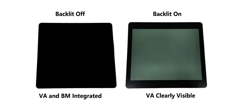
A dead-front panel is not just “black glass with hidden graphics.” It is an optical system whose appearance changes with the light source, ambient illumination, viewing geometry, display, touch stack, and housing. The decision covered here is how an OEM should prepare and approve dead front glass panel printing for a control interface. It does not select a universal ink, glass grade, transmission value, touch controller, or regulatory route. Those choices belong to the actual product requirements and verified supplier data.
1. A Dead-Front Panel Has Six Acceptance States
Dead-front construction hides inactive graphics or display boundaries and reveals selected information when the product is energized. Boyd describes the basic effect as alternate colors printed behind a bezel or overlay so indicators remain hidden until backlit. That definition is useful, but a production drawing needs more than an OFF/ON rendering.
Treat one panel as six separate acceptance objects:
| State | Question the state must answer | Typical evidence |
|---|---|---|
| OFF | Are inactive icons, windows, cavities, and components acceptably concealed under defined ambient conditions? | Controlled ambient-light inspection, reference sample, photographs, instrument data where applicable |
| ON | Are active dead front icons readable, uniform, correctly colored, and free from unacceptable halo or hotspots? | Powered light fixture or product assembly, luminance/contrast records, approved visual master |
| Display | Does the active image align with the mask, retain required readability, and blend with the border when inactive? | Powered display with controlled test images, viewing-angle checks, window measurements |
| Touch | Does the complete dielectric and electrical stack meet the product’s touch criteria? | Final cover, print, adhesive/air gap, sensor, controller, grounding, display-noise state, and test protocol |
| Assembly | Do glass, print, light, display, sensor, adhesive, and housing features share a controlled datum chain? | Dimensioned assembly drawing, tolerance analysis, first-article measurements |
| Inspection | Can production reproduce the acceptance decision with a defined fixture and record? | Work instruction, fixture drawing, calibrated equipment list, sampling and reaction plan |
The failure cost starts when teams approve only one state. An OFF-state sample may conceal the artwork beautifully yet transmit too little light when powered. A bright ON-state sample may leak inactive symbols under office lighting. A printed icon can meet its glass datum while missing the LED cavity after assembly. A bare sensor can respond on a bench and then lose margin behind the printed glass, adhesive, display, ground plane, and wet surface.
A useful design review therefore asks six questions, not one. The commercial page for glass nameplates can define available cosmetic and construction options, while the project specification must define what the installed HMI accepts in each state.
2. Map the Complete Optical and Electrical Stack
The print artwork sits inside a physical stack. Every interface can change the result seen by a user or detected by a capacitive controller.
Viewer / ambient light
Front-surface texture or optical coating
Glass substrate and strengthening history
Rear-surface border, mask, color, and translucent print layers
Adhesive, optical adhesive, perimeter bond, or controlled air gap
Capacitive sensor and its electrode / routing pattern
Display, LED, light guide, diffuser, reflector, and cavity walls
Grounding, controller, electronics, and enclosure
Housing datums and final product geometry
Glass control panel printing changes reflection, absorption, and transmission before light reaches the viewer. Adhesive or an air gap adds another optical interface. The touch sensor and display may introduce visible patterns or electrical noise. Cavity walls can create a halo; a diffuser can reduce a hotspot but spread light into an adjacent symbol. Surface treatments can alter glare and apparent black matching. None of those effects is represented by the print file alone.
Texas Instruments’ CapTIvate design guidance treats the overlay, electrodes, spacing, grounding, moisture, environment, and controller settings as parts of one capacitive system. That is why a printed cover intended for capacitive touch panels should be evaluated with the actual sensor and controller architecture. Passing a cosmetic glass inspection does not prove touch performance, just as a responsive bare sensor does not approve the decorated cover.
Ownership must follow the interfaces. Industrial design owns the intended visual hierarchy. Optical engineering owns source, spectrum, window, and viewing conditions. Mechanical engineering owns datum transfer and stack dimensions. Electrical or firmware teams own touch tuning and illumination drive. Quality engineering turns those requirements into repeatable fixtures and records. The glass processor can advise on printability, but cannot infer all product-level limits from artwork.
3. How to Specify Dead-Front Glass Panel Printing
A release package should pass ten checks. Each criterion below includes a acceptance evidence and a release blocker that an engineering or sourcing team can use during supplier review.
3.1 Define Every Operating State Before Choosing the Ink
Start with OFF, ON, display, touch, assembly, and inspection requirements. Record the environment and product configuration for each state before comparing material routes. This order matters because an ink that looks correct over a bright LED in a dark room may not meet concealment under 1,000-lux office lighting, and a dark stack that masks a display border may reduce powered readability.
The requirement set identifies the source, product state, ambient illuminance, viewing geometry, image content, background, specimen configuration, and pass/fail owner for each applicable state.
The specification says “icons invisible when off and bright when on” without defining invisible, the ambient condition, the powered stack, or who accepts a borderline result.
3.2 Build an Optical-Zone Register, Not Just Artwork Layers
Artwork files describe geometry and color separations. An optical-zone register describes function and acceptance. Assign a stable zone ID to every border, hidden icon, status aperture, display window, touch key, logo, keep-out area, and coating boundary. Link each zone to a datum, print layer, backing component, measurement method, target, tolerance, owner, and change trigger.
A zone can participate in more than one state. A display window has an OFF-state border-match requirement, an ON-state image requirement, an assembly mask-overlap requirement, and perhaps a touch requirement. A status icon has a concealment requirement when inactive and an illumination requirement when active. Separating those rows exposes conflicts while they are still inexpensive to resolve.
The same zone IDs appear in the artwork, mechanical drawing, optical register, light/display drawing, inspection plan, and first-article report.
The supplier receives PDF artwork with color callouts but no relationship to the LED, display active area, sensor electrode, adhesive opening, or housing datum.
3.3 Choose a Material and Process Route as a Controlled System
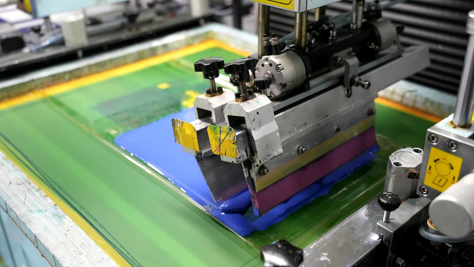
“Glass ink” is not one process. an inorganic glass-enamel route that is printed and fired so the enamel matures and bonds to glass. an organic solvent-based screen ink suitable for substrates that include glass. These families differ in chemistry, thermal history, processing window, rework behavior, appearance, and compatibility constraints.
The route must be reviewed against glass composition, strengthening, coatings, edge and hole processing, print side, layer order, adhesive, optical target, expected exposure, and the sequence in which those operations occur. A supplier technical data sheet supports the named material under its stated conditions; it does not validate an altered stack or another supplier’s process.
One practical test: ask what happens if printing moves earlier or later in the routing. Cutting, drilling, edge finishing, chemical strengthening, heat treatment, coating, printing, cure or firing, bonding, and final assembly do not commute freely. Stop. If a proposed sequence contradicts the current glass, ink, enamel, coating, or adhesive supplier instructions, the project needs documented engineering resolution before samples are treated as representative.
The controlled bill of materials names the material family and exact approved product, while the process flow identifies preparation, layer order, intermediate steps, cure or firing, inspection, and prohibited substitutions.
A drawing calls out “black glass ink” and “transparent black” with no supplier grade, process route, layer order, compatibility review, or change-notification rule.
3.4 Specify OFF-State Concealment as a Viewing Condition
Absolute black and absolute invisibility are not practical drawing terms. A user sees reflected ambient light, glass surface reflection, printed-layer differences, backing components, display polarizers, gaps, and local geometry. The same panel can hide an icon at normal incidence and reveal it at an oblique angle or under a point source.
Define the OFF-state fixture: ambient illuminance and source type, panel orientation, observer distance and angle, background, display power state, LED state, and whether the specimen is loose glass or a complete assembly. For instrumental color work, ASTM E1164-23 covers spectrometer parameters, calibration, standards, and specimen selection. ASTM E308 provides a route from spectral data to CIE color coordinates. Those methods improve repeatability, but the buyer still has to define an acceptable visual or numerical difference.
A signed reference assembly and an instrument method are linked to the same viewing condition, with permitted border-to-zone difference and leakage class stated on the control plan.
Approval depends on holding a loose panel near a window and deciding whether it “looks black enough.”
3.5 Treat ON-State Transmission as a System Variable
A transmission percentage is incomplete without spectral range, measurement geometry, aperture, specimen stack, and tolerance. It is also not a direct substitute for icon luminance, contrast, color, or uniformity. The source spectrum, LED drive, cavity depth, reflector, diffuser, mask overlap, ink spectrum, glass, ambient light, and observer angle all influence the powered result.
Use 10% as an initial sample target only when the optical-zone register calls for a low-transmission dead-front icon. Approve the transmission band, spectral range, specimen, viewing geometry, and tolerance on the finished glass stack before release.
3.6 Give Display Windows Their Own Optical Contract
A display window is not simply a clear hole in black print. It may require an inactive border match, an active image contrast target, controlled mask overlap, a defined active-area relationship, acceptable reflection, color neutrality, viewing-angle performance, and a bonding or air-gap condition. The display’s polarizer and inactive black level can remain visible through an otherwise well-matched printed border.
Release at least three image states: full black, full white or a high-output service screen, and a registration pattern that marks the active-area boundary and centerlines. If the final product uses optical adhesive, perimeter bonding, or a designed air gap, approve the window in that condition. A loose-glass reading cannot represent all interface reflections or stress introduced by the assembly.
The display supplier drawing, cover-glass mask, adhesive opening, and housing aperture reference the same product datums, with overlap and viewing-angle requirements documented.
The window is accepted over a printed paper image or an unpowered display with no active-area registration pattern.
3.7 Validate Capacitive Touch Through the Final Stack
Printed layers alter the dielectric stack and can change the distance, coupling, and noise environment seen by a capacitive sensor. Adhesive thickness variation or a local air gap may matter. A display, charger, motor, wet surface, gloved hand, enclosure ground, and neighboring electrodes can change signal conditions. mechanical design, electrode geometry, environmental effects, grounding, and controller configuration interact.
Validation should use the final or worst-case glass thickness, approved print stack, adhesive or gap, sensor revision, controller and firmware, grounding, display state, illumination state, enclosure, and intended use conditions. The related capacitive touch control panel route provides application context, but it is not evidence that this specific stack passes a touch requirement.
The design-verification plan identifies touch targets, false-activation limits, environmental states, noise sources, sample corners, controller settings, and retest triggers.
A supplier or project team treats glass printing as cosmetic and approves touch using a bare sensor on an open bench.
3.8 Extend Registration From Print Layers to the Installed Product
Print-to-print registration aligns border, color, mask, and translucent layers. Print-to-glass registration locates those layers relative to glass edges, holes, or fiducials. Glass panel optical registration goes farther: it locates the visible result relative to the LED cavity, light guide, display active area, touch electrode, adhesive opening, and housing aperture.
Define one functional datum reference frame. A cosmetic outer edge may be a poor primary datum if the panel locates in the housing through holes or machined features. Allocate the permitted misalignment across glass fabrication, print placement, display/light placement, sensor lamination, adhesive conversion, and final assembly. Statistical assumptions must match the manufacturing plan; simply adding every bilateral tolerance may be overly conservative, while root-sum-square treatment may be unsafe without capable and centered processes.
A tolerance analysis traces each optical zone from product datums through every component and assembly operation, then verifies the result on first articles.
The print shop reports excellent layer registration, but no drawing controls the distance from the printed icon to the assembled LED or display pixel area.
3.9 Make the Inspection Fixture Part of the Requirement
If fixture geometry changes the answer, the fixture belongs in the specification. OFF-state inspection needs controlled ambient light and observation geometry. ON-state inspection needs a repeatable source, drive condition, cavity, diffuser, and panel position. Display checks need controlled content. Touch checks need the final electrical stack. Assembly checks need defined datums and measurement access.
The inspection sequence should begin with OFF-state leakage before energizing the product; visual adaptation and residual impressions can bias a later OFF judgment. Then inspect active icons one at a time and in relevant combinations, followed by display images, touch states, and dimensional evidence. The quality and testing framework can organize requirement, specimen, method, result, acceptance, and record, but it does not represent a test pass for this project.
Fixture revision, instrument identification, calibration status, software/image revision, sample conditioning, photographs, raw readings, and disposition are retained with the first-article record.
Production operators compare panels under uncontrolled ceiling lights using an unapproved LED board and no recorded viewing distance.
3.10 Tie Change Control to the States and Interfaces Affected
A change can be cosmetic, optical, electrical, mechanical, or several at once. Ink-lot or supplier changes may affect color and transmission. A glass-thickness change can affect touch and fit. A display or polarizer revision can affect inactive black matching. A diffuser, LED bin, cavity finish, adhesive thickness, coating, strengthening route, firmware setting, or housing datum change can invalidate prior evidence.
Create a change-trigger matrix that maps each controlled item to OFF, ON, display, touch, assembly, and inspection revalidation. Not every change needs every test, but the exclusion should be justified. Supplier notification must cover raw materials, process route, equipment or tooling, site, sub-tier source, inspection method, and specification revision where relevant.
The approved-part record contains a state-specific requalification plan and defines who may accept a reduced test scope.
A new ink or display is released after a flat color comparison because dimensions and artwork revision did not change.
A state-based change matrix keeps the retest decision consistent:
| Changed item | OFF | ON | Display | Touch | Assembly |
|---|---|---|---|---|---|
| Border or translucent print material | Retest | Retest | Review | Review | Verify dimensions |
| LED, diffuser, or cavity finish | Review | Retest | If shared light path | If noise/heat changes | Verify location |
| Display or polarizer | Retest | If indicator interaction | Retest | Retest noise state | Verify active-area location |
| Glass, adhesive, sensor, or controller | Review | Review | Review interfaces | Retest | Retest fit and datums |
“Review” means an authorized engineer documents why prior evidence remains applicable; it does not mean the state is silently omitted.
4. Choose the Construction Route by the Required State
No construction wins every project. The correct route is the one that meets the six-state requirements while remaining compatible with the glass and process sequence.
| Route | Where it can fit | Main engineering questions | Evidence required before release |
|---|---|---|---|
| Inorganic fired enamel | Projects whose glass and thermal sequence support a fired decorative layer | Is the enamel compatible with the glass, strengthening route, coatings, print side, firing profile, and later bonding? | Named supplier TDS, approved process flow, fired samples, optical and adhesion evidence under project conditions |
| Organic screen ink | Multi-layer graphics or lower-temperature processing where a qualified organic system meets use conditions | Are substrate preparation, catalyst/mix if applicable, layer order, cure, adhesion, optical density, and exposure compatible? | Exact ink-system data, controlled cure, stack samples, optical/color/adhesion and application-specific validation |
| Tinted glass, coating, or film-assisted route | Larger optical areas or designs where the substrate/interface helps create the inactive appearance | How do reflection, transmission, color, bonding, touch, durability, and supplier variability interact? | Optical spectra, interface/adhesion data, final display and touch assemblies, environmental and change-control evidence |
| Alternative polymer overlay or separate bezel | Lower mass, impact-flexible, highly contoured, replaceable, or cost-sensitive interfaces where rigid glass is unnecessary | Can the alternative meet scratch, chemical, optical, tactile, sealing, and appearance requirements? | Material-specific validation and a product-level comparison against glass |
Vibrantz and Nazdar demonstrate why “ink type” cannot be separated from process. Their technical documents apply to named product families and conditions. The buyer should request the current technical and safety data, then ask the processor to identify deviations, sub-tier operations, and the exact point at which strengthening, coating, printing, curing/firing, and bonding occur.
5. Create an Optical-Zone Register Before Releasing Artwork
The register below is a template, not a finished specification. It makes hidden assumptions visible and gives engineering, suppliers, and quality teams one shared record.
| Zone ID | Function | OFF requirement | ON / active requirement | Primary datum | Measurement / fixture | Limit and status | Change trigger |
|---|---|---|---|---|---|---|---|
| B01 | Opaque border | No unacceptable component or cavity show-through under defined ambient setup | Not applicable; prevent stray-light leakage | Product A-B-C | OFF fixture + color method | Project-defined; open | Ink, glass, coating, backing, cavity finish |
| I01 | Hidden status icon | Match approved inactive reference at specified angle/distance | Required symbol readable without unacceptable hotspot, halo, or adjacent activation | Product A-B-C | OFF fixture; powered icon fixture | 10% transmission example: initial project-specific only; replace method/tolerance | Ink stack, LED/bin/drive, diffuser, cavity, glass |
| W01 | Display window | Border and inactive display blend within approved condition | Active image meets project contrast, color, and viewing-angle criteria | Display centerlines to A-B-C | Powered display with black/white/registration images | Project-defined; open | Display/polarizer, adhesive/gap, mask, coating |
| T01 | Capacitive key | Same visual requirements as its local surface zone | Meets touch protocol through final stack | Electrode center to A-B-C | Final product touch fixture | Project-defined; open | Glass/print/adhesive, sensor, controller, firmware, ground |
| A01 | Indicator aperture | No unwanted cavity outline or adjacent icon leakage | Luminous area lies inside graphic aperture throughout tolerance stack | Light cavity to A-B-C | Powered assembly + dimensional check | Project-defined; open | LED/light guide, print, assembly tooling |
| K01 | Optical keep-out | No print, adhesive edge, electrode trace, or housing feature enters protected area | Preserve display/light/touch optical path | A-B-C | Drawing and vision inspection | Dimensioned boundary; open | Artwork, die-cut, sensor, housing revision |
The initial 10% value illustrates the shape of a requirement, not its completeness. Before release, replace it with a statement such as: wavelength or photopic range; instrument; aperture; illumination/collection geometry; specimen stack; conditioning; nominal; tolerance; sampling; and relationship to powered luminance or contrast. ASTM C1649-25 can inform instrumental transmittance measurement for flat glass, but it does not decide the HMI target.
For color, ASTM E1164-23 and ASTM E308 can establish acquisition and calculation discipline. ASTM D2244 defines color-difference calculations. Purchaser and seller must agree on the permissible tolerance and procedure. A lone “ΔE” value without color space, illuminant, observer, geometry, backing, surface, and visual correlation remains ambiguous.
6. Control Product-Level Optical Registration
A complete datum chain prevents a locally correct print from becoming a visibly wrong product.
Housing locating features
glass locating features
printed border / icon / window
adhesive opening
touch electrode
LED cavity or display active area
Use functional datums that represent how the product locates. Record coordinate origin, axis direction, units, drawing scale, glass-view side, print-view side, mirroring convention, and layer naming. Put fiducials outside critical viewing zones when possible, but ensure the assembly and inspection processes can use them. A camera system that registers one print layer does not automatically verify the LED, display, or sensor after downstream assembly.
The failure chain is straightforward:
Datum ambiguity → layer or component shift → reduced mask overlap → light leakage, halo, clipped symbol, visible display edge, or touch-zone offset → inconsistent first-article decision → production rejection or an ambiguous user indication.
| Registration level | What it aligns | What it does not prove |
|---|---|---|
| Print-to-print | Border, mask, color, and translucent layers | Location on the glass or in the product |
| Print-to-glass | Printed geometry to glass edges, holes, or fiducials | LED, display, sensor, adhesive, or housing position |
| Component-to-component | Display, light, sensor, adhesive, and housing features | Visual acceptance under powered conditions |
| Product optical | The visible OFF/ON/display result in the assembled datum chain | Long-term performance outside the validated conditions |
Tolerance allocation should begin at the visible failure boundary. For an icon, determine how far the luminous area can move before it clips or lights an adjacent feature. Divide that allowance among print placement, glass fabrication, LED/light-guide location, adhesive conversion, and assembly. For a display, start with required mask overlap around the active area and include viewing-angle/parallax effects where relevant. For a touch key, relate graphic center, electrode geometry, and finger target while leaving tuning margin to the electrical team.
Do not publish a universal registration tolerance. Feature size, glass size, process, datum scheme, mask overlap, viewing distance, and risk differ too much. A supplier should instead show process capability against the project drawing and identify which contributors occur outside its control.
7. Run a Six-Step Approval Process
Step 1 — Freeze the Product Coordinate System
Release a master mechanical drawing before color separations. Define product datums, glass orientation, front/rear view, printed side, origin, axes, units, critical-to-function dimensions, display active area, light cavities, touch electrodes, adhesive openings, and housing apertures. Resolve mirrored artwork conventions in writing. The goal is one coordinate language across industrial design, glass, electronics, and assembly.
Step 2 — Issue the Optical-Zone Register With the Artwork
Send vector artwork, layer names, color references, zone IDs, and the register together. For each zone, state OFF and active behavior, viewing or measurement conditions, ownership, and unresolved items. Include the initial values only when clearly flagged. Ask the processor to return a print-stack proposal, current material data, process sequence, manufacturability comments, and every requested deviation.
Step 3 — Review Materials and the Process Sequence
Compare fired enamel, organic ink, and any coating, tinted-glass, or film-assisted route against glass processing and final interfaces. Confirm whether cutting, drilling, edge work, strengthening, coating, printing, curing/firing, inspection, bonding, and assembly occur in a compatible order. Record sub-tier operations and prohibited substitutions. A current supplier data sheet is necessary but not sufficient; the released stack still needs product-level evidence.
Step 4 — Approve State Coupons, Then a Full Panel
Early coupons can isolate color, transmission, opacity, layer interaction, and process feasibility. They save time, but they do not prove full-area uniformity, datum transfer, display matching, touch behavior, or installed lighting. Move from material coupons to a full-size decorated panel, then to a powered assembly. Keep rejected samples and reasons in the development record so later revisions do not repeat failed combinations.
Step 5 — Inspect First Articles in the Six-State Sequence
Inspect OFF leakage first under the controlled fixture. Energize each icon and relevant combination; check uniformity, halo, adjacent leakage, color, and readability. Run the display’s black, white/high-output, and registration images. Test touch in the released stack and product states. Measure critical assembly coordinates from the product datums. The first-article report should identify every sample, fixture, instrument, software revision, and result.
Step 6 — Release a Golden Assembly and Change Matrix
A loose glass master cannot capture every product-level interaction. Retain an approved powered assembly or a controlled equivalent with its drive settings, display content, controller/firmware, ambient setup, and inspection instructions. Link it to the zone register, drawing revision, bill of materials, and change-trigger matrix. Define storage life and replacement rules for visual masters so aging does not silently change the reference.
8. Use a Six-State Validation Matrix
The validation matrix converts appearance language into controlled evidence. Tailor the methods and limits to the product; do not copy the examples as universal requirements.
| State | Minimum controlled inputs | Example outputs | Decision owner |
|---|---|---|---|
| OFF | Ambient source/illuminance, angle, distance, background, display/LED power, assembled stack | Leakage class, border-zone color difference, visible component/cavity record | Industrial design + optical + quality |
| ON | LED or light source, bin/spectrum, drive, cavity, diffuser, icon combination, ambient state | Luminance/contrast, uniformity, color, halo/hotspot, adjacent leakage | Optical + electrical + industrial design |
| Display | Display/polarizer revision, black/white/registration images, drive, adhesive/gap, viewing angles | Mask overlap, inactive blend, active readability, reflection/color record | Display/optical + mechanical |
| Touch | Glass/print/adhesive stack, sensor, controller/firmware, ground, enclosure, display/noise, wet/glove conditions | Detection margin, false activation, multi-key behavior, recovery | Electrical/firmware + system validation |
| Assembly | Product datums, component revisions, tooling, adhesive conversion, housing | Coordinate results, overlap, gap/flushness, zone-to-component offsets | Mechanical + supplier quality |
| Inspection | Fixture revision, instruments, calibration, conditioning, sequence, sampling | Repeatability/reproducibility evidence, traceable records, reaction plan | Quality |
A graphic overlay printing capability may help prepare separations, color targets, opacity layers, and inspection artwork. For rigid glass, the same artwork discipline must be extended through the complete optical and electrical stack. That extension is the difference between a decorated component release and a controlled HMI release.
The standards and source roles should also remain explicit:
| Entity | Appropriate use in this guide | Not established by the source |
|---|---|---|
| ASTM E1164-23 | Spectrometer parameters, calibration, standards, and specimen discipline | A JASPER color tolerance or visual acceptance limit |
| ASTM E308 | CIE color-coordinate calculation from spectral data | Specimen geometry or permissible color difference |
| ASTM D2244 | Color-difference calculation and buyer/seller agreement principle | A universal ΔE pass/fail value |
| ASTM C1649-25 | Instrumental transmittance framework for flat glass | A universal dead-front transmission target |
| Texas Instruments CapTIvate | Whole-stack capacitive-design dependencies | Approval of a JASPER controller, sensor, or firmware |
| Vibrantz Technologies / Nazdar | Evidence that fired enamel and organic ink are distinct process families | Proof that JASPER uses either named product |
9. When Dead-Front Glass Is Not the Best Choice
Dead-front glass is the wrong construction when its benefits do not justify its optical, mechanical, or validation burden. Consider another interface when:
- the product needs a flexible or strongly contoured surface;
- impact behavior, mass, service replacement, or cost favors a polymer overlay or separate bezel;
- the light budget cannot tolerate the opacity needed for OFF-state concealment;
- a display must remain readable across extreme ambient and viewing conditions that the proposed dark stack cannot support;
- touch margin is inadequate through the required glass and print stack;
- frequent graphic changes make permanent glass decoration impractical;
- the project cannot control LED, display, adhesive, sensor, and housing revisions tightly enough to preserve the approved appearance.
A conventional visible icon, lighter window, physical indicator, separate light pipe, polymer overlay, or unprinted display cover may produce a safer and more maintainable result. The correct decision follows the product states, not a styling trend.
10. Project Input Checklist: Review the Artwork and Optical Zones
Before requesting a process proposal or first article, assemble this package:
- dimensioned glass and assembly drawings with functional A-B-C datums;
- vector artwork with view/mirroring convention and stable layer names;
- optical-zone register covering border, icons, display, touch, apertures, and keep-outs;
- glass, strengthening, surface-treatment, and print-side requirements;
- LED/light-guide/diffuser or display data, drive conditions, and active-area drawing;
- touch sensor, controller, grounding, adhesive/gap, enclosure, and use-state information;
- OFF, ON, display, touch, assembly, and inspection acceptance conditions;
- approved measurement methods, initial items, and decision owners;
- material/process change-notification and revalidation matrix.
JASPER can be considered as one route to review the glass artwork and optical zones against a proposed panel stack. The review should begin with unresolved interfaces and evidence needs, not with a claim that one ink or transmission value fits every product.
Frequently Asked Questions
What is dead front glass panel printing?
Dead front glass panel printing creates selected graphics or windows that remain subdued when unlit and become readable when illuminated. The effect comes from the complete glass, print, light/display, adhesive, sensor, and housing stack; it is not a property of black ink alone.
How are dead front icons hidden when the backlight is off?
Dead front icons are concealed by controlling reflection, absorption, transmission, border matching, backing components, and viewing conditions. A translucent optical zone must pass enough intended light when active while avoiding unacceptable contrast against the surrounding border when inactive.
Is there a standard transmission percentage for dead-front glass?
No universal transmission percentage applies to every dead-front HMI. Abrisa publishes 5% and 10% options for its own offering, but the project value must reflect source spectrum, drive, diffuser, cavity, ambient light, viewing geometry, specimen stack, and required powered contrast.
What is the difference between print registration and glass panel optical registration?
Print registration aligns the individual ink or enamel layers. Glass panel optical registration also aligns the printed zones to glass features, LEDs or light guides, display active area, touch electrodes, adhesive openings, and housing apertures in the assembled product.
Should a dead-front panel use fired enamel or organic ink?
Neither route is universally best. Fired enamel can suit compatible glass and thermal sequences; organic ink can suit other graphics and processing needs. The decision must use the exact glass, material data, layer order, cure or firing route, optical targets, bonding stack, exposure, and validation plan.
How should OFF-state appearance be inspected?
Inspect OFF-state appearance before energizing the panel, using a fixed ambient source and illuminance, panel orientation, viewing angle and distance, background, and assembled backing condition. Record both the visual decision and any specified instrumental color or transmission data.
Can capacitive touch be approved before the final printed glass is available?
Early sensor testing can guide development, but it cannot approve the final interface. Release testing needs the specified glass, print layers, adhesive or air gap, sensor, controller and firmware, grounding, display/noise state, enclosure, and intended wet or glove conditions.
What should be included in a dead-front glass first-article report?
The report should identify samples, drawing and artwork revisions, materials, process route, fixtures, instruments, calibration, drive settings, display images, touch configuration, OFF/ON/display results, product-level registration measurements, deviations, photographs, disposition, and required revalidation triggers.
Technical References
- Source: ASTM E1164-23 object-color spectrometry. Accessed 2026.
- Source: ASTM D2244-16 color-difference calculations. Accessed 2026.
- Source: ASTM C1649-25 flat-glass transmittance. Accessed 2026.
- Source: ASTM E308-18 CIE color computation. Accessed 2026.
- Source: ASTM C1048-18 heat-strengthened and tempered glass. Accessed 2026.
- Source: IEC 60529:1989+A2:2013 enclosure ingress protection. Accessed 2026.
- Source: ISO 9241-303:2011 electronic visual display requirements. Accessed 2026.
- Source: Texas Instruments CapTIvate Technology Guide. Accessed 2026.
- Source: Vibrantz Automotive Glass Enamels technical data, 2023. Accessed 2026.
- Source: Nazdar 59000 Series Enamel Plus technical data. Accessed 2026.
- Source: Abrisa Technologies dead-front panel technical guide. Accessed 2026.
- Source: Boyd dead-front printing technical guide, 2022. Accessed 2026.
- Source: CIE 15:2018 Colorimetry. Accessed 2026.
- Source: ISO 2409:2020 cross-cut adhesion testing. Accessed 2026.
- Source: ASTM D3359-23 coating adhesion by tape test. Accessed 2026.
- Source: ASTM D1003-21 haze and luminous transmittance. Accessed 2026.
- Source: ASTM E1164-23. Accessed 2026.
- Source: ASTM E308. Accessed 2026.
- Source: ASTM C1649-25. Accessed 2026.
- Source: ASTM D2244. Accessed 2026.
Review the finished overlay construction before release
Send the drawing, artwork, substrate, adhesive, assembly, environment, optical states, and acceptance evidence for a construction-specific review.