
Bus seat occupancy sensor design should begin with the state a fleet needs from each named seat, then work backward through the cushion, sensing zone, interconnect, controller, and maintenance process. This guide helps seat engineers, vehicle integrators, sourcing teams, and fleet maintainers decide whether a flexible mat fits, which failure conditions to control, and what evidence to approve. The boundary matters: a seat sensor can report a seat state, but it does not by itself count boardings, alightings, trips, or passenger miles.
JASPER certifications: ISO 9001, ISO 13485, IATF 16949, and ISO 14001.
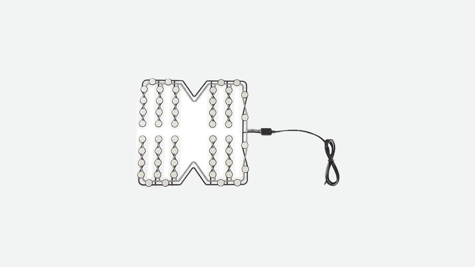
JASPER manufactures custom HMI components and flexible seat-sensing elements. JASPER's bus seat occupancy sensor route is one component option when the seat needs a shaped contact- or pressure-responsive mat. Where the project instead needs occupant classification, structural weighing, a driver display, telematics, or regulatory system ownership, another architecture or a complete system integrator may be the better choice.
Why Fleet Service Changes the Seat-Sensor Problem
A successful bench sample answers only one question: did that sample change electrically under that test load? Fleet release needs a longer answer. The production-intent seat must transfer passenger load into the intended zone while rejecting approved nuisance cases; the lead must survive its real route; cleaners must not create an unplanned conductive or mechanical path; and a technician must be able to disconnect or replace a seat without creating an unexplained state elsewhere.
The common failure chain is not confined to the sensing film. A seam can bridge the active zone, foam can settle, a cable can rub a frame edge, a connector can be swapped between adjacent seats, or a replacement cushion can shift the load path. None of those conditions is described by a loose-sensor cycle claim. There is therefore no defensible universal threshold, cycle life, debounce time, or IP rating for every fleet seat pressure mat.
Fleet records also change the evidence model. The FTA's guide to monitoring operations and maintenance procedures lists inspections, operational tests, audits, reviews, and data analysis as ways agencies can evaluate procedure compliance and sufficiency. A seat program can use the same evidence types without claiming that the FTA guide prescribes a sensor or a maintenance interval.
The design target is consequently a serviceable seat node: a stable seat ID, a controlled passenger zone, a known sensor revision, a traceable harness branch, a defined set of valid and invalid states, and an approved recovery action.
Choose the Observation Architecture Before Drawing the Mat
The best architecture is the simplest one that can make the required decision under the released seat conditions. “Detect a closed contact,” “estimate relative load,” “distinguish a person from baggage,” and “count people entering a bus” are different observations. Do not merge them. A combined requirement produces ambiguous thresholds and impossible supplier promises.
| Required observation | Candidate architecture | Useful when | Main limits to validate | Do not choose it when |
|---|---|---|---|---|
| Binary contact or occupied zone | Flexible switch/contact mat | The cushion load path is repeatable and the controller needs a simple state | Local preload, edge loading, open/short diagnostics, installation shift | Person-versus-object classification is mandatory |
| Relative load or several pressure zones | Analog resistive/FSR mat or pressure array | Distribution or multiple zones add useful evidence | Hysteresis, drift, temperature, foam aging, calibration ownership | The seat structure cannot reproduce the load path |
| Human proximity or occupant-type features | Capacitive or e-textile array | Dielectric response or classification features are needed | Wet trim, heaters, grounding, electromagnetic environment, occupant diversity | Only a passive dry-contact interface is available |
| Total load through the support structure | Load cell or strain-based structure | The seat frame offers a controlled force path | Structural variation, mounting, calibration, crash/load requirements | The frame or seat mounting changes across variants |
| Boarding, alighting, standing passengers, or cabin occupancy | Door counter, optical, radar, or combined system | The required output concerns people flow or the complete cabin | Occlusion, privacy, compute, power, network, validation method | The procurement scope is only a flexible seat component |
Public research illustrates the boundary, not a universal winner. The 2020 Bus Seating Information Technology study combined force-sensitive seat inputs with door infrared sensors, GPS, a camera, and cloud reporting in a 20-seat prototype. A 2014 University of Pretoria project tested a single-electrode capacitive approach in a minibus-taxi context. The Hong Kong Transport Department separately listed pressure-sensitive and infrared occupancy options in a green-minibus proof-of-concept plan. Each source reports a bounded architecture or planned comparison; none qualifies a generic bus product.
When a Flexible Pressure Mat Is Not the Best Choice
A flexible mat is a poor fit when the actual requirement is FTA-approved APC data for NTD reporting, reliable person-versus-baggage classification, structural weight measurement, or a complete safety/warning system with an ECU, display, diagnostics, and vehicle approval. It is also the wrong choice when the cushion stack cannot deliver repeatable load, the tail cannot leave the seat without abrasion or sharp bending, or service access requires pulling on the sensing element. Stop there. Reopen the system architecture.
The 10-Point Bus Seat Occupancy Sensor Design Framework
A release-ready design controls ten linked decisions: observation, architecture, passenger zone, seat stack, interconnect, cleaning exposure, nuisance states, service variants, validation, and production change. A strong supplier response makes each decision testable. A weak response substitutes a generic specification for the missing seat and system inputs.
1. Define the Observation and the System Boundary
Write the output contract before setting a threshold. Name the seat, the action that uses its state, the electrical observation, the update condition, and the owners of controller logic, diagnostics, fleet data, privacy, reporting, and vehicle approval. Include at least empty, occupied, unknown, fault, and out of service; collapsing every abnormal condition into “empty” hides a disconnected or removed seat.
A local seat state is not the boarding event used for UPT or the distance record used for PMT. The 2026 NTD manual assigns separate definitions and validation rules to those reporting measures.
A one-page state table maps raw input, interpreted state, consumer, timeout, fault response, recovery, and owner.
The same signal is expected to detect a passenger, count a trip, control a warning, diagnose wiring, and certify reporting accuracy without separate requirements.
2. Match the Sensor and Electrical Interface to That Observation
A contact mat can be read as an open/closed circuit, an analog resistive element may expose relative load, and a capacitive array may provide features for classification. These interfaces are not interchangeable. Define supply, pull-up or measurement circuit, normal values, tolerances, sampling, diagnostics, connector pinout, and what happens during power-up, disconnect, short, intermittent contact, and controller reset.
SAE research on capacitive occupancy classification demonstrates a richer observation than binary contact. That research does not make a capacitive mat the default; it shows why the desired output must lead the architecture.
The RFQ includes a circuit and state table, not just “normally open” or a nominal resistance.
A supplier selects a technology from seat width alone and leaves the customer to infer the electrical state behavior.
3. Draw the Passenger Zone and the Installed Load Path
The active area should follow the approved passenger postures and the physical route by which load reaches the sensor. Draw cushion datums, seams, bolsters, foam cutouts, clips, support ribs, fasteners, and hard edges. Then challenge the zone with centered, off-center, edge, leaning, kneeling, twisting, and baggage cases that the system owner classifies in advance.
Passenger or nuisance load
trim, seam, and upholstery tension
foam geometry and aging state
protection or retention layer
sensing zone and tail transition
lower support, spring, or pan
frame and vehicle attachment
This chain is also a failure map: preload can enter above the sensor, concentrated stress at the same layer, and cable motion at the tail transition.
A zone drawing and section view identify required and excluded load paths on the actual seat revision.
One loose threshold is approved on a flat platen and assumed to work in every cushion.
4. Make the Cushion Stack Repeatable in Production
Define the sensor layer, face, orientation, retention method, datum, allowable shift, wrinkle rule, tail exit, and inspection point. Adhesive, pocketing, local restraint, or an added protection layer may improve assembly control, but each can also preload the sensor or spread load away from the target zone. Approve the complete stack rather than only a loose part.
The work instruction should use a drawing and installation photos that an operator can follow. Keep a production-intent seat as an approved reference, and require review if foam hardness, trim tension, seam position, support, adhesive, or supplier changes.
First-article records connect the sensor lot, seat revision, installation record, and measured empty/occupied states.
The prototype seat becomes the undocumented master while production operators decide placement by eye.
5. Treat the Tail, Connector, and Harness as Service Parts
Route the tail and lead away from frame edges, hinges, reclining or tip-up motion, upholstery tools, floor hardware, and technician pull loads. Specify support points, strain relief, bend zones, connector retention, keying, labeling, mating part, branch identity, and access for disconnection without pulling the mat.
ISO 19642-2:2023 provides test methods used by construction-specific cable parts in the ISO 19642 series. It does not by itself qualify the sensor, printed tail, connector, harness route, or installed seat. The applicable product part and method must be selected from the actual conductor material, geometry, shielding, and nominal system voltage; the vehicle or seat integrator must still release the route, restraint, motion envelope, cleaner exposure, and replacement process.
A harness drawing shows the full route in every seat position and a technician can replace the cushion without stressing the sensing element.
The cable is proven only on the bench, then tied to the nearest frame member during vehicle build.
6. Convert Cleaning Into a Defined Exposure
“Survives cleaning” is not a test condition. Record the fleet's approved product, concentration, wipe or spray method, wet time, liquid volume, direction, temperature, repetition, rinse, drying, and whether the cushion or connector is opened during service. The current APTA cleaning white paper treats cleaning as an agency program, which is why the actual work instruction—not a generic chemical list—belongs in the input package.
Cleaning trials follow the production seat and inspect electrical state, adhesive, tail, connector, retained liquid, and recovery after drying.
An IP label on one part is used as proof of disinfectant resistance for the complete seat.
7. Build Nuisance Cases and Fault States Before Tuning Logic
False detection is a system result, not automatically a bad sensor. A narrow zone may miss a passenger; trim tension may create preload; a wet stack can alter an electrical reading; baggage may legitimately look like a passenger to a load-only device. Keep the raw evidence. Classify each case before changing thresholds, hysteresis, or debounce.
| Test condition | Raw evidence to preserve | Allowed interpretation must be defined as | Typical owner |
|---|---|---|---|
| Empty released seat | Signal distribution and variation | Empty | Seat and controller teams |
| Required passenger cases | Position, load case, raw signal, timing | Occupied | System owner |
| Baggage or equipment | Object, location, raw signal | Empty, occupied, or unknown | Product owner |
| Kneeling, leaning, edge load | Pose, zone, duration | Defined transient or stable state | Product owner |
| Wet/cleaned seat | Agent, application, dry-down, signal | Valid state, unknown, or fault | Fleet and validation teams |
| Open, short, loose, or swapped branch | Circuit and channel evidence | Fault or configuration error | Electrical integrator |
| Removed or folded seat | Mechanical position and connection | Unavailable, empty, or fault | Vehicle integrator |
Raw readings and physical setups remain attached to the decision record.
Every misclassification is “fixed” by moving one threshold until the latest sample passes.
8. Design for Folding, Tip-Up, Removable, and Replacement Seats
Moving or replaceable seats change both the mechanical load and whether the seat is available. The requirement should name the state when a tip-up cushion is raised, a removable seat is absent, a priority seat is folded, or a bench position cannot be distinguished. Route the lead through every motion and define the disconnect, label, replacement part, inspection, and recommissioning sequence.
A school bus bench adds another boundary: one loaded bench state cannot be translated into a passenger count unless the approved zone architecture and validation support that conclusion. NHTSA's school-bus FAQ explains that federal rules do not specify one universal number of occupants per bench seat and that state use rules remain relevant.
Vehicle configuration data distinguishes installed, unavailable, disconnected, misconnected, and serviced seats.
Removing a seat silently creates an “empty” reading that the fleet system treats as a healthy available seat.
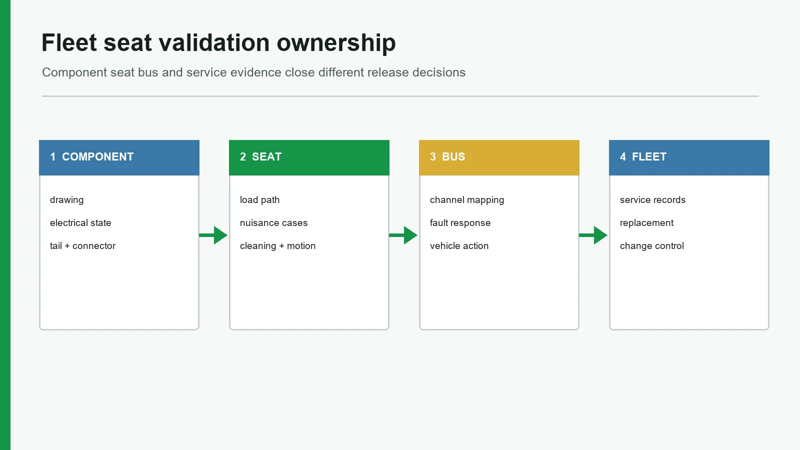
9. Validate the Component, Seat, Bus, and Fleet Separately
Each evidence layer closes a different decision. A component press test cannot prove cushion behavior; a working seat cannot prove channel mapping; a correctly mapped bus cannot prove a fleet reporting method. The JASPER testing and validation planning page can support a component evidence discussion, but the project must assign all four layers.
| Layer | Release question | Example evidence | Useful references | What it does not prove |
|---|---|---|---|---|
| Sensor component | Does the released part produce the specified electrical observations? | Drawing, circuit, dimensional record, zone checks, tail/connector checks, lot sampling | Applicable ISO 19642 cable-product part and its Part 2 method, only when lead construction and voltage fall within scope | Installed cushion behavior |
| Production-intent seat | Does the full stack detect required cases and reject defined nuisance cases? | Seat builds, load positions, cleaning, motion, trim removal, replacement | ISO 16750-3:2023 mechanical, -4:2023 climatic, and -5:2023 chemical conditions; SAE J1455 only when selected by the program | Vehicle channel mapping or fleet data |
| Bus integration | Are seat IDs, branches, controller inputs, faults, recovery, and configuration correct? | Mapping test, open/short/swapped branch, power/reset, diagnostic and service records | OEM electrical requirements; ISO 26262 process only if allocated to a safety-related E/E function | APC, privacy, or NTD reporting quality |
| Fleet pilot | Do work instructions, maintenance, configuration, and intended outputs remain usable in service? | Inspections, pilot records, replacements, recurrence analysis, controlled corrective action | FTA maintenance-monitoring methods; APTA procurement documents | Universal life or another fleet's result |
ISO 16750-3, -4, and -5 support selection of mechanical, climatic, and chemical conditions for an E/E component at its installation location. ISO 16750-2 addresses vehicle electrical loads, while ISO 16750-1:2023 confirms that the series does not cover electromagnetic compatibility. These parts do not qualify a complete seat or supply universal severities, sample counts, sequences, or acceptance criteria. Likewise, SAE J1455 is a Recommended Practice for heavy-duty vehicle test planning, including buses; naming it is not evidence that a part passed it.
For U.S. Projects, FMVSS No. 302 may apply to a sensing layer incorporated into a listed seat component depending on the material, bonding, location, and finished configuration; it does not create an “FMVSS-certified sensor.” FMVSS No. 222 governs affected school-bus seating systems but does not mandate an occupancy mat. FTA Bus Testing under 49 CFR Part 665 is a bus-model eligibility process for covered federally assisted acquisitions, not standalone component approval.
In UNECE type-approval markets, the Contracting Party, vehicle category and class, approval unit, and amendment series control applicability. UN R107 covers general M2/M3 bus construction but excludes vehicles specially designed for schoolchildren; UN R118 and UN R80 concern defined fire-performance and seat/anchorage-strength scopes rather than occupancy detection. UN R174 matters only if the signal supports a covered safety-belt reminder. An active controller or electrical/electronic subassembly may bring UN R10 into scope; a passive mat is not automatically R10-approved.
The verification matrix names method, severity, operating state, fixture, specimen count, sequence, acceptance limit, owner, and report.
A response says “automotive grade,” “ISO tested,” or “bus life” without those fields.
10. Lock Production Evidence and Change Triggers
Release the drawing, bill of materials, circuit, approved seat stack, installation work instruction, connector, packaging, inspection plan, retained reference, traceability fields, and deviations together. Define which changes require document review, a seat build, partial retest, or complete revalidation: foam, trim, frame, active zone, film, spacer, adhesive, ink, tail, lead, connector, controller circuit, cleaner, assembly site, and seat supplier are common triggers.
JASPER holds ISO 9001, ISO 13485, IATF 16949, and ISO 14001 certifications. These management-system certifications are supplier evidence, not proof of the durability, threshold, regulatory status, or vehicle approval of a bus passenger seat sensor. When site or scope applicability is material to supplier approval, request the current certificate copies from JASPER sales.
APTA's current Standard Bus Procurement Guidelines provide a structured RFP template for 35–60 ft transit and commuter buses. They are a voluntary procurement framework, not a component certification. The useful lesson is contractual: open assumptions need named owners and evidence before award.
A change matrix connects each controlled characteristic to notification, approval, and revalidation action.
A golden prototype passes, but no record defines what production must keep equivalent.
Run a Six-Step Buyer and Sample-Approval Process
The buyer process should narrow uncertainty in sequence. It begins with the fleet decision and ends with controlled production and service—not with an unqualified catalogue part.
Step 1 — Freeze the Seat-State Contract
Name every seat or zone, the required observation, valid states, faults, consumers, owners, and actions. Decide whether baggage, kneeling, a folded cushion, a removed seat, and a disconnected branch should read empty, occupied, unknown, unavailable, or fault. If stakeholders cannot agree on that table, do not request mat geometry yet.
Step 2 — Issue One Controlled Input Package
Send the production-intent cushion section, trim and foam revisions, frame/support drawing, passenger-zone map, moving-seat states, tail direction, connector and circuit, cleaner list, service procedure, nuisance cases, vehicle environment, sample quantities, and proposed validation layers. Mark unknown fields rather than filling them with supplier assumptions.
Step 3 — Compare Architectures Against Stop Conditions
Score contact, analog pressure, capacitive, structural, and non-seat options against the observation, seat load path, object-discrimination need, diagnostics, power, service, and system ownership. When a stop condition applies, reject the option. Record why. “Thin and inexpensive” is not a complete decision.
Step 4 — Approve the Component and Representative Seat Builds
Inspect drawings, circuit behavior, dimensions, active zone, tail, connector, and samples before installing several production-intent seats. Exercise required passenger and nuisance cases, cleaner exposure, seat motion, trim removal, cable strain, disconnects, and replacement. Preserve raw data and failed setups; an adjusted threshold should not erase the cause.
Step 5 — Verify Bus Mapping and Run a Bounded Fleet Pilot
Confirm every seat ID, harness branch, controller channel, valid state, fault, recovery, and configuration. A pilot then tests installation and maintenance procedures under controlled scope. Define the duration, vehicles, seat variants, inspection points, event fields, acceptance limits, escalation rule, and owner before operation begins; do not convert an open-ended trial into a hidden release test.
Step 6 — Release Production, Service, and Change Control Together
Approve the part and seat drawings, bill of materials, work instructions, inspection plan, packaging, labels, traceability, service replacement, recommissioning, and change matrix as one package. The release authority should know which deviations require notification, seat-level checking, vehicle regression, or a new pilot.
Sample-Approval Checklist
| Approval item | Evidence to retain |
|---|---|
| Seat identity | Seat and zone IDs match the vehicle layout and harness map |
| State contract | Empty, occupied, unknown, fault, and out-of-service behavior |
| Revision alignment | Sensor drawing and electrical interface use the same revision |
| Production stack | Released foam, trim, support, retention, and tail exit |
| Challenge cases | Passenger, baggage, edge, kneeling, folded, removed, and fault records |
| Cleaning | Cleaner, application, wet time, repetition, drying, and inspection |
| Layered approval | Component, seat, bus, and fleet records name owner and release authority |
| Service recovery | Replacement and recommissioning restore the correct seat ID and state |
| Change control | Material, process, seat, harness, controller, and cleaner triggers |
Release Blockers That Disqualify a Design or Supplier Response
These release blockers override an attractive sample or a long specification sheet because they leave the installed decision unverifiable.
- One universal force or cycle value for every seat — Cushion geometry, support, installation, and acceptance cases are missing.
- “Automotive grade” without a test report — No method, severity, mounting location, specimen, operating state, or result is named.
- An IP code with no enclosure boundary — The claim does not identify whether it covers the mat, splice, connector, interface, or complete seat.
- No unknown or fault state — Disconnection, removal, and misconnection can masquerade as a valid empty seat.
- A cable route supplied after sample approval — The most exposed transition is excluded from the approved design.
- Threshold tuning without raw evidence — The physical cause of a false state remains unresolved.
- A component sample treated as vehicle approval — Seat integration, mapping, diagnostics, and regulatory responsibility are unassigned.
- No change or recommissioning plan — Production substitutions and field replacement can silently invalidate the approved setup.
Frequently Asked Questions
What does bus seat occupancy sensor design include?
Bus seat occupancy sensor design includes the required seat state, sensing architecture, passenger zone, cushion load path, installation, electrical interface, tail and harness route, cleaning exposure, nuisance cases, diagnostics, validation layers, production controls, and service replacement. Mat outline is only one part of the released seat node.
Is a fleet seat pressure mat the same as an automatic passenger counter?
No. A fleet seat pressure mat reports a local seat observation. The FTA defines an APC around boarding and alighting counts, while UPT and PMT require trip and distance context. A seat-state map may support customer analytics, but it is not by itself an APC or an NTD reporting method.
Which bus passenger seat sensor architecture is best?
No architecture is universally best. A contact mat fits a simple binary state with a repeatable cushion load path. Analog or multi-zone pressure sensing fits richer load information; capacitive sensing may support classification; structural sensors fit controlled frames; and optical or door systems fit passenger-flow questions. Select against the required observation and stop conditions.
How can a bus seat sensor avoid false occupied and false empty states?
Define representative passenger and nuisance cases before tuning. Test centered, edge, leaning, kneeling, baggage, wet, folded, removed, disconnected, shorted, and swapped-branch conditions in the production seat. Preserve the raw signal and setup, then decide whether geometry, load path, installation, circuit, state logic, or threshold caused the error.
How should a bus seat sensor cable be routed?
Route the tail and lead outside passenger pressure, sharp edges, hinges, moving brackets, floor hardware, cleaning tools, and technician pull paths. Define support, strain relief, allowed bend zones, connector retention, keying, labels, branch identity, and service access. Verify the route in every seat position and during cushion replacement.
How should cleaning be validated for a fleet seat pressure mat?
Test the actual cleaner and work instruction on a production-intent seat. Record concentration, application, wet time, amount, direction, repetitions, rinse, drying, temperature, and access state. Inspect electrical behavior, retained liquid paths, adhesive, tail, connector, and recovery. An IP code alone does not establish chemical compatibility.
Does FMVSS No. 222 certify a school bus seat occupancy sensor?
No. FMVSS No. 222 is a school-bus passenger-seating and crash-protection vehicle standard; it neither requires an occupancy sensor nor creates component approval. Its “fixed occupancy” and “flexible occupancy” terms describe belted bench-seat configurations, not occupancy sensing. The vehicle manufacturer self-certifies the completed vehicle. FMVSS No. 302 applicability can separately depend on the sensing material, bonding, location, and finished cushion configuration.
Do U.S. seat-belt reminder rules require occupancy mats on every bus seat?
No. NHTSA's April 2026 FMVSS No. 208 interim final rule covers specified buses at or below 4,536 kg (10,000 lb) GVWR from 2028-09-01; multi-stage manufacturers and alterers receive one additional year. The rear-seat provision excludes school buses and law-enforcement vehicles, and the minimum rear warning can rely on buckle status without occupant detection. Check the exact vehicle, seat, date, and jurisdiction.
What evidence should be approved before bus-seat sensor production?
Approve the component drawing and circuit, production seat build, zone and installation record, passenger and nuisance results, cleaning and environmental evidence, harness route, connector, vehicle mapping, fault and recovery tests, work instructions, packaging, traceability, service replacement, recommissioning, and change triggers. Each record needs an owner and release authority.
When is a flexible seat mat the wrong choice?
A flexible mat is the wrong choice when the project needs FTA-approved APC data for NTD reporting, repeatable person-versus-object classification, structural weighing, or a complete ECU/display/telematics system. Stop as well when the seat cannot provide a repeatable load path, the lead cannot be protected, or service cannot occur without damaging the sensing element.
Discuss a Fleet Seat Sensing Project
Prepare one controlled package: seat and cushion drawings, passenger-zone map, required states, electrical interface, tail and harness route, connector, cleaner and service procedures, nuisance cases, validation responsibilities, annual build assumptions, and change controls. Then discuss the fleet seat sensing project against the architecture stop conditions before releasing geometry.
JASPER can review a custom flexible sensing element, active zone, interconnect, component evidence, and repeated-seat production inputs. A seat-system or vehicle integrator is the stronger choice when the scope includes controller logic, a driver display, telematics, APC reporting, functional-safety ownership, or complete-vehicle approval. Related context is available in the car seat occupancy sensor family, the seat-belt reminder sensor boundary, and JASPER's automotive application overview.
Technical References
- Source: Federal Transit Administration National Transit Database definitions. Accessed 2026.
- Source: APTA Standard Bus Procurement Guidelines. Accessed 2026.
- Source: SAE J1455 heavy-duty vehicle environmental practices. Accessed 2026.
- Source: ISO 16750 road-vehicle environmental conditions. Accessed 2026.
- Source: NHTSA school bus regulations guidance. Accessed 2026.
- Source: FTA glossary. Accessed 2026.
- Source: guide to monitoring operations and maintenance procedures. Accessed 2026.
- Source: Molex user-interface brochure. Accessed 2026.
- Source: Interlink FSR Integration Guide. Accessed 2026.
- Source: ISO 16750. Accessed 2026.
- Source: SAE J1455. Accessed 2026.
- Source: Bus Seating Information Technology study. Accessed 2026.
- Source: University of Pretoria project. Accessed 2026.
- Source: green-minibus proof-of-concept plan. Accessed 2026.
- Source: 2026 NTD manual. Accessed 2026.
- Source: capacitive occupancy classification. Accessed 2026.
- Source: ISO 19642-2:2023. Accessed 2026.
- Source: APTA cleaning white paper. Accessed 2026.
- Source: ISO 16750-5:2023. Accessed 2026.
- Source: ISO 20653:2023. Accessed 2026.
- Source: school-bus FAQ. Accessed 2026.
- Source: ISO 16750-1:2023. Accessed 2026.
- Source: FMVSS No. 302. Accessed 2026.
- Source: FMVSS No. 222. Accessed 2026.
- Source: FTA Bus Testing under 49 CFR Part 665. Accessed 2026.
- Source: UN R107. Accessed 2026.
- Source: UN R118. Accessed 2026.
- Source: UN R80. Accessed 2026.
Release the seat node for fleet service
Send the cushion build, passenger zones, cleaning process, harness route, service states, bus mapping, and validation layers.