
Integrate the overlay, circuit stack, mounting joint, windows, fasteners, cable route, and enclosure against one datum scheme and first-article checklist before tooling is released.
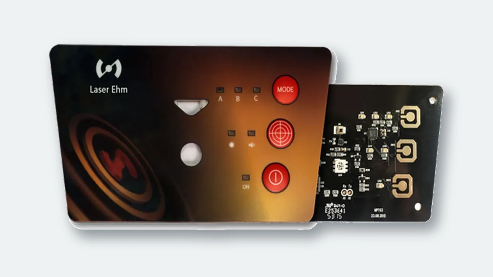
OEM mechanical and electrical teams who buy membrane switch panels often discover integration problems after the ABS, PC+ABS, or aluminum front housing is already cut. A bezel step shadows a deadfront window. A powder-coated door bows and lifts the rear pressure-sensitive adhesive (PSA) edge. Screw bosses consume land that was expected to support the enclosure seal. None of those is a pure “switch defect.” They are membrane switch panel integration failures: the PET graphic overlay, printed circuit, tactile contacts, bezel, housing, and cable path were released as separate parts instead of one controlled assembly.
This buyer guide is for engineers and sourcing leads who must release front-panel CAD and enclosure CAD together. JASPER builds membrane switch panels and related HMI stacks for industrial, medical-component, and equipment OEM programs. The criteria below stay process-agnostic: every critical dimension belongs on the controlled drawing, and every acceptance value must be supported by the selected construction, manufacturing process, enclosure, and first-article evidence.
1. Why Membrane Switch Panel Integration Decisions Fail Late
Membrane switch panel integration fails late because the switch is often treated as the last flexible sticker on a frozen plastic part. SolidWorks, Creo, or NX freezes the enclosure first. The FR4 board freezes LED and connector positions. Industrial design freezes legend colors. The membrane package is then asked to absorb every leftover millimeter. That works until the first heat-stabilized PET overlay is die-cut or laser-cut and the bezel pocket was modeled to nominal DXF lines with no clearance, no land budget, and no service path for the tail.
Four recurring failure patterns drive avoidable cost:
- Cosmetic and light leaks at the bezel. A pocket drawn to the nominal overlay outline can interfere with the real laminated stack, causing edge lift, light bleed around LED windows, or a visible buckle line.
- False electrical faults. Keys that do not remain centered over their dome or printed contact can raise resistance or create intermittent actuation. Field teams chase firmware while the root cause is an unbudgeted print-to-cut, circuit-to-cut, or enclosure offset.
- Seal land erosion. Cosmetic gap changes and late fasteners consume the continuous PSA or gasket perimeter. IEC 60529 applies IP code language to a defined enclosure configuration; a loose panel label is not an assembly test plan.
- Service and cable damage. The flexible tail is pinched at the enclosure exit, forced around an unsupported bend, or blocked by a rib that appeared after the first molded housing. Connector location can then drive the tail into a sharp edge.
Tolerance language for this work comes from ordinary mechanical design under ASME Y14.5 or the ISO GPS system, including ISO 1101 for geometrical specifications and ISO 5459 for datums. The features are still multi-process: screen printing, embossing, cutting, PSA lamination, and enclosure molding or machining. One supplier slogan cannot cover that chain. Project tolerances must be assigned from the selected processes and verified on the production-intent assembly.
The rest of this article gives a 10-point evaluation framework, a buyer process from CAD freeze to sample acceptance, and a short list of disqualifiers.
2. The 10-Point Evaluation Framework for Membrane Switch Panel Integration
Use these criteria when you review drawings, DFM notes, or supplier quotes. Each criterion includes a acceptance evidence and a release blocker.
2.1 Shared datum scheme and panel flatness
Membrane switch panel integration starts with one primary plane and secondary features both teams can measure on a vision system, CMM, optical comparator, or defined fixture. A practical primary datum may be the front face of the enclosure pocket, the bezel land, or the FR4/aluminum backer plane when the switch mounts to a rigid plate first. Secondary datums may be non-parallel pocket walls or tooling features that resolve translation and rotation. The datum system must follow the actual assembly sequence rather than whichever features are easiest to dimension in isolation.
Panel flatness is not optional language. E-coat, powder coating, molding, machining, and fastener loading can leave a mating face with local high spots or overall bow. Define the permitted flatness or assembled gap on the enclosure drawing and measure the finished surface before blaming the PSA. The related membrane switch tolerance stack-up must use the same datum frame.
Enclosure and switch drawings share the same ASME Y14.5 or ISO 1101 datum reference frame; flatness or max gap is called out on the mating face.
Only overall length/width tolerances; “industry standard fit” with no datum balloons.
2.2 Membrane switch bezel design (step, land, radius, interference)
Membrane switch bezel design is the geometry that frames the active overlay: pocket depth, step height, land width under the overlay edge, corner radii, and every undercut or rib that can touch the stack. There is no responsible universal pocket clearance. The drawing value depends on the measured laminated stack, outer-cut process, housing material, temperature range, installation path, and the visual gap the product can accept.
| Bezel decision | Required project input | First-article evidence |
|---|---|---|
| Pocket clearance | Outer-cut capability, housing tolerance, thermal movement, install direction | No edge interference or uncontrolled visible gap |
| Corner geometry | Housing radius and switch cutting method | Switch seats without corner buckle or lifted adhesive |
| Step height and land | Measured stack, rear mount, gasket and finish | Controlled flushness and continuous edge contact |
| Under-key ribs and bosses | Active-key map, support plane and tactile construction | Center/edge actuation on the installed assembly |
Section view shows bezel step, land width, clearance, and max stack height on one sheet.
Pretty rendering of a flush panel with no section and no land dimension.
2.3 Control panel overlay integration (windows, deadfronts, LED ledges)
Control panel overlay integration is how printed legends, selective textures, clear or tinted windows, and deadfront graphics line up with displays, LEDs, and embossed keys. Build separate tolerance contributors for print-to-cut, circuit-to-cut, display-to-enclosure, enclosure-to-bezel, and final assembly location. The supplier must state which contributors its process controls for the actual panel size and cutting method; do not collapse the chain into one registration slogan.
Windows fail in three distinct ways: geometric offset, optical mismatch such as haze or hot spots, and mechanical shadowing from the bezel ledge. Deadfront graphics that look correct on a light table can disappear or ghost after the viewing angle and installed light source change.
Separate callouts for print-to-cut, circuit-to-cut, window-to-LED, and color-to-color; measurement method named.
One tight “registration” value with no breakdown by feature, panel size, cutting method, or inspection fixture.
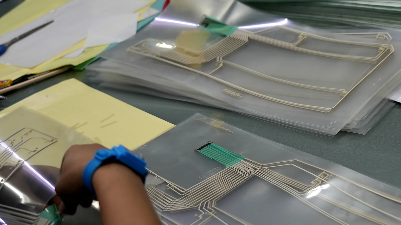
2.4 Membrane panel mounting method selection
Membrane panel mounting is the joint that holds the finished switch to the product. It is not always “peel and stick.”
| Mounting method | Typical use | Main risks if mismatched |
|---|---|---|
| Rear PSA selected for the actual substrate | Flat, clean, continuous land with verified surface preparation | Edge peel on texture, bow, contamination, or short land |
| PSA + rigid backer (aluminum or FR4) | Standalone sub-panel; needs stiffness | Thickness stack vs bezel; thermal mismatch |
| Mechanical retainers / clamps / bezel compression | Serviceable panels; thick gasket stacks | Crush of domes; uneven compression |
| Fastener-retained plate or frame | High vibration, thick doors, replaceable modules | Screw bosses invade seal path; warp |
| Hybrid (PSA + selective fasteners or gasket) | Washdown industrial HMI | Over-constrained stack; leak at fasteners |
Adhesive selection must follow the current product data sheet, substrate surface energy, finish texture, cleaning process, temperature exposure, and available land. Adhesives used inside the circuit as spacers or dome retainers are not automatically suitable as the rear mount to a textured enclosure. Use the project-specific membrane switch adhesive selection record to separate those roles.
Mounting method stated with substrate, surface energy class, land width, and service plan.
A brand name or “strong tape” as the only mount note on a bowed or textured door.
2.5 Edge land, adhesive continuity, and gasket path
Edge land is the continuous area available for rear PSA or a gasket. Cosmetic gap fights seal land. If the assembly targets an IP code under IEC 60529, the perimeter, windows, fasteners, vents, and tail exit must be designed and tested as one enclosure configuration. A continuous tail-exit closure may be part of that design, but it is not an IP result by itself.
Gasket materials belong in the same budget when the bezel compresses foam or silicone. Material family, compression range, compression set, chemical exposure, joint width, and fastener loading must be resolved together on the assembly drawing.
Minimum continuous land called out; adhesive-free zones for windows/vents/tail marked; gasket squeeze concept documented if used.
An IP code on the RFQ with discontinuous land, open paths, and no defined test article.
2.6 Fastener map versus seal path
Fasteners fix doors and bezels. They also create leak paths, local warp, and adhesive starve-out. Map every screw, stud, and snap relative to:
- Seal land and gasket.
- Active keys (boss under a dome).
- Display window (stress whitening on PC).
- Tail exit.
A fastener pattern that looks acceptable for structural stiffness can pull a panel into local high and low spots that a thin adhesive layer cannot follow. Inspect the clamped assembly, not only the free-state door.
Fastener schedule on the same drawing as seal land; torque/process note owned by the enclosure team.
Screws added after switch DFM “to stop peeling.”
2.7 Cable route, tail exit, and connector float
The tail is where otherwise clean front panels fail in the field. Exit slots need clearance for the finished circuit, rear adhesive, stiffener, connector insertion path, and assembly variation. The minimum bend radius, conductor width/spacing, bend-zone neck-down, and strain relief differ between printed silver PET and etched copper flex constructions. Use the applicable IPC-2223 design context plus the selected circuit supplier's controlled process rules. Connector location must not drive the tail into a sharp enclosure edge.
3D or section path for the tail; strain relief; connector family matched to vibration environment.
Tail drawn as a straight ribbon with no exit clearance and no bend note.
2.8 Service access and field-replace path
Membrane switch panel integration includes the second technician, not only the first assembly line. Can the panel be removed without destroying the enclosure paint? Is the connector accessible without dropping the door into the electronics bay? Is there a liner-split or tab that allows controlled peel? Service access is part of membrane panel mounting: a permanent high-bond rear PSA on a field-replace panel is often the wrong construction.
Service sequence written (tools, peel direction, spare panel P/N strategy).
“Customer will never replace the keypad” as the only plan on a long-service industrial asset.
2.9 Environmental claim honesty (system view)
IEC 60529 classifies degrees of protection provided by enclosures under defined conditions. Spray, immersion, and dust claims therefore belong to the assembly, including gasket, fasteners, window bonds, vents, and tail exit—not to a loose overlay coupon. Temperature, UV, cleaning chemistry, oil exposure, impact, and required flexing still drive overlay and adhesive selection. Record the named material, thickness, finish, test configuration, and acceptance method instead of relying on a generic “waterproof panel” label.
Environmental requirements listed as system tests with sample definition; materials chosen against that list.
“Waterproof membrane switch” checkbox with no enclosure drawing attached.
Standards and evidence shelf
| Reference | Role in the integration package | Boundary |
|---|---|---|
| ASME Y14.5 | Datum and tolerance language for ASME-based drawings | Does not supply project capability values |
| ISO 1101 | Geometrical specification vocabulary in ISO GPS drawings | Values still belong on the controlled drawing |
| ISO 5459 | Datum and datum-system framework | Datum features must match the assembly function |
| IEC 60529 | Enclosure IP code language | Applies to the defined test configuration |
| IPC-2223 | Flexible printed board design context for the tail | Construction and process rules remain supplier-specific |
2.10 Drawing package and sample acceptance gates
Integration is not approved by a phone photo of a sample on a desk. Require a package that mechanical, electrical, and graphic owners can share:
| Package item | Why it exists |
|---|---|
| Enclosure + bezel 2D/3D with datums | Shared measurement frame |
| Switch outer cut DXF/DWG | Pocket and land check |
| Window / LED / display openings | Control panel overlay integration |
| Circuit + pinout (Gerber or equivalent) | Electrical mate |
| Layer stack BOM with thicknesses | Bezel step and connector slot fill |
| Adhesive / gasket callouts by role | Mount and seal |
| Tail path + connector P/N | Cable route |
| Artwork with Pantone / hard-coat notes | Visual acceptance |
| Sample measurement checklist | FAI, not “looks good” |
Use a release package that keeps DXF/DWG geometry, Gerber data, color PDFs, the BOM, and the revision log under the same controlled project record.
Written sample approval checklist shared before build; linked revision control when enclosure or artwork changes.
Artwork Rev C ships into Rev A pockets with no re-measure.
3. Step-by-Step Buyer Process (CAD Freeze to Accepted Panel)
This sequence turns the framework into a job a mechanical engineer and a buyer can run on one thread.
Step 1 — Freeze front-panel and enclosure CAD together
Before RFQ, mark primary and secondary datums on the enclosure and on any rigid backer. Export pocket depth, bezel step, land width, rib map under keys, window ledges, fastener positions, and tail exit slot width/height. If the real mounting plane is an FR4 plate inside a front panel HMI assembly, name that plane as datum A explicitly. Membrane switch bezel design cannot start from Illustrator alone.
Step 2 — Draw the integration loop on one sheet
Enclosure / bezel primary datum
pocket wall & land (± mold / machine)
membrane outer cut (± cut process)
print registration to cut (control panel overlay integration)
keys / windows / deadfronts
circuit pad / dome center
rear mount (PSA / plate / fasteners)
seal land or gasket path
tail exit vs slot & connector float
service peel / replace path
That diagram is membrane switch panel integration in one view.
Step 3 — Choose membrane panel mounting before artwork polish
Decide PSA-only vs backer vs fastener-retained vs gasketed bezel while the land still exists in CAD. Select the rear mount from the actual substrate, surface energy, finish texture, cleaning process, environment, and service plan. If the door is not flat, correct the mating surface or change the mount; “stronger tape” is not a substitute for a controlled joint.
Step 4 — Issue the RFQ with a real drawing package
Include the table in §2.10. Ask suppliers to return the cutting and printing process, documented capability for the actual panel size and feature class, adhesive role map, and a red-line of bezel interference. Ask how the first article will be measured and fixtured.
Step 5 — Prototype on the real enclosure finish
Bond samples to the production powder coat, texture, or anodize—not only to bare aluminum coupons. Include the real connector and the real bend path. Cycle a subset of keys; check window-to-LED alignment at operating temperature ends if the product sees wide bands.
Step 6 — First-article inspection against the shared datums
Measure gap, land coverage, window offset, key-to-dome offset, stack height at the bezel, and tail exit clearance. Record numbers. Quality testing language belongs here as process evidence (continuity, insulation, environmental checks as specified)—not as a substitute for mechanical FAI.
Step 7 — Lock change control
Any enclosure ECO that moves a rib, boss, or window ledge reopens the loop. Any artwork ECO that moves a window reopens registration. Require re-FAI when datums or critical features move.
4. Release Blockers That Disqualify a Supplier or a Design Package
These override an attractive unit price.
- No shared datums — only one overall tolerance on a multi-window panel.
- Pocket = exact artwork outline — zero clearance, no MMC/LMC thinking under ASME Y14.5.
- IP claim without enclosure — “IP67 switch” on a loose part RFQ (conflicts with IEC 60529 system framing).
- Single tape callout for every layer and the enclosure — no stack roles.
- Tail with no exit geometry — straight ribbon into a sharp wall.
- Fasteners added after peel failures — no seal-land map.
- Universal key-size rules treated as laws — no operator or glove context.
- Verbal sample approval — no measured FAI.
- Refusal to red-line the bezel section — integration is treated as artwork only.
- Capability slogans without process — a tight value claimed for every feature and panel size without measurement evidence.
5. Frequently Asked Questions
What is membrane switch panel integration?
Membrane switch panel integration is the engineered fit of the membrane assembly to bezels, windows, mounts, fasteners, cable exits, and the enclosure so mechanical, electrical, and sealing features meet one drawing set. It is larger than overlay artwork and larger than a single adhesive grade.
How does membrane switch bezel design affect reliability?
Membrane switch bezel design sets pocket clearance, land width, step height, and corner radii. Too tight buckles PET and lifts PSA; too loose creates gaps and light leaks; ribs under keys create false actuation. Section views matter more than front renderings.
What is control panel overlay integration?
Control panel overlay integration aligns legends, deadfronts, and clear windows to LEDs, displays, and embossed keys under a shared datum. It budgets print-to-cut and circuit-to-cut offsets, not only Pantone color.
Which membrane panel mounting method should OEMs choose?
Choose membrane panel mounting from the housing: rear PSA on flat high-energy lands; LSE-capable acrylics on many powder coats; rigid backers when stiffness is required; fasteners or gasketed bezels when service or washdown demands it. Match method to land and environment, not to catalog adjectives.
Does adhesive alone make an IP65 or IP67 panel?
No. IEC 60529 rates enclosures and defined test articles. Perimeter PSA width is one input among gasket, fasteners, windows, vents, and tail exit. Adhesive alone is not an IP rating.
What clearance is typical between panel and pocket?
There is no universal pocket clearance. Set it from the panel's outer-cut capability, enclosure tolerance, stack thickness, housing material, thermal range, installation direction, and acceptable visual gap. Confirm the proposed value on the production-intent enclosure before tooling release.
What drawings should be in the RFQ?
Enclosure/bezel 3D+2D with datums, switch cut DXF, window map, circuit/pinout, layer stack BOM, adhesive/gasket roles, tail path, connector P/N, and artwork with finishes. Include a sample measurement checklist.
When is rear-PSA-only mounting the wrong choice?
When the mating face is bowed or heavily textured, when field replace is required, when vibration needs mechanical retention, or when a gasketed bezel is the real seal. In those cases, plate, fasteners, or hybrid stacks fit better.
How should first articles be accepted?
Clamp to the shared datums, measure gap, window offset, key-to-dome alignment, stack height, and tail clearance, and record pass/fail numbers. “Looks centered” is not FAI.
6. What to Do Next
Membrane switch panel integration succeeds when bezel land, windows, membrane panel mounting, fasteners, cable route, and service access share one datum chain and one sample checklist. Use the 10 criteria above to red-line the front-panel and enclosure package before enclosure tooling or switch cutting tools are released. Do not approve a clearance, registration value, bend radius, or seal land until its process owner and first-article measurement method are named.
share the front-panel and enclosure CAD (datums, bezel section, window map, fastener schedule, tail exit, and surface finish) for an engineering review. JASPER can red-line the membrane panel interface and identify what the first article must prove. Where environmental or electrical evidence is required, define the test article and method under quality testing before production release.
Review the panel and enclosure before tooling is released
Send the front-panel and enclosure CAD, datum scheme, bezel section, window map, fastener schedule, mounting surface, tail route, and sample priorities. JASPER Engineering will mark the integration decisions that need evidence.