
An HMI panel for HVAC systems is the local hardware interface through which an occupant, technician, or building operator views conditions and changes permitted settings. The correct design depends on the task, installation tier, viewing distance, available panel area, gloves or moisture, display and touch stack, service route, physical BACnet or Modbus interface, and the party that owns commissioning. Specify the operator job first. Then release the front-panel drawing, enclosure boundary, connector state, environment, and validation plan. This guide covers manufacturable HMI hardware; PLC logic, SCADA development, control sequences, network commissioning, and whole-building performance remain system-level responsibilities.
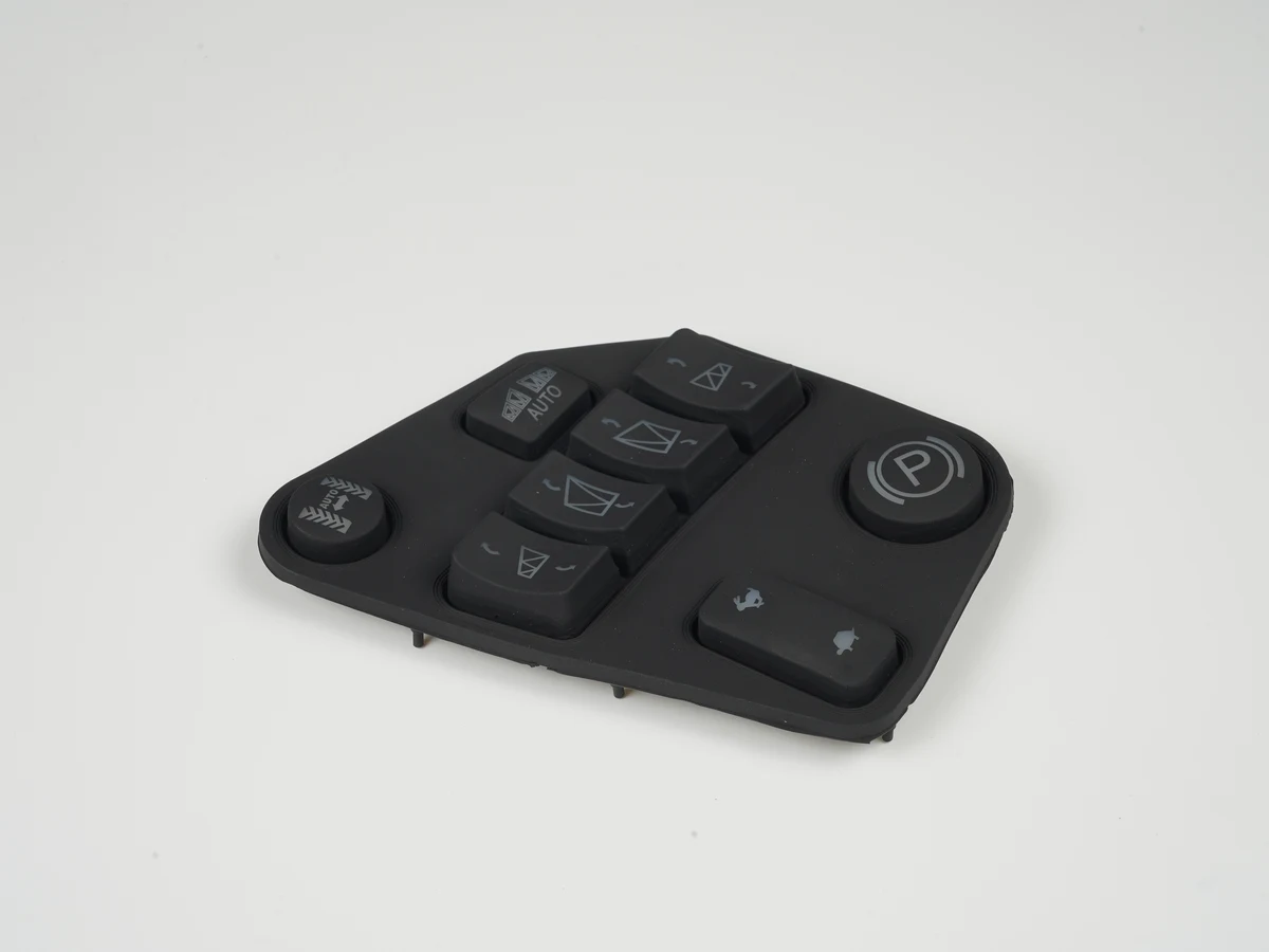
Quick decision: match the HMI hardware to the operating task
The smallest acceptable interface presents the required controls at the working distance without making service or alarm response ambiguous. A larger screen does not fix an undefined task.
| Installation tier | Primary local task | Hardware direction | Connectivity and service implication |
|---|---|---|---|
| Room or zone device | Read status; adjust occupant settings | Compact display, few touch zones or keys | Concealed wiring, cleaning, replacement |
| Equipment-mounted interface | Inspect values, faults, and service actions | Glove-compatible input or keys; sealed front | Safe access without unrelated disassembly |
| Control-cabinet door HMI | Navigate equipment, trends, alarms, schedules | Larger active area; bezel/gasket; rear clearance | Cutout, ground, heat, service envelope |
| Local supervisory panel | View systems; support commissioning | Higher-capacity display and IP hardware | Named owners for OT network, runtime, updates, remote access |
Custom HMI assemblies can combine the lens or overlay, input, display relationship, PCB or FPC, carrier, gasket, connector, and agreed checks. They do not automatically include the controller application, BMS database, cabinet certification, or site acceptance.
An HVAC HMI panel is the physical operator endpoint, not the control system
An HVAC HMI panel combines an operator surface with input, visual output, mechanical support, and electrical interfaces. It may talk directly to a controller, display a web page served elsewhere, or front a controller that runs local logic. Those architectures can look identical.
That distinction matters at quotation. A front-panel manufacturer can build an aligned, tested assembly without owning BACnet objects, Modbus registers, graphics, schedules, passwords, or control sequences. The U.S. Department of Energy describes modern building controls as networked systems that join sensing, control, and remote monitoring. The HMI is one endpoint, not the whole system (U.S. DOE building-controls overview).
For broader terminology before selecting the application-specific stack, see What Is an HMI Panel? Hardware and OEM Guide.
The manufacturable hardware stack
The released stack should show every interface from the operator surface to the customer connector. The exact construction varies, but the ownership questions remain consistent.
| Stack element | Function | Drawing or RFQ input that closes the decision |
|---|---|---|
| Graphic overlay or cover lens | Protects surface; carries graphics | Material, thickness, finish, window, cleaners, UV |
| Touch sensor or discrete input | Converts operator action | Technology; glove, moisture, force, false touch |
| Display and optical interface | Presents operator information | Module, active/viewing areas, orientation, readability, bonding |
| Adhesive, gasket, or seal | Locates layers; preserves boundary | Bond, compression, substrate, cutout, fastener load |
| Carrier, bezel, and fasteners | Holds alignment and datums | Datums, flatness, fasteners, torque, rear envelope |
| PCB, FPC, and interconnect | Routes signals, power, ground | Files, pinout, power, shielding, isolation, connector |
| Rear cover and cable exit | Protects stack; defines handoff | Strain relief, bend/ingress path, clearance, keying |
Mark every item as supplied, customer-supplied, or reference-only. A display window is not necessarily a supplied display; an Ethernet jack is not necessarily a configured BACnet interface.
How to size an HMI panel for HVAC systems
Panel size follows the highest-priority local task, simultaneous information, working distance, and front/rear envelope. Screen diagonal alone is a poor procurement input.
A room device may need current value, target, mode, and a few permitted adjustments. An equipment HMI may need faults, live values, and maintenance actions. A plant panel may need multiple equipment groups, trends, alarms, and commissioning pages. Forcing all three into one layout usually compromises at least one task.
Define these inputs before choosing the display:
- Users and permissions: occupant, operator, technician, commissioning provider, administrator
- Simultaneous content: number of values, alarms, trends, or equipment states that must remain visible together
- Working geometry: viewing distance, eye position, orientation, reach, height, surrounding hardware
- Input conditions: bare finger, glove type, wet surface, cleaning mode, physical key requirement, and accidental-contact risk
- Localization: longest required labels, unit conventions, character sets, and regulatory markings
- Mechanical envelope: outline, cutout, bezel, active area, rear depth, cable path, removal direction
Build representative screens in the longest language, then test them on the intended display at the real viewing distance and ambient light. The drawing must match the active and viewing areas; a window that clips pixels or status icons is a mechanical defect even when the software is correct.
Shared electronics can support different room and service front assemblies. Common PCB interfaces reduce redesign while separate displays, overlays, gaskets, and carriers preserve task fit.
HMI hardware selection must close the display, input, optical, and service stack together
Display, touch, overlay, grounding, and enclosure mechanics interact. Separate part selection pushes integration risk into the prototype.
Touch technology follows the operating condition
Projected-capacitive touch supports a continuous lens, but cover thickness, electrode geometry, nearby ground, water, and gloves affect tuning. Microchip AN2934 gives one design example: for an 8 mm contact, a 1 mm cover leads to a 10 mm recommended sensor width; a 3 mm cover leads to 14 mm. These are method-specific examples, not universal HVAC button sizes (Microchip AN2934).
Resistive touch suits pressure-based operation in some glove conditions, but its top surface and optics need separate durability review. Membrane or silicone keys suit functions found by feel or used when the display is dark. A mixed interface can use touch for navigation and keys for repeated service actions.
Optical decisions belong on the mechanical drawing
Name the display module, not only its diagonal. Release active/viewing areas, outline, mounts, connector, keep-outs, orientation, and revision. State whether the lens is optically bonded, perimeter bonded, retained, or air-gapped; the choice changes reflection, visible particles, repairability, and tolerances.
Specify readability against the installation. A corridor, bright mechanical room, and rooftop unit have different light and reflection conditions. Identify viewing angles, test pattern, ambient condition, and rejectable optical defects.
Service access is part of hardware architecture
A technician needs a removal path, connector access, diagnostics, and cable control that prevents a pinched flex or disturbed seal. Keep connectors away from forced bends and tools. Key confusable plugs and keep labels visible when installed.
Flexible circuits need stack-specific design, not a generic bend-radius slogan. IPC identifies IPC-2223 for flexible and rigid-flex printed-board applications (IPC board design standards). Show materials, copper, stiffeners, bend zone, static/dynamic use, installation, connector, and strain relief.
Use the HMI Panel Assembly Design Checklist to reconcile these released inputs, and use HMI Hardware Architecture for Industrial Automation when the same hardware platform also serves non-building equipment.
BACnet and Modbus support must name the physical interface and configuration owner
BACnet and Modbus are protocol families, not connector specifications. Ports prove little. State whether the HMI terminates the protocol, displays content served elsewhere, or only carries signals.
ASHRAE Standard 135 defines BACnet services, protocols, and objects. Standard 135.1 tests capabilities claimed in a Protocol Implementation Conformance Statement, including services, objects, network layer, and data links (Standard 135 resources and Standard 135.1 scope). A port alone proves none of them.
| Named interface | What the hardware team must clarify | What remains above the front-panel assembly |
|---|---|---|
| BACnet/IP | IP interface, connector, ground, power, link indication | Stack, PICS, IP setup, objects, services, security |
| BACnet MS/TP | EIA-485, two-wire bus, terminal, polarity, termination/isolation owner | MAC, baud, network, objects, services, commissioning |
| Modbus TCP | IP hardware, normally Ethernet; connector, ground, link owner | Role, register map, polling, timeouts, IP, security |
| Modbus RTU serial | RS-485/RS-232, pinout, termination, isolation, ground, topology | Role, address, baud, parity, framing, registers, timeouts |
The Modbus Organization places the application protocol at OSI layer 7 and Serial Line at layers 1 and 2. Its guide permits RS-485 or RS-232 and calls two-wire RS-485 the most common physical interface for that scope (Modbus Serial Line V1.02). “Modbus” alone leaves the handoff incomplete.
Some HVAC HMIs are browser terminals: the panel needs an IP connection and runtime, while a controller or gateway owns the building protocol. This simplifies ports but makes browser support, certificates, updates, availability, and controller compatibility explicit requirements.
Remote access needs its own owner. NIST SP 800-82 Rev. 3 describes OT segmentation by levels, tiers, or zones and possible DMZ boundaries (NIST OT security guidance). Hardware may provide ports, shielding, and antenna clearance; IT/OT teams own accounts, firewalls, certificates, updates, monitoring, and response.
For the wider controller handoff, see PLC and HMI Integration: Hardware, Signals and Interfaces.
Indoor and outdoor HVAC panels need different environmental boundaries
“Indoor” is incomplete. A room wall differs from a humid plant room, a cabinet beside drives, or a rooftop enclosure exposed to sun, rain, ice, and chemicals.
IEC 60529 defines the IP Code. NEMA Type ratings address broader conditions, and NEMA states that IP ratings are not substitutes for enclosure Type ratings in the U.S. installations it references (IEC 60529 and NEMA enclosure FAQ). Do not reverse-convert IP to NEMA Type.
A component label does not describe an untested installation. UL 50/50E accessory evaluation considers corrosion, UV degradation, and sealing against the mounting surface (UL enclosure-accessory guidance). The HMI boundary includes lens, bond/gasket, cutout, surface, fasteners, cable exits, vents, and service doors.
Outdoor and equipment-mounted projects should also state:
- installed operating/storage temperatures, solar load, nearby heat, transitions, dwell, powered state, and acceptance criteria;
- condensation, rain, spray, dust, UV, corrosion, cleaners, and ice as applicable;
- gloves, wet/false touch, physical-key fallback, impact, vibration, shock, cable pull, and transport;
- post-exposure readability, touch, adhesive, seal, and connector requirements.
IEC 60068-2-14:2023 tests the effect of specified ambient temperature changes; it does not choose endpoints, transition, dwell, power state, or pass/fail criteria (IEC temperature-change method). Apply project conditions to a representative installed assembly.
The application-risk matrix should drive design controls and evidence
Most HVAC HMI risks sit at interfaces: wrong task, unrepresentative seal test, undefined serial wiring, or sample approval before commissioning ownership.
| Risk or failure path | Likely field consequence | Design control | Evidence and owner |
|---|---|---|---|
| Panel tier misses task | Hidden alarms; poor service flow | Task map; representative screens | OEM approves use/access states |
| Display/window misregisters | Clipping, parallax, poor readability | Shared datums; exact module; installed sample | Supplier/OEM inspect assembly |
| Touch tuning omits final stack/condition | Missed or false touches | Tune production stack; define wet/glove states | Touch owner validates |
| Gasket/bond changes at enclosure | Ingress, lift, stress, gap | Control surface, cutout, compression, fasteners | Panel builder validates boundary |
| Serial wiring rules are absent | Intermittent MS/TP or RTU | Interface and field-wiring drawings | Integrator verifies bus |
| ESD/EFT disturbs panel | Reset, false input, lost link | Ground, shield, filter, protection, recovery | Product owner sets method/criteria |
| Rear service path is absent | Damaged flex, cable, or seal | Access, keying, service loop, strain relief | OEM runs service trial |
| Remote access lacks ownership | Exposure, update/recovery failure | Zone, identity, certificate, update, log, recovery | IT/OT owns operation |
| Sample precedes commissioning plan | Hardware passes; site behavior fails | Responsibility matrix; functional test plan | Integrator/commissioning authority close behavior |
IEC 61000-4-2:2025 covers operator/nearby-object ESD; IEC 61000-4-4:2012 covers repetitive fast transients on supply, signal, control, and earth ports. The product specification must choose severity and acceptance criteria (IEC ESD method and IEC EFT/burst method).
Validation and commissioning must have separate owners
Manufacturing validation checks the released HMI boundary. Commissioning checks the installed building system against project requirements. They are not substitutes.
ASHRAE/IES Standard 202-2024 defines commissioning roles and a framework for documents, procedures, reports, and training. DOE guidance defines HVAC commissioning around installed-system verification against design documentation (ASHRAE commissioning resources and DOE HVAC commissioning).
| Decision or evidence | Primary owner | Required handoff |
|---|---|---|
| Tasks, permissions, environment, product requirements | OEM design authority | Requirements, drawings, use cases, criteria |
| Front stack, display, carrier, circuits, connector, assembly | HMI supplier within quote | BOM/drawings, sample, inspection/function records |
| Cutout, mounting, compression, field wiring, panel work | Panel builder/equipment maker | Interface drawing, assembly instruction, evidence |
| Protocol, PICS/register map, firmware/runtime, updates | Controller/software supplier | Versioned documents and files |
| Points, network, graphics, alarms, schedules, integration | Controls integrator | Database, tests, backups, as-builts |
| Requirements, functional tests, training, acceptance | Commissioning authority/owner | Plan, tests, issues, report, O&M handoff |
| Zones, remote access, identities, certificates, logging, recovery | Owner’s IT/OT team | Approved architecture and procedures |
Use production-equivalent samples for fit, optics, touch, sealing, cabling, and service. Environmental and EMC verification should reproduce the mounted state. Agreed production checks may cover appearance, dimensions, continuity, inputs, display, connector, labels, and fixture fit. Site tests close values, commands, alarms, communication loss, schedules, permissions, remote paths, and recovery.
Plan testing and validation planning around the released assembly boundary. Use prototyping and sample approval to close fit and interface risks before tooling and volume production.
A custom HVAC HMI assembly is not always the right answer
Choose a standard controller or operator terminal when its dimensions, rating, protocol, approvals, lifecycle, and user experience fit. Custom hardware adds value for a branded front, unusual envelope, mixed touch/keys, defined display integration, or controlled mounting and connector handoff.
A custom front cannot prove BACnet conformance or make an industrial control panel compliant by itself. It cannot replace equipment certified for a hazardous location, and a display-only control should not be the sole means of a required safety function. Route those requirements to product, panel, controls, safety, and certification owners before tooling.
Project-input checklist for an HVAC and building-controls HMI
Before RFQ, provide enough information to expose missing ownership. The first package does not need final artwork, but it should contain the decision-driving interfaces.
- [ ] Installation tier and local tasks: room, equipment, cabinet, or supervisory
- [ ] Users, permissions, alarm/service actions, physical-key requirements
- [ ] Display model/size, active/viewing areas, optical stack, installed readability
- [ ] Front outline, cutout, datums, artwork, input map, finish, enclosure model
- [ ] Touch stack, cover, glove/moisture states, ground/shield, tuning owner
- [ ] PCB/FPC, flex path, stiffeners, connectors, pinout, power, isolation, test access
- [ ] BACnet/Modbus role, data link/transport, physical interface, protocol/configuration owners
- [ ] Environment, temperature profile, condensation, UV, ingress, chemicals, mechanical/EMC criteria
- [ ] Carrier, gasket, fasteners, mounting, compression/torque owner, clearance, service direction
- [ ] Prototype quantity, annual volume, checks, traceability, packaging, change/requalification rules
- [ ] Owners for manufacture, panel, firmware, integration, OT security, commissioning, approval
OEM teams can send drawings for engineering review with the display size, front-panel drawing, interface stack, environment, and annual volume. If the supply boundary is clear enough to price, request an engineering quote.
Frequently Asked Questions
What hardware should an HMI panel for HVAC systems include?
An HMI panel for HVAC systems should include only the hardware assigned in the released supply boundary: typically an overlay or lens, touch sensor or keys, display or display window, carrier, gasket, PCB or FPC, interconnect, connector, mounting features, and agreed checks. Controller software, BMS graphics, point mapping, and commissioning require separate ownership.
How large should an HVAC HMI screen be?
Choose the screen after defining the local task, simultaneous information, viewing distance, gloves, language, panel envelope, and rear service space. A room setpoint device may need only a compact display; a plant supervisory panel may need trends and alarm navigation. Validate representative screens on the intended display under installed lighting before release.
Does a BACnet HMI need Ethernet or RS-485?
It depends on the BACnet data link and the HMI architecture. BACnet/IP requires an IP-capable path, commonly Ethernet at a panel. BACnet MS/TP uses an EIA-485 field bus. A browser HMI may use Ethernet only while a separate controller terminates BACnet. State the data link, connector, isolation, termination, and protocol owner.
What is the difference between Modbus RTU and Modbus TCP hardware?
Modbus RTU commonly runs over a serial physical interface such as two-wire RS-485, so the design must define transceiver, terminals, polarity, isolation, grounding, and termination. Modbus TCP uses an IP network, normally Ethernet at the HMI. Both still need an assigned client/server role, addressing, register map, timeout behavior, and commissioning owner.
Is an IP65 front enough for an outdoor HVAC panel?
No. A front-component rating does not prove the installed outdoor enclosure boundary. The lens or overlay, gasket or bond, panel cutout, mounting surface, fasteners, cable exits, vents, and rear enclosure must be evaluated together. The project must also address UV, temperature change, condensation, corrosion, ice, cleaning, service access, and the required U.S. enclosure Type where applicable.
When are physical keys better than a touchscreen for HVAC controls?
Physical keys are often better for repeated service actions, operation by feel, defined glove conditions, or a deliberate fallback when touch behavior under moisture is difficult to control. Touch remains useful for navigation and dense information. A mixed interface can reserve keys for critical repeated actions while keeping configuration and trends on the display.
Who owns BACnet point mapping and commissioning?
The controls contractor or system integrator normally owns BACnet point mapping, device and network configuration, graphics binding, alarms, schedules, and integration tests. The commissioning authority and facility owner own functional acceptance against project requirements. An HMI assembly supplier owns only the physical and electrical checks listed in its released manufacturing scope.
What files should an OEM send for an HVAC HMI quote?
Send the front-panel and enclosure drawings, display model or size, overlay/lens artwork, touch or key map, PCB/FPC and connector details, physical BACnet/Modbus interface, environmental and validation conditions, prototype quantity, annual volume, and responsibility matrix. Mark supplied, customer-supplied, reference-only, software, commissioning, and certification items separately.
References
- U.S. Department of Energy, About Building Controls, accessed August 24, 2026.
- ASHRAE, Standard 135 BACnet resource files and Titles, Purposes, and Scopes for Standards 135-2024 and 135.1-2023, accessed August 24, 2026.
- Modbus Organization, MODBUS over Serial Line Specification and Implementation Guide V1.02, December 20, 2006.
- National Institute of Standards and Technology, NIST SP 800-82 Rev. 3: Guide to Operational Technology Security, September 2023.
- International Electrotechnical Commission, IEC 60529: Degrees of protection provided by enclosures, consolidated publication with amendments through 2013.
- National Electrical Manufacturers Association, NEMA Enclosure FAQ, accessed August 24, 2026.
- UL Solutions, Environmental-Rated Accessories for Enclosures, accessed August 24, 2026.
- Microchip Technology, AN2934 Capacitive Touch Sensor Design Guide, 2020.
- IPC, Board Design Standards, accessed August 24, 2026.
- International Electrotechnical Commission, IEC 61000-4-2:2025 ESD immunity test, 2025.
- International Electrotechnical Commission, IEC 61000-4-4:2012 EFT/burst immunity test, April 30, 2012.
- International Electrotechnical Commission, IEC 60068-2-14:2023 change-of-temperature tests, July 27, 2023.
- ASHRAE, Commissioning resources and ASHRAE/IES Standard 202-2024, accessed August 24, 2026.
- U.S. Department of Energy, HVAC Commissioning, accessed August 24, 2026.
- BACnet Committee, BACnet Technical FAQs, accessed August 24, 2026.
- UL Solutions, UL 508A Supplement SA Specific Component Requirements, October 2025.
Bring the drawing, stack and operating conditions
JASPER engineering will review the interfaces, open risks and evidence required for a production quote.