
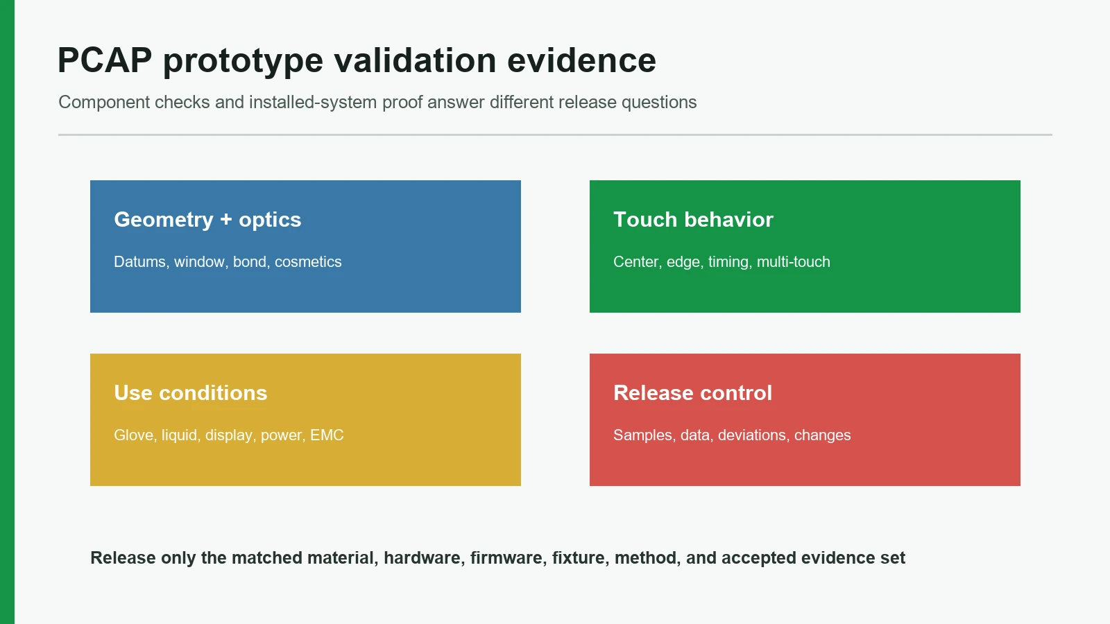
A capacitive touch panel prototype validation review should approve a named production-intent stack—not a loose panel that responds to one finger. OEM teams need recorded evidence for geometry, optics, full-area touch response, edges, multi-touch, gloves, water, electrical noise, bonding, cosmetics, environment, host behavior, and revision control before the sample becomes the production baseline.
This checklist is for mechanical, electronics, firmware, quality, and sourcing teams reviewing a custom PCAP sample. It separates panel inspection from finished-equipment validation and shows what each approval record should contain. JASPER is one possible source for PCAP touch panels, but supplier choice does not change the evidence standard. The article does not set universal limits for accuracy, gloves, water, EMC, cosmetics, life, or ingress protection.
Why a finger test is not PCAP prototype approval
A projected-capacitive panel behaves as part of an electrical and mechanical assembly. The cover, printed border, optical adhesive, sensor electrodes, FPC, controller, firmware, display, power supply, grounding, bezel, enclosure, and host software can each change the result. Texas Instruments’ SLAA842B design flow calls for a prototype that resembles the final PCB, overlay, enclosure, firmware, and power supply as closely as practical. Infineon makes the same system dependency visible for industrial coordinate touchscreens: cover thickness, electrode pitch, display noise, grounding, shielding, gloves, water, and mechanical integration interact.
That dependency changes what “approved” means. A loose sensor can pass dimensional inspection and still develop edge dropout after the metal bezel is fitted. A panel tuned over a quiet bench supply can show jitter when the production backlight PWM, charger, or motor drive runs. A flawless bond can later reveal bubbles after mounting stress or temperature exposure. None of these examples needs a example field failure; the mechanisms are documented by controller vendors and are observable during a controlled sample review.
Approval failure chain
| Omitted control | Mechanism in the assembled HMI | Likely symptom | Evidence needed to close the chain |
|---|---|---|---|
| Common geometry datum | Cover, display, sensor, bezel, and host coordinates stack independently | Offset targets, clipped display, weak edge response | 1:1 layer overlay plus measured registration |
| Production display and power | Display or supply noise couples into sensor measurements | Jitter, false contacts, missed touch, resets | Raw-data/noise map and host log in worst approved operating states |
| Named glove or liquid state | Signal and controller classification differ from the dry bare-finger baseline | Intermittent touch, unwanted contacts, slow recovery | Defined article, application method, expected response, and recovery record |
| Bond and support stack | Voids, ink steps, stress, or adhesive movement change the dielectric path | Local sensitivity shift, bubbles, delamination, optical rejection | Material/process record, cross-section or inspection data, post-stress touch map |
| Controller and firmware revision | Thresholds, filtering, baseline rules, or report behavior change | Different latency, edges, water response, or host events | Released configuration, firmware ID, checksum, and change approval |
| Sample identity | A visually preferred unit becomes an unlabeled “golden sample” | Production cannot reproduce the approved state | Sample IDs tied to drawing, artwork, BOM, process, test, and deviation records |
The review therefore asks two questions. First: does the supplied panel match its controlled drawings and cosmetic criteria? Second: does the installed assembly meet the OEM’s observable behavior under its real operating conditions? The second question cannot be answered by incoming inspection alone.
The 12-point capacitive touch panel prototype validation framework
The framework below follows the order in which approval evidence should be built. Each criterion has a acceptance evidence and a release warning. A pass on one criterion never cancels an unresolved release blocker elsewhere.
1. Freeze sample identity and production intent
Begin with the exact object under review. Record the panel serial or sample ID, cover and artwork revision, sensor pattern, FPC, connector, bill of materials, bonding process, touch controller, configuration file, firmware, display module, enclosure, fixture, power source, and host build. If a part is temporary, mark it as temporary and state which decision the sample can support.
This prevents an appearance model from approving a production bond or a hand-tuned engineering unit from approving repeat production. JASPER’s verified production-intent prototyping guidance makes the same distinction: appearance, fit, function, and production intent may need separate sample stages.
one traveler or sample record links every physical and digital revision to the tests performed.
the review form says only “sample 1 passed,” while the controller settings and adhesive are held in private email threads.
2. Verify geometry, datums, fit, and FPC routing
A custom capacitive panel prototype can contain several overlapping rectangles that are not interchangeable: cover outside dimension, display viewing area, display active image, touch active area, guaranteed edge region, printed aperture, bezel opening, bond area, and sensor routing border. Fannal’s PCAP assembly guidance distinguishes these geometries and also calls out the FPC relationship.
Use one declared origin and orientation. Overlay the cover, print, sensor, display, bezel, adhesive, enclosure, icons, and host coordinate system at 1:1 scale. Then measure critical registration and fit in the intended housing. Check tail exit, contact side, stiffener, bend zone, connector engagement, strain relief, nearby metal, and the production cable route.
drawings define every area and datum, and measured results are tied to calibrated equipment and sample IDs.
mechanical CAD, artwork, sensor files, and firmware each use a different unmarked origin—or use “AA” to mean different active areas.
3. Approve optics with the intended display and viewing conditions
Optical approval belongs to the assembled viewing stack. Review display registration, clear aperture, black mask, dead-front graphics, color, luminance, contrast, reflection, haze, pattern visibility, Newton rings, bubbles, particles, scratches, and edge chips where relevant. Name the display content, brightness, ambient light, viewing angle, background, distance, cleaning state, and protective films removed for inspection.
Dawar’s QAD 19-6 provides one useful example of the principle: its supplier-specific method controls the light source, viewing distance, black and white backgrounds, angle, inspection time, and measuring aid. Its defect numbers apply to that Dawar construction and are not universal JASPER or PCAP limits. The project should establish its own cosmetic zones and limits from the released construction.
lit and unlit masters, viewing conditions, defect definitions, zones, and measuring methods appear in the approval plan.
a panel is approved under office light by appearance alone, then rejected when the production display exposes particles, border leakage, or registration error.
4. Map baseline sensitivity across the complete active area
“Touch works” is not measurable. Define the input object, contact path, speed, dwell, orientation, display mode, power state, fixture, repeats, and outputs. Map taps, holds, drags, horizontal and vertical lines, diagonals, circles, and UI-sized targets across center, edges, and corners. Observe missed contacts, false contacts, coordinate error, discontinuity, release behavior, and raw or processed signal margin where diagnostic access exists.
Microchip TB3064 explains why margin matters: the controller extracts a small touch-related change from a larger standing capacitance and noise environment. AMT’s post-installation guidance similarly separates panel-quality checks from a noise-level view after assembly. These sources do not prove which diagnostic tool JASPER uses; they establish why the installed signal should be examined rather than inferred from one successful gesture.
the map records measured values or pass/fail events for defined locations and retains controller diagnostics with the sample revision.
an operator draws one line with a bare finger and signs the functional box.
5. Test edges, corners, bezel overlap, and exclusion zones separately
Edge behavior deserves its own criterion because electrode geometry, routing border, cover stack, bezel metal, adhesive edge, controller interpolation, and host clipping differ from the center. Test the guaranteed touch area, the transition outside it, corner approach angles, controls placed near the edge, drag-in and drag-out behavior, and any region intended to reject palms, sleeves, gasket contact, or conductive hardware.
Microsoft’s Windows Hardware Lab Kit separates edge accuracy from the central region. The published Windows values are platform requirements, not universal PCAP limits. The transferable lesson is structural: the OEM must define an edge region, a method, and an acceptance limit appropriate to its UI and controller.
edge and corner criteria are stated independently, with the bezel and production enclosure fitted.
center accuracy is used to infer edge performance, or the supplier’s “active area” is assumed to include controls drawn into the printed border.
6. Verify multi-touch, contact separation, and host gestures
For a mutual-capacitance matrix, multiple TX/RX intersections can support separate contacts; Microchip TB3064 describes this architecture and contrasts it with ambiguous intersections in a basic row/column self-capacitance scan. The prototype still needs system-level tests for the required contact count and spacing. Controller capability on a datasheet does not prove the complete host interaction.
Test contact add, move, cross, hold, and remove sequences. Include two contacts approaching each other, parallel drags, crossing paths, one stationary plus one moving contact, contacts added at the edge, and unwanted objects such as a palm, sleeve, cleaning cloth, or tool. Confirm contact IDs, coordinate orientation, gesture ownership, clipping, and UI response.
sensor events and host actions are logged against named contact patterns and the required minimum spacing.
a pinch-to-zoom demonstration is the only evidence for multi-touch approval.
7. Measure jitter, report rate, latency, and recovery as separate outputs
A stable coordinate can feel slow. A fast report stream can carry noisy positions. Filtering may reduce jitter while increasing response delay; Microchip documents that tradeoff in TB3064. Treat stationary jitter, moving jitter, contact-down latency, motion latency, release latency, per-contact report cadence, missed packets, and host processing as separate observables.
Microsoft Learn provides distinct Windows tests for jitter, report rate, touch-down latency, and panning latency.8 Those methods use platform-specific equipment and criteria. For an embedded HMI, the OEM may use a different fixture, but it still needs traceable timing and coordinate data. Also test boot, brownout, reset, sleep/wake, display reconnect, controller disconnect, firmware update, and recovery after noise or liquid lockout.
timing and coordinate records identify the measurement point—controller output, operating-system event, or visible UI response.
the sample receives one subjective rating such as “smooth and responsive.”
8. Define each glove and stylus as a test article
Glove response depends on material, thickness, fit, compression, humidity, temperature, cover stack, electrode design, controller margin, and touch action. Infineon documents these dependencies for industrial touchscreens. The phrase “works with gloves” cannot be reproduced as a test requirement.
Assign an ID to every required glove or stylus. Record manufacturer, model or material, nominal construction, size/fit, wear state, dry/wet condition, temperature conditioning, contact angle, target size, tap/drag/hold actions, and whether higher force is permitted. If an active or passive stylus is required, identify the exact type; an arbitrary plastic tool may not couple to PCAP at all.
the requirement states which articles must work, where, under which conditions, and what degraded behavior is allowed.
one technician’s workshop glove passes after sensitivity is raised, but bare-finger false contacts, water behavior, and edge stability are not retested.
9. Separate water behavior, cleaning behavior, and enclosure ingress
Conductive liquid alters the capacitive field. Infineon distinguishes splash tolerance from normal operation while submerged. The validation matrix should separate droplets, a thin film, runoff, pooling at the bezel, wet finger, wet glove, condensation, cleaner residue, wiping, startup while wet, and post-wet recovery. For each state, specify accept, reject, lock, fault, limited operation, and recovery behavior.
IEC 60529 classifies protection provided by enclosures. It does not establish whether a wet surface tracks a finger accurately, blocks input safely, or produces false contacts. A loose PCAP panel cannot inherit an enclosure IP code from a similar product.
The related capacitive touch water and glove tuning guide covers state definition in more depth.
liquid type, application location, orientation, amount or method, dwell, operator action, required host behavior, and recovery are recorded.
an IP65 request is treated as proof of wet-touch operation, or “waterproof” appears with no tested enclosure boundary.
10. Run display, power, grounding, cable, and EMC noise states
The production display is an electrical aggressor as well as an image source. Display switching and poor integration cause jitter, false touch, and missed touch; cable-routing or shielding changes can require retuning. Exercise black, white, checkerboard, moving image, brightness extremes, backlight PWM, refresh, startup, sleep, and fault states together with every approved power and grounding condition.
Use applicable equipment standards and the product risk plan to select immunity methods. IEC 61000-4-2:2025 covers ESD immunity; IEC 61000-4-3:2020 covers radiated RF fields; IEC 61000-4-6:2023 covers conducted RF disturbances coupled through conductors.12 These are methods, not claims that a panel is “IEC certified.” The plan must define severity, setup, operating mode, monitored outputs, allowed degradation, recovery, and report owner.
The touch-panel EMI and ESD design guide provides the related hardware-planning path.
raw touch data and host events are observed in the production enclosure through worst approved electrical states and applicable immunity tests.
the panel is tuned on USB power beside an idle display, then the controller configuration is frozen before production cables and grounding exist.
11. Inspect bonding, mechanics, cosmetics, and environmental exposure together
The cover-to-sensor bond is an optical, electrical, and mechanical interface. Control material code, thickness, liner, surface preparation, lamination or cure process, ink-step coverage, bubbles, particles, edge seal, flatness, support, mounting load, rework, and lot identity. Infineon identifies bubbles, adhesive movement, and delamination as mechanical-integration risks.
Environmental methods should follow the product’s use case. IEC 60068-2-14:2023 provides change-of-temperature methods, while IEC 60068-2-78:2025 covers steady damp heat without condensation.15 Neither standard sets one universal PCAP severity. The OEM must choose temperatures, humidity, dwell, transitions, powered state, sample count, recovery, and performance criteria.
After exposure, repeat more than a cosmetic glance. Recheck bond condition, display registration, touch map, edges, jitter, glove/water states where relevant, communication, and calibration behavior.
pre- and post-exposure evidence uses the same sample IDs, stack, firmware, fixtures, and acceptance definitions.
the panel passes a chamber cycle, but no one reruns the touch map or inspects local bond stress under the active display.
12. Approve documentation, variation, deviations, and change triggers
A sample approval is a controlled release decision. The package should contain measured results, raw files where required, photographs, fixtures, calibration status, conditions, failures, retests, deviations, concessions, open items, owners, and signatures. Every result must point back to the sample and revision set from criterion 1.
Variation needs an explicit plan. One tuned unit cannot represent cover, sensor, adhesive, controller, assembly, display, and process distributions. Use 30 production-intent units across the approved hardware and firmware configuration for broader field evaluation. The documented source range is 20-50; the released sample strategy must reflect measured variation, destructive tests, confidence objectives, failure consequences, regulatory duties, and fixtures.
the release record names approved variation and revalidation triggers for materials, sensor artwork, FPC, controller, firmware, display, bond, enclosure, ground, and process.
production may substitute any of those items while still claiming conformance to the original sample.
PCAP sample testing matrix: panel check versus installed-system proof
A useful test matrix states what is being tested, which conditions are controlled, what output is observed, and who owns the final decision. The distinction below prevents component inspection from being mistaken for complete-equipment approval.
USER / ENVIRONMENT
glove • stylus • water • cleaner • temperature • unintended contact
▼
COVER + PRINT + BOND + PCAP SENSOR + FPC
mechanical / optical / electrical revisions and sample ID
▼
TOUCH CONTROLLER + CONFIGURATION + FIRMWARE
raw data • baseline • filtering • contacts • diagnostics
▼
DISPLAY + POWER + GROUND + CABLES + ENCLOSURE
aggressors • shields • bezel • mounting stress • seal boundary
▼
HOST + UI
coordinates • IDs • timing • gestures • commands • safe state
| Test block | Production-intent conditions to define | Primary observables | Approval boundary |
|---|---|---|---|
| Incoming identity and geometry | Sample IDs, drawing/BOM, common datum, display/bezel/connector fit | Dimensions, registration, material and revision match | Supplier/OEM component acceptance |
| Optical and cosmetic | Named display content, brightness, ambient light, backgrounds, distance, zones | Aperture, color, readability, scratches, particles, bubbles, chips, light leakage | Agreed component/assembled visual criteria |
| Full-area touch map | Defined finger/actuator, locations, paths, speeds, display and power states | Missed/false contacts, coordinate error, continuity, signal/noise margin | Controller plus installed stack |
| Edge and exclusions | Production bezel, corners, drag-in/out, palms/tools/sleeves | Edge error, clipping, false activation, host handling | Installed HMI and UI layout |
| Multi-touch and timing | Contact count/spacing/patterns, OS or embedded host, timing fixture | IDs, separation, crossing, jitter, report rate, latency | Controller/firmware/host contract |
| Glove, stylus and liquid | Exact articles, state, temperature, application method, recovery | Accept/reject/lock behavior, force/action, false touch, recovery | Full stack and host state logic |
| Electrical immunity | Display patterns, supplies, chargers, cables, ground, ESD/RF setup | Raw noise, false/missed touch, reset, communication, recovery | Finished equipment or named subassembly |
| Environmental/mechanical | Temperature/humidity profile, mounting load, bond process, vibration/impact if applicable | Bond defects, drift, registration, touch map, communication | Product-specific qualification boundary |
| Release documentation | Results, raw files, deviations, corrective actions, sample disposition | Revision match, open-risk closure, approvals, change triggers | OEM release authority |
Six-step PCAP sample testing process
The process turns the criteria into a review sequence. It avoids tuning a defect before the team knows whether the defect is geometric, optical, mechanical, electrical, digital, or procedural.
Step 1 — Receive and quarantine the sample revision
Log sample IDs and photograph the as-received condition. Verify protective films, packaging, FPC protection, labels, cover/artwork/sensor/BOM revisions, controller/configuration/firmware, and any approved deviations. Keep unmatched or damaged units out of formal testing until their status is resolved.
Step 2 — Complete incoming geometry, cosmetic, and electrical checks
Measure critical dimensions and registration from the controlled datum. Inspect the cover, print, sensor, bond, tail, connector, particles, bubbles, chips, and scratches under the agreed conditions. Verify pinout, opens/shorts, communication, and controller identity where supplied. Record measurements; do not write “OK” where a numerical or classified result is required.
Step 3 — Install the production-intent stack and capture a quiet baseline
Use the intended display, bond or gap, bezel, enclosure, mounting torque or compression, ground, cables, power, controller, firmware, and host. Capture raw and processed data in a declared quiet state. Then cycle normal display and power modes to identify the baseline range before changing sensitivity or filters.
Step 4 — Run the functional map before stress conditions
Execute center, edge, corner, line, hold, drag, multi-touch, exclusion-zone, jitter, timing, boot, reset, and sleep/wake tests. Resolve geometry and host-coordinate errors before glove, liquid, or EMC work. Otherwise, a mapping defect may be misdiagnosed as low sensitivity.
Step 5 — Add named environmental and electrical conditions
Introduce the approved gloves, stylus, liquids, cleaners, display patterns, supplies, radios, motors, cables, ground states, immunity methods, temperatures, humidity, and mechanical loads one block at a time. Retain the precondition, exposure, observable output, failure, recovery, and postcondition. Re-run baseline tests after any controller change.
Step 6 — Review evidence and issue a controlled disposition
Approve, approve with a documented deviation, revise and retest, or reject. The final quality and testing plan should name routine production checks separately from design-validation evidence. Freeze the approved drawing/BOM/firmware package, sample disposition, test reports, open risks, and revalidation triggers.
| Disposition | Use only when | Required record | Production consequence |
|---|---|---|---|
| Approve | Every release criterion is met on the matched production-intent state | Signed report set and approved reference IDs | Release the exact controlled state |
| Approve with deviation | A specific nonconformance is understood, bounded, and formally accepted by the authorized owner | Deviation, rationale, affected units/revisions, expiry and corrective action | Release only within the written deviation boundary |
| Revise and retest | A correctable design, process, tuning, or documentation gap remains | Failure evidence, change description and defined regression matrix | Hold release until the named tests pass |
| Reject | The sample cannot represent the required product or carries an unacceptable unresolved risk | Rejection record, disposition and replacement-build requirements | Do not use it as the production reference |
Release blockers that disqualify a PCAP sample from production release
These conditions override an otherwise attractive prototype:
| Release blocker | Missing evidence | Required action |
|---|---|---|
| Revision mismatch | Matched hardware, firmware, display, enclosure, power, ground, and cable state | Rebuild or retest the controlled state |
| Functional claim only | Full-area, edge, timing, glove, liquid, noise, and recovery records | Run the released behavior matrix |
| Uncontrolled change | Regression evidence after tuning, material, bond, display, or enclosure change | Hold release and assess revalidation |
| Invalid proof boundary | IP code used as wet-touch proof or chamber/EMC pass without monitored touch criteria | Separate enclosure and functional acceptance |
| Untraceable acceptance | Viewing conditions, deviations, substitutions, or signatures absent from controlled records | Complete the approved release package |
Copyable touch panel approval checklist
Use this touch panel approval checklist as a release record outline. Add project-specific methods, limits, quantities, report numbers, owners, and signatures.
| Evidence block | Required identity | Release question |
|---|---|---|
| Sample construction | Drawing, BOM, materials, process, sample ID | Does the sample represent the intended build? |
| Functional behavior | Controller, firmware, display, power, input object, raw and host data | Does every released command behave within its criteria? |
| Stress condition | Fixture, method, severity, operating state, precondition and recovery | Was the correct installed state tested? |
| Disposition | Result, deviation, owner, signature, affected revision and change triggers | What exact state may enter production? |
Identity and construction
- [ ] Sample IDs and as-received condition recorded
- [ ] Cover, artwork, sensor, FPC, connector, BOM, bond process and packaging revisions matched
- [ ] Controller device, configuration, firmware and host build identified
- [ ] Display, enclosure, power, grounding, cables and assembly method identified
- [ ] Temporary parts and non-production processes clearly marked
Geometry, optics, bond and cosmetics
- [ ] Common datum, orientation and coordinate origin confirmed
- [ ] Cover, viewing area, display image, touch area, icons, bezel, bond and FPC registration measured
- [ ] Lit/unlit optical and cosmetic conditions defined
- [ ] Bond bubbles, particles, edge condition, flatness and mounting stress inspected
- [ ] FPC contact side, bend, strain relief, connector and routing approved
Touch behavior
- [ ] Center, edge, corner, tap, hold and drag map completed
- [ ] Exclusion zones, palms, sleeves, tools and bezel interactions checked
- [ ] Required multi-touch count, separation and contact-state sequences passed
- [ ] Stationary/moving jitter, report rate and latency measured
- [ ] Boot, reset, sleep/wake, disconnect and fault recovery passed
Use and stress conditions
- [ ] Every required glove and stylus identified and tested
- [ ] Droplets, film, runoff, wet finger, cleaning and recovery states defined where applicable
- [ ] Production display, backlight, supply, charger, radio, motor and cable states exercised
- [ ] Applicable ESD/RF/environmental methods, severities and performance criteria approved
- [ ] Post-exposure optics, bond, full-area touch and communication rechecked
Release control
- [ ] Results, raw files, fixtures, calibration status and photographs retained
- [ ] Failures, retests, corrective actions and deviations dispositioned
- [ ] Sampling plan controls the 30-unit field-evaluation screen and documents the released quantity
- [ ] Approved sample and production references identified
- [ ] Material, sensor, controller, firmware, display, bond, enclosure and process change triggers documented
- [ ] Quality, engineering, firmware, sourcing and OEM approval owners signed
When PCAP—or the current prototype—is not the right choice
PCAP is not automatically the best interface. Choose a pressure-based resistive panel when arbitrary nonconductive tools or thick insulating gloves must work and the optical, wear, and gesture tradeoffs are acceptable. Choose a tactile membrane switch or physical control when deliberate travel, eyes-free location, hardwired contact closure, or a risk-assessed safety function matters more than a flat dynamic surface. Continuous operation under submersion also needs a different architecture or explicit system evidence; splash rejection does not prove it.
The current prototype may be the wrong approval vehicle even when PCAP is correct. An appearance sample cannot release production touch behavior. An isolated sensor cannot release display-noise performance. A hand-laminated unit cannot release production bond variation. Approve only the decisions represented by the actual build, then plan the next sample to close the remaining risks.
Frequently asked questions
What should capacitive touch panel prototype validation cover?
Capacitive touch panel prototype validation should cover sample identity, geometry, optics, bonding, full-area sensitivity, edges, multi-touch, jitter, latency, gloves, water, electrical noise, environmental exposure, host behavior, documentation, deviations, and change control. The production display, enclosure, power, grounding, controller, firmware, and host must be included whenever they affect the result.
Can a PCAP sample be approved before it is installed on the production display?
Only limited component characteristics can be approved. Dimensions, print, basic electrical integrity, and some cosmetics may be closed on a loose panel. Display noise, grounding, bezel effects, mounting stress, coordinate registration, installed optics, EMC, glove/water behavior, and host response require the production-intent assembly or a documented equivalent.
How should edge accuracy be tested on a PCAP prototype?
Define a guaranteed edge region, target sizes, approach paths, tap/drag motions, bezel and enclosure configuration, controller/firmware revision, and allowable coordinate or UI error. Test all sides and corners separately. Microsoft HLK demonstrates why edge performance should not be inferred from center accuracy, though its numeric limits apply only to governed Windows devices.
How many samples are needed for PCAP sample testing?
There is no universal quantity. Texas Instruments SLAA842B recommends 20–50 prototypes for field testing in its CapTIvate design flow. This article uses 30 only as a initial planning value. The approved quantity must reflect variants, destructive tests, lot coverage, confidence goals, failure consequences, regulatory duties, and available fixtures.
Should raw touch-controller data be included in approval evidence?
Include raw or intermediate data when the controller permits it and when signal margin, noise, drift, edge behavior, or tuning must be diagnosed. Host events alone can hide marginal sensing. The record should still connect raw data to processed contacts, firmware/configuration, display and power state, input object, sample ID, and final user-visible behavior.
How should gloves and water be specified in a touch panel approval checklist?
Name each glove or stylus and define fit, condition, temperature, contact action, target, and permitted force. Define liquid type, application method, location, orientation, dwell, startup state, expected accept/reject/lock behavior, false-touch rule, and recovery. ‘Glove mode’ and ‘works wet’ are not repeatable requirements.
Does an IP rating prove wet-touch operation?
No. IEC 60529 classifies ingress protection provided by a tested enclosure. Wet-touch operation concerns sensing and host behavior with droplets, films, runoff, wet fingers, or submersion. A product may resist ingress yet suppress touch while wet, and a loose sensor or cover lens does not carry the enclosure rating.
Which IEC tests apply to a PCAP prototype?
The governing product standard and risk plan decide applicability. Common methods may include IEC 61000-4-2 for ESD, IEC 61000-4-3 for radiated RF, IEC 61000-4-6 for conducted RF, IEC 60068-2-14 for temperature change, and IEC 60068-2-78 for damp heat. Each needs project-defined severity, setup, operating state, and performance criteria.
What changes require revalidation after sample approval?
Review changes to the cover, coating, print, adhesive, sensor substrate or artwork, FPC, connector, controller, configuration, firmware, display, power supply, cables, ground/shield, bezel, enclosure, mounting, gasket, bonding process, test fixture, and host software. The impact assessment should decide whether inspection, partial retest, or full system revalidation is needed.
When is a custom capacitive panel prototype ready for production release?
A custom capacitive panel prototype is ready when it represents the intended materials and processes, meets defined component and installed-system criteria, has traceable results and deviations, and is linked to one released hardware/firmware package. Production controls and change triggers must preserve that approved state; an unlabeled ‘golden sample’ is insufficient.
Plan the touch-panel sample review
Start the review with the current cover and enclosure drawings, display model, controller and firmware boundary, FPC route, power/ground/noise map, gloves, liquid and cleaning states, applicable equipment standards, sample stage, and the decisions the build must close. JASPER can be considered for a physical PCAP panel and sample-planning discussion when its written scope matches the project. Exact controller, bonding, laboratory, firmware, environmental, EMC, and finished-equipment responsibilities must be confirmed in the quotation and validation plan.
Technical References
- Source: Texas Instruments SLAA842B CapTIvate Design Flow. Accessed 2026.
- Source: Infineon Industrial Capacitive Touchscreen Design Made Simpler. Accessed 2026.
- Source: Microchip TB3064 Projected Capacitive Touch Sensing Theory. Accessed 2026.
- Source: Microsoft Touchscreen Hardware Lab Kit Tests. Accessed 2026.
- Source: Microsoft Touch Accuracy Test Guidance. Accessed 2026.
- Source: Microsoft Digitizer Jitter Test Guidance. Accessed 2026.
- Source: Microsoft Touch Reporting Rate and Latency Guidance. Accessed 2026.
- Source: Fannal Projected Capacitive Touch Screen Assembling Instructions. Accessed 2026.
- Source: Dawar QAD 19-6 Projected Capacitive Touch Sensor Specification. Accessed 2026.
- Source: IEC 61000-4-2:2025 Electrostatic Discharge Immunity. Accessed 2026.
- Source: IEC 61000-4-3:2020 Radiated RF Immunity. Accessed 2026.
- Source: IEC 61000-4-6:2023 Conducted RF Immunity. Accessed 2026.
- Source: IEC 60068-2-14:2023 Change of Temperature. Accessed 2026.
- Source: IEC 60068-2-78:2025 Damp Heat Testing. Accessed 2026.
- Source: IEC 60529 Degrees of Protection Provided by Enclosures. Accessed 2026.
Review the complete capacitive touch stack before release
Send the cover, artwork, active area, display, electrode, controller, tail, environment, and acceptance states for an engineering review.