
Use this graphic overlay prototype checklist to decide whether a physical OEM control-panel sample is ready for release. Approval requires traceable artwork, a documented production-intent build, defined checks for color, opacity, windows, embossing, die cuts, adhesive and liner behavior, installed fit, and an authorized revision record. Appearance alone is not release evidence.
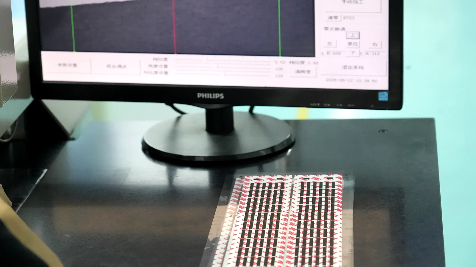
JASPER certifications: ISO 9001, ISO 13485, IATF 16949, and ISO 14001.
This guide addresses a physical graphic overlay, not a Figma or Sketch screen overlay. It is for engineers, quality teams, and sourcing teams approving custom graphic overlays for equipment panels. The decision boundary is narrow: does the inspected sample represent the intended construction, and does the recorded evidence close the risks assigned to that sample stage? A prototype by itself does not prove production repeatability, service life, enclosure ingress protection, or finished-device compliance. It also does not authorize a later material, process, or supplier change.
1. Why a Prototype Can Look Right and Still Be Unfit for Release
A graphic overlay is ready for release only when the evidence matches the decision being made. A clean print can still carry the wrong revision, use a substitute film, omit a blocking layer, place adhesive across a window, or fit only while it is lying loose on a bench. None of those defects is fixed by signing the front of the sample.
The practical remedy is to name three approval gates. JASPER's public production-intent prototyping framework likewise separates artwork/layout, functional, production-intent, and pilot evidence rather than treating every sample as interchangeable.
The distinction matters because production intent is a statement about representation, not a flattering label. An exact film callout includes grade, gauge, finish, and print treatment. MacDermid Alpha's own multiple Autotex PET, Autotex PC, and Autoflex gauges plus different primer, embossing, and window-treatment options. Covestro likewise separates Makrofol and Bayfol grades for general graphics, die cutting, chemical resistance, and forming. “Polyester” or “polycarbonate” therefore does not identify a production construction.
The failure chain to stop
Uncontrolled revision → wrong print, window, cut, emboss, or adhesive geometry → misleading prototype → installed defect or invalid test → production hold or rework.
The weak link is often evidence reuse. A digitally printed, laser-cut sample may be the best choice for checking icon hierarchy, basic layout, and early enclosure clearance. It is not the best release sample when production will change the film grade, ink and cure route, color build, die tooling, emboss tooling, adhesive, liner, or application process. In that situation, the release decision belongs to a production-intent first article or pilot that contains those features, not to the rapid sample.
2. The 10-Point Graphic Overlay Prototype Checklist
The graphic overlay prototype checklist below turns “looks acceptable” into ten controlled decisions. For each one, record the requirement source, sample condition, method, evidence, acceptance owner, and disposition. JASPER's public guidance for project-specific testing uses the same core fields because a result has little release value when its specimen stage or acceptance authority is unknown.
| Approval item | Inspect in this condition | Acceptance source | Evidence to retain |
|---|---|---|---|
| Sample purpose | Identified artwork, appearance, fit, functional, or production-intent stage | Prototype plan / purchase requirement | Gate and question list |
| Artwork | Controlled drawing plus active production artwork | Drawing, artwork brief, language/symbol register | Disposed proof with exact revisions |
| Build representation | As-built film, print, adhesive, liner, conversion, and tooling route | Released or proposed construction | Representativeness and substitution table |
| Color and opacity | Selected film/finish; defined reflective, transmissive, lit, and unlit states | Physical master and/or agreed instrument method | Comparison record and retained master |
| Windows | Loose overlay and installed, powered display/indicator | Optical specification and assembly drawing | Haze/transmittance data if required; installed photos/observations |
| Emboss and cut geometry | Relaxed part at defined conditioning plus installed panel | Dimensioned drawing and datum scheme | Inspection report and marked drawing |
| Adhesive and liner | Actual housing or controlled equivalent after defined application and dwell | Adhesive specification and installation instruction | Build ID, substrate, preparation, dwell, and test result |
| Assembly fit | Intended recess, bezel, display, support, and application process | Housing CAD/drawing and assembly instruction | Fit disposition and defect map |
| Use-risk tests | Construction and assembly state named in the test plan | Customer requirement and scoped standard/method | Pre/post data, condition log, photos, disposition |
| Revision and release | Exact inspected configuration | Document-control procedure and authorized deviations | Signed approval record, retained reference, re-sample triggers |
2.1 Name the sample's purpose and acceptance owner
Start with the decision, not the part. An artwork-layout sample can confirm label hierarchy and window position; an appearance sample can confirm a physical finish; a fit sample can close enclosure geometry; a production-intent sample can represent proposed materials and processes. Combining those names without defining the represented features invites evidence drift.
The approval header should identify the sample stage, questions to close, characteristics to inspect, condition and method for each check, required evidence, and the person or function authorized to accept it. “For review” is not a disposition. Use approve, conditional approve, or reject, and attach every condition to an owner and due date.
The cover sheet says, for example, “Production-intent appearance and fit sample; optical and environmental qualification remain open,” then names the drawing, assembly, reviewer, and required outputs.
The bag or email says “final sample” but does not identify what is final, who can release it, or which questions remain outside scope.
2.2 Approve the overlay artwork proof against controlled product definition
An overlay artwork proof should settle meaning before anyone judges ink. Compare it with the dimensioned drawing, not with memory: part number, drawing revision, artwork revision, language, legends, warning text, icons, color IDs, opacity zones, clear and tinted windows, dead-front graphics, backlighting masks, cut paths, emboss areas, adhesive keep-outs, and orientation marks.
ASME Y14.5-2018 (R2024) establishes a common language for stating and interpreting dimensional requirements on drawings and related documents. It does not provide a generic overlay tolerance; the product drawing must do that work. Likewise, ISO 12647-7:2016 covers hard-copy digital proofs intended to simulate a defined printing condition. An ordinary PDF, monitor preview, or office print can approve content and separation intent, but it is not automatically a contract color proof.
A disposed proof carries the exact drawing and artwork revisions, date, approver, and marked exceptions. Manufacturing layers are visibly distinct and reconcile to the same datum/origin.
Approval exists only as “artwork OK” in an email thread, with no attached revision or record of which window, emboss, cut, and adhesive layers were reviewed.
2.3 Record what the prototype represents—and what it substitutes
“Production-intent” is credible only when an as-built record names the construction. At minimum, record film manufacturer, grade, gauge, finish and treatment; print side, ink/process and blocking layers; adhesive product/family, nominal thickness, pattern and liner; cut method; emboss tooling and profile; and the mounting substrate or controlled equivalent.
| Construction element | Production-intent evidence | If the prototype differs |
|---|---|---|
| Film and surface | Exact grade, gauge, finish, primer/hardcoat, lot or traceable batch | Name the substitute and block durability, optical, emboss, or chemical conclusions it cannot support |
| Print stack | Process, ink system, print order, white/blocking layers, cure route | Limit approval to content/layout or require a production-print sample for color/opacity release |
| Windows and masks | Clear/tinted film, bezel mask, dead-front layers, surface treatment | Retest optical and lit/unlit behavior on the intended stack |
| Conversion | Production die/laser route, datum, cut and emboss tooling | Treat hand-cut or temporary-tool results as geometry clues, not final edge/tooling evidence |
| Adhesive and liner | Exact family/product, coat thickness, pattern, liner, lamination route | Reopen bond, application, handling, and thickness/fit approval |
| Mating assembly | Intended housing finish, bezel, display, switch/support stack | Document coupon equivalence or repeat the installed test on the real assembly |
This record prevents a grade-level change from hiding behind a polymer name. Primary film catalogs from MacDermid Alpha and Covestro show multiple PET, PC, Makrofol, and Bayfol grades with different gauges and converting treatments. The catalogs prove variation within a family; they do not rank all PET against all PC.
The related graphic overlay materials resource is the planned route for grade-level film and adhesive construction guidance. Use it to narrow candidates, then keep the exact selected grade, gauge, finish, treatment, and adhesive in the prototype record.
Every difference is listed with its affected characteristic, temporary rationale, and closure gate.
The sample is called production-intent because its outline matches, even though film, ink route, emboss tooling, or adhesive will change.
2.4 Approve color and opacity under defined viewing and measurement conditions
Color approval needs a reference and a method. Identify the physical master or coded reference, film and finish, print order, background, measurement location, instrument condition, illuminant/observer, color-difference formula, viewing environment, and agreed limit. ASTM D2244-25 explicitly leaves permissible color tolerance and the calculation procedure to purchaser-seller agreement; Gloss and texture can change commercial acceptance. ISO 13655:2017 covers spectral measurement and colorimetric computation for graphic arts, while ISO/CIE 11664-4:2019 defines CIE L*a*b* coordinates. None supplies one universal ΔE limit for overlays.
Visual review also needs discipline. ISO 3664:2025 covers critical viewing of reflective and transmissive media, including backlit signs. For opacity, masks, and dead-front icons, inspect the part under the intended light source in both lit and unlit states; JASPER's graphic overlay printing controls treat those states separately.
The record pairs instrument data, when required, with a controlled visual comparison on the selected film/finish and installed lighting.
A monitor screenshot or Pantone callout is treated as proof of the final printed, textured, backlit construction.
2.5 Approve display and indicator windows as optical zones
A window is not just an unprinted rectangle. Define the active display or indicator, clear opening, printed bezel/mask, adhesive keep-out, film or insert, tint, surface treatment, housing bezel, viewing direction, and cosmetic zone. Inspect dust, scratches, distortion, clipped active area, print registration, mask leakage, adhesive intrusion, and surface damage before and after assembly.
ASTM D1003-21 provides methods for haze and luminous transmittance of essentially transparent planar plastics. Those values can control a nominated window construction, but they do not guarantee readability. The powered assembly must still be reviewed at the intended brightness, ambient light, distance, and viewing angles. JASPER's related graphic overlay with a display window page documents this as a representative engineering process, not as a named-customer performance result.
The window record includes a marked optical-zone drawing, specified method or physical master, lit/unlit observations, and installed photos from required viewing directions.
The drawing says only “clear window,” or approval is performed on a loose film over a phone screen under convenient office lighting.
2.6 Inspect embossing, cut geometry, and registration from functional datums
Overall length and width cannot prove that a window clears the display, a hole finds a fastener, or an embossed key aligns with an actuator. The drawing should control feature position and profile from functional datums tied to the housing and underlying controls. Record the required cutout, window, emboss, key, border, and edge dimensions; measurement method; conditioning/relaxation state; fixture; and permissible visual defects.
Check the loose part for profile, cut quality, burrs or hanging waste, print-to-cut registration, emboss shape and damage. Then install it. A dimensionally compliant flat film can still wrinkle in a recess, bridge a step, expose the bezel, clip a display, or preload a switch when adhesive thickness and stack-up are introduced.
The related guide to emboss geometry and first-off approval expands the drawing and inspection questions for rim, dome, pillow, and key emboss features.
A marked inspection drawing shows which datum and method control every critical feature, and the installed fit closes the relevant tolerance stack.
The sample passes because a ruler confirms the outside size, while window, emboss, hole, and edge relationships remain unmeasured.
2.7 Validate the adhesive, pattern, liner, and application process together
Adhesive approval starts with the housing: resin or metal, paint or powder coat, texture, curvature, flatness, cleanliness, expected contamination, cleaners, temperature, moisture, edge loading, and service stress. Then identify adhesive family/product, nominal coat thickness, pattern and keep-outs, release liner, lamination route, surface preparation, application temperature and pressure, dwell, test temperature, peel geometry, and rate.
3M's 300LSE product guidance identifies the family for low-surface-energy substrates. Product choice still depends on the real surface and use conditions; the named family is an example, not a declaration that JASPER uses it on a given overlay.
Dwell is measurable, not ceremonial. In one product-specific example, the 90° ASTM D3330 peel at 23°C with 2 mil aluminum-foil backing and a 304 mm/min rate. Typical adhesion rises from 8.8 to 12.4 N/cm on ABS and from 9.7 to 11.3 N/cm on polypropylene between 15 minutes and 72 hours. 3M labels the data representative or typical and not for specification; these values are not JASPER specifications or acceptance limits.
The team applies the production-intent adhesive to the actual enclosure or a documented equivalent, uses the intended liner-removal/application method, waits the specified dwell, and records edge lift, bubbles, repositioning damage, and agreed bond evidence.
A hand-applied corner peel immediately after lamination is treated as lifetime bond approval.
2.8 Check the control panel overlay prototype in the intended assembly
Installed review closes interactions that a loose sample cannot expose. Use the intended housing recess, bezel, display or indicators, switch/actuator or support surface, fasteners, gasket where applicable, and assembly sequence. Verify edge coverage, gap and flushness, label and control alignment, window clipping, emboss-to-actuator position, adhesive squeeze or keep-out, liner removal access, application alignment, bubbles, wrinkles, local bridging, and service access.
Power the display or indicators when the overlay includes clear, tinted, masked, or dead-front regions. Operate the controls when embossing and underlying actuation interact. If a controlled equivalent replaces the housing, document its material, coating, texture, curvature, flatness, and why the team accepts it as equivalent.
Loose, bonded, powered, and operated states have separate observations, with photographs or marked defect maps tied to the same sample ID.
Fit approval consists of placing an unbonded overlay on a printed housing drawing or a different surface finish.
2.9 Use a condition-based test matrix, not a standards shopping list
Select tests from documented exposure and failure risk. A standard number without specimen construction, severity, duration, sequence, preconditioning, measurement, and acceptance criterion is not a test plan.
| Risk to close | Specimen/configuration to name | Possible primary method | Acceptance field that must remain project-specific |
|---|---|---|---|
| Temperature-change stress, registration shift, edge lift | Loose overlay, bonded coupon, or complete panel; actual material stack | IEC 60068-2-14:2023 | Temperature profile, dwell/transfer, cycles, recovery, dimensional/cosmetic/bond limit |
| Steady high humidity without condensation | Bonded construction or equipment configuration | IEC 60068-2-78:2025 | Severity, duration, recovery, haze/color/edge-lift/function limit |
| UV, heat, and moisture weathering | Selected film/ink/coating construction with controls | ASTM G154-23 | Lamp/cycle/conditions, duration, comparator, post-exposure property and limit |
| Cleaner or chemical contact | Finished print/film/edge/adhesive configuration; actual chemistry | Customer method or applicable material method | Chemical identity/concentration, wipe or soak method, cycles, recovery, visual/functional limit |
| Abrasion or coating hardness | Selected surface film/hardcoat on an applicable support | Material-supplier method; ASTM D3363-22 only when applicable | Tool, load, cycles or pencil lot, substrate, defect definition, limit |
| Ingress at the panel | Complete evaluated enclosure and seal path | IEC 60529 when contractually required | Full configuration, exposure direction, IP test, post-test criteria, responsible approving body |
ASTM G154 is especially easy to misuse: it governs operation of fluorescent UV equipment and requires reported exposure conditions; it does not convert a generic number of chamber hours into field years. IEC 60529 classifies protection provided by enclosures, so a loose overlay cannot earn an IP rating by itself.
Every row names the risk, specimen state, method and severity, pre/post measurements, limit source, evidence artifact, and acceptance owner.
The report says “UV tested,” “chemical resistant,” or “IP67 material” without a traceable configuration and result.
2.10 Close revisions, deviations, retained references, and re-sample triggers
Graphic overlay sample approval should release a configuration, not a photograph. Record part number, drawing and artwork revisions, sample ID/date, as-built materials and processes, deviations, test/inspection references, disposition, authorized approvers, retained physical master location, and the files that supersede earlier versions.
ASME Y14.35-2025 covers revision practices for engineering drawings and associated documents. ISO 10007:2017 provides configuration-management guidance across the lifecycle. Neither dictates one overlay form, but both support an unambiguous revision trail.
| Release-record field | Minimum content |
|---|---|
| Identity | Part number, drawing revision, artwork revision, sample ID, build date |
| As-built configuration | Film/finish, print stack, windows, cut/emboss route, adhesive/pattern/liner, mating surface |
| Evidence | Inspection and test references, specimen state, conditions, results, retained photographs/data |
| Disposition | Approve, conditional approve, or reject; exceptions, owner, due date, authorized approvers |
| Reference and change | Retained master/location, released files, superseded files, re-sample and targeted re-test triggers |
Define targeted re-sample triggers: film/finish or hardcoat; ink/process, color or opacity build; window/tint/mask; cut or emboss geometry/tooling; adhesive/liner/pattern; housing material/finish; assembly method; or any corrected artwork that affects meaning or registration. A spelling correction outside a controlled feature may need document review only; a moved window or changed adhesive invalidates the evidence that depended on it.
If a contract invokes AIAG PPAP or SAE AS9102C, integrate the overlay evidence into that customer program. A signed loose sample is not a substitute for automotive production approval or aerospace first-article documentation.
The disposition states what is approved, what remains conditional, which revision becomes active, and which future changes require document review, targeted re-test, or a new sample.
The team keeps an unlabeled “golden sample” while production files continue to change.
3. Run the Approval in Six Steps
The ten criteria become manageable when the team closes them in sequence. Each step ends with a record or a deliberate open item; silence is not approval.
Step 1 — Freeze the evidence hierarchy
List the governing purchase requirement, drawing, artwork, material/construction specification, assembly drawing, test plan, and physical master. State which document wins if two disagree. Open an issue register with owner, due date, affected gate, and stop/release consequence. Do this before manufacturing interprets missing data.
Step 2 — Approve artwork meaning before physical color
Dispose the overlay artwork proof against the drawing. Close text, language, icons, warnings, feature layers, window and opacity intent, cuts, embossing, adhesive keep-outs, orientation, and revisions. A content proof may proceed while physical color remains open, but the record must not merge the two decisions.
Step 3 — Authorize the sample build
Issue an as-planned construction sheet naming film, print stack, windows, conversion, emboss tooling, adhesive, liner, and mating surface. Mark every temporary material or process. For each substitution, state which conclusions remain valid and which require another production-intent sample.
Step 4 — Inspect the loose part
Verify identity first, then appearance and geometry. Check revision marks, color/opacity state, surface, contamination, windows, print-to-cut registration, cut edges, holes, embossing, outside profile, adhesive pattern, liner condition, and handling damage. Record actual values where the drawing gives a measurable limit; do not replace them with “pass” alone.
Step 5 — Install, power, operate, and condition
Apply the overlay with the intended preparation, pressure, alignment method, and dwell. Inspect the real enclosure fit, edges, recess, windows, indicators, emboss-to-control alignment, bubbles, wrinkles, and liner/application behavior. Power optical features and operate affected controls. Run only the risk-based exposures defined in the approval matrix.
Step 6 — Disposition and release the configuration
Choose approve, conditional approve, or reject. Close or assign every deviation, identify the active revisions and retained reference, then state which changes require document review, targeted testing, or a new sample. Production receives the released files and acceptance record—not an unlabeled sample passed from desk to desk.
4. Engineering Approval Starting Points
Source-backed starting values
A prototype request often stalls when every acceptance field says “not yet defined.” That is a planning failure. The values below make the discussion concrete by selecting a representative mid-to-upper-control point from an established material supplier or print-control source. They are project-specific inputs, not industry-wide standards. A released drawing or agreed test plan must replace each value after the exact film, finish, print process, adhesive, substrate, and use condition are known.
| Approval field | project-specific planning value | Source and condition | Required replacement before sample approval |
|---|---|---|---|
| Film construction | 250 µm nominal hardcoated polyester; supplier thickness tolerance nominal ±10% | MacDermid Alpha Autoflex EB TDS. The sheet lists 250 µm as one available Autoflex EB gauge, not an industry-standard overlay thickness. | Exact manufacturer, grade, gauge/tolerance, Gloss or Antiglare finish, primer/hardcoat, print side, and released drawing/BOM reference |
| Clear Gloss window | Total luminous transmission 91% ± 2%; haze <2% | Same Autoflex EB TDS, ASTM D1003 typical data. The <2% haze figure is for Gloss; 250 µm Antiglare is reported separately at 10.8% ± 3%. | Exact optical-zone construction, specimen thickness/finish, ASTM D1003 procedure, sampling, instrument, limit, and installed powered-display acceptance |
| Surface hardness | 2–3H pencil hardness | Same Autoflex EB TDS under supplier method 058. This must not be relabeled as an ASTM D3363 result. | Exact film/hardcoat, applicable test method, support, pencil lot/conditioning, defect definition, sampling, and pass limit—or delete if hardness does not close a project risk |
| Nominated spot colors | ΔE00 ≤2.0 against the approved physical master | typical graphic-arts customer tolerances as 2–6 generic ΔE units; its separate against converting between equations. The chosen ΔE00 value is a buyer-selected high-stringency planning target, not a universal overlay or printing standard. | Formula, reference, instrument and geometry, calibration, illuminant/observer, substrate/finish, backing, locations, sampling, single-color maximum or average rule, and visual override |
| Adhesive screening on nominated ABS or PP | ≥11.0 N/cm after 72 hours as a project-specific buyer-selected comparison point—not a statistical or universal pass limit | The 3M 9453LE TDS reports typical 90° ASTM D3330 values at 23°C, 304 mm/min, and 2 mil aluminum backing: 12.4 N/cm on ABS and 11.3 N/cm on PP after 72 hours. | Actual adhesive, coat thickness, liner, nominated ABS/PP grade and finish, preparation, application pressure/temperature, dwell, backing, peel geometry/rate, sampling, aging, failure mode, and project-owned acceptance limit |
Scope is everything. These values are not the best choice when the production overlay uses another finish, gauge, ink route, adhesive, liner, or substrate. In that case, carrying the benchmark into release would create false precision. Replace it with production-intent data or leave the characteristic open and assign a test owner.
Management-system certificates and UL component recognition answer supplier-qualification questions; they do not approve a particular graphic overlay prototype. The released construction and production-intent validation remain controlling.
5. Release Blockers That Stop Graphic Overlay Sample Approval
These conditions override a good-looking sample because they make the evidence untraceable or assign it more scope than it earned.
- Drawing and artwork revisions conflict or are missing. The inspected configuration cannot be reconstructed.
- “Production-intent” has no as-built record. Material, print, tooling, adhesive, and liner substitutions remain invisible.
- Color is approved from an uncontrolled display. Physical film, finish, print order, and viewing conditions are absent.
- Windows are reviewed without the intended display or light source. Clipping, haze, tint, mask leakage, and readability remain open.
- Adhesive is tested without the housing surface and application record. Surface energy, texture, contamination, pressure, and dwell are unknown.
- Fit is checked only on a loose flat part. Recess, bezel, stack-up, edge, and application defects can escape.
- A standard is named without specimen, condition, method, and limit. “Tested to” has no reproducible meaning.
- Approval is verbal or conditional items have no owner. Production can start against a moving target.
6. Frequently Asked Questions
Is an overlay artwork proof the same as a physical prototype?
No. An overlay artwork proof approves content, layers, geometry intent, and revision identity. A physical prototype adds evidence about film, printing, finish, opacity, windows, embossing, cut geometry, adhesive, liner, and fit—but only for the construction it actually represents.
What makes a graphic overlay prototype production-intent?
Its as-built record matches the proposed production film, finish, print stack, conversion and emboss tooling, adhesive, liner, and assembly surface, or identifies each substitution and its limitation. The label “production-intent” is not enough.
What should be sent with a control panel overlay prototype request?
Send the dimensioned drawing and available enclosure data, active artwork, window and indicator definitions, material and finish preferences, housing substrate and texture, adhesive/application information, operating exposures, expected assembly, sample purpose, and acceptance questions.
How should color and opacity be approved?
Use the selected film and finish, a named physical or coded reference, defined measurement and viewing conditions, and a purchaser-approved tolerance. Review opacity, masks, and dead-front graphics in both lit and unlit states with the intended light source.
What should a display-window check include?
Check the active display, clear opening, printed mask, adhesive keep-out, tint, surface, registration, scratches, contamination, and housing bezel. Measure haze or transmittance if specified, then review the powered assembly at required ambient light and viewing angles.
How should overlay adhesive be approved?
Identify the actual housing material or coating, texture, cleanliness, surface preparation, adhesive and thickness, pattern, liner, application temperature and pressure, dwell, test condition, and acceptance method. Test the real surface or document why a coupon is equivalent.
Does a control panel overlay prototype prove an IP rating?
No. IEC 60529 classifies protection provided by an evaluated enclosure. Panel edges, adhesive land, windows, gaskets, tail or cable paths, joints, assembly pressure, and exposure direction can change the result; a loose overlay cannot establish it.
Which changes require another graphic overlay sample?
Re-sample when a change invalidates prior evidence: film/finish, print process, color or opacity build, window/tint/mask, cut or emboss geometry/tooling, adhesive/liner/pattern, housing surface, assembly method, or artwork that moves or changes a controlled feature.
Can one graphic overlay prototype checklist fit every project?
The evidence fields can be reused, but the methods and limits cannot. Each project sets its own critical characteristics, specimen configuration, viewing and measurement conditions, exposure severities, acceptance limits, approving functions, and finished-device validation boundary.
What belongs in the signed graphic overlay sample approval record?
Record part number; drawing and artwork revisions; sample ID and date; as-built materials and processes; inspections and tests; deviations; approve, conditional-approve, or reject disposition; approvers; retained reference; released files; open items; and re-sample triggers.
7. Prepare a Production-Intent Prototype Package
The next useful action is not a vague request for “a sample.” Assemble the current drawing and artwork, enclosure and display context, construction proposal, representativeness table, approval matrix, open-item register, and disposition sheet. Mark unknowns rather than filling them with assumed values. Then ask the converter to confirm which sample can close artwork, appearance, fit, optical, adhesive, and production-release questions—and which evidence still belongs to the finished assembly.
When the file set is ready, submit the production-intent prototype package with the required evidence fields rather than a bare price request. Other qualified converters may use different form names; the decisive point is that each claim remains tied to the represented construction, defined condition, active revision, and authorized owner.
Prepare a production-intent prototype package before releasing tooling or repeat production.
Technical References
- Source: Makrofol and Bayfol grades. Accessed 2026.
- Source: ASME Y14.5-2018 (R2024). Accessed 2026.
- Source: ISO 12647-7:2016. Accessed 2026.
- Source: MacDermid Alpha. Accessed 2026.
- Source: Covestro. Accessed 2026.
- Source: ASTM D2244-25. Accessed 2026.
- Source: ISO 13655:2017. Accessed 2026.
- Source: ISO/CIE 11664-4:2019. Accessed 2026.
- Source: ISO 3664:2025. Accessed 2026.
- Source: ASTM D1003-21. Accessed 2026.
- Source: 300LSE product guidance. Accessed 2026.
- Source: IEC 60068-2-14:2023. Accessed 2026.
- Source: IEC 60068-2-78:2025. Accessed 2026.
- Source: ASTM G154-23. Accessed 2026.
- Source: ASTM D3363-22. Accessed 2026.
- Source: IEC 60529. Accessed 2026.
- Source: ASME Y14.35-2025. Accessed 2026.
- Source: ISO 10007:2017. Accessed 2026.
- Source: AIAG PPAP. Accessed 2026.
- Source: SAE AS9102C. Accessed 2026.
- Source: MacDermid Alpha Autoflex EB TDS. Accessed 2026.
Review the finished overlay construction before release
Send the drawing, artwork, substrate, adhesive, assembly, environment, optical states, and acceptance evidence for a construction-specific review.