
Flexible pressure sensor array design determines where a seat mat senses load, how each zone reaches the connector, and what the electronics can reliably decide. For seat-system engineers and sourcing teams, the key question is not how many zones will fit. It is what each zone must decide under the real foam, trim, occupant, cargo, temperature, and aging conditions. A sound design develops zone geometry, circuit topology, lamination, readout, calibration, and validation together. The boundary matters: a flexible seat pressure sensor is one component. By itself, it cannot establish occupant-classification accuracy, FMVSS No. 208 conformity, or ISO 26262 compliance for the completed vehicle system.
1. Why a multi-zone seat-sensor decision goes wrong
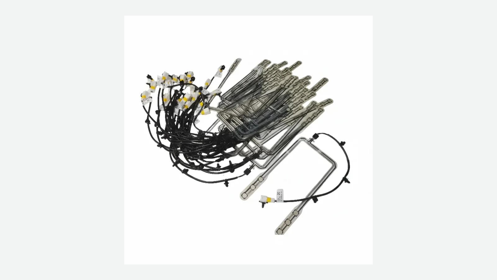
A flexible pressure sensor array is a set of pressure-responsive areas on a bendable carrier, with conductors that bring the zone signals to a tail or local readout circuit. Unlike a single switch, the array preserves some location information. Unlike a calibrated pressure-mapping instrument, a low-channel-count seat mat may only need to report a few analog values or state changes.
That middle ground is useful, but easy to mis-specify. A team may draw twelve equal zones before defining the decision, route every conductor through the highest-strain area, or calibrate a flat sensor and expect the same response after foam and trim redistribute the load. The result can be false activation, missed edge loading, channel interaction, unstable zero values, or a tail that fails before the sensing layer does.
The design must begin with a program-level observation contract: which physical condition enters the seat, which raw signals leave the mat, and which ECU or controller owns the classification decision. The linked flexible membrane seat pressure sensor project page treats sensing principle, stack, tail, connector, and validation plan as project-specific inputs rather than fixed catalog claims.
The same component boundary belongs in the wider automotive sensor integration path: the mat supplies an electrical input, while the seat, controller, diagnostics, restraint logic, and vehicle validation determine the system result.
For United States vehicle programs, the official 49 CFR § 571.208 defines occupant-crash-protection requirements and includes provisions for suppression and occupant-sensing systems. ISO 26262-1:2018 applies a functional-safety framework to safety-related electrical/electronic systems. Neither source turns a pressure mat into a compliant system by itself. The vehicle or system owner still controls hazards, diagnostics, classification logic, integration, and validation.
2. Start with the sensing stack and channel architecture
A printed sensor array should be described as a controlled stack, not a silhouette with colored zones. One common resistive construction uses two flexible membranes separated by a spacer-controlled air gap. Interdigitated conductors sit on one membrane; a force-responsive layer sits on the other. Applied load changes the electrical path. The Interlink Electronics FSR Integration Guide documents that architecture and identifies PET, polyimide, printed silver conductors, carbon-based sensing ink, and pressure-sensitive spacer adhesive as examples—not universal requirements.
Representative stack, top to bottom
Seat trim / foam load path ← part of the calibration fixture
Protective or mounting interface ← project-specific, may be outside the sensor
Upper flexible carrier
Force-responsive material or contact pattern ← architecture-specific
Spacer / adhesive openings / optional vent
Printed conductor layer and zone traces
Lower flexible carrier
Rear adhesive or mechanical retention
Tail conductors → stiffener → connector ← enters the customer electronics
This diagram is a functional model. A contact-switch mat, a shunt-mode resistive sensor, a through-mode piezoresistive stack, and a capacitive array do not share the same layer order. Calling all four “membrane sensors” does not make their electronics interchangeable.
Architecture decision table
| Architecture | Best fit | Tail / channel consequence | Main error mechanism | Decision boundary |
|---|---|---|---|---|
| Direct-wired independent zones | A small number of binary or analog regions with strong diagnostic separation | Each zone keeps a dedicated measurement path or return strategy | More conductors, larger tail, more connector pins | Prefer when isolation and fault localization matter more than conductor count |
| Passive row-column matrix | Many intersections must be addressed with fewer conductors | An M × N field can use M + N row/column lines | Bypass currents, unselected-pixel influence, multiplexer resistance, and mechanical coupling | Use only with a readout method proven across the expected resistance and simultaneous-load states |
| Individually switched nodes | Moderate channel count with electronic isolation | Each node receives a switch and measurement path; local hardware grows with channel count | Switch leakage, settling, component tolerance, and harness complexity | Useful when channel isolation is worth more electronics |
| Calibrated pressure-mapping system | Engineering measurement or continuous pressure images rather than a few seat states | Dense sensor field plus dedicated acquisition hardware and software | Calibration drift, spatial interpolation, scan timing, and installation effects | Choose when the output must be a pressure map, not merely occupancy features |
Original research demonstrates the trade. A shared row-column resistive array saves wiring but creates bypass-current paths that depend on unselected elements, switch resistance, and array size; an improved zero-potential circuit was developed specifically to reduce that error (Wu et al., 2016). Another study independently switched each node and gave it a divider path to avoid channel crosstalk (Zhang et al., 2022). A seat-scale printed research array used crisscross conductors to reduce lead count, but its dimensions and performance belong to that prototype, not to every flexible sensor (Zhu et al., 2023).
3. A 10-point flexible pressure sensor array design framework
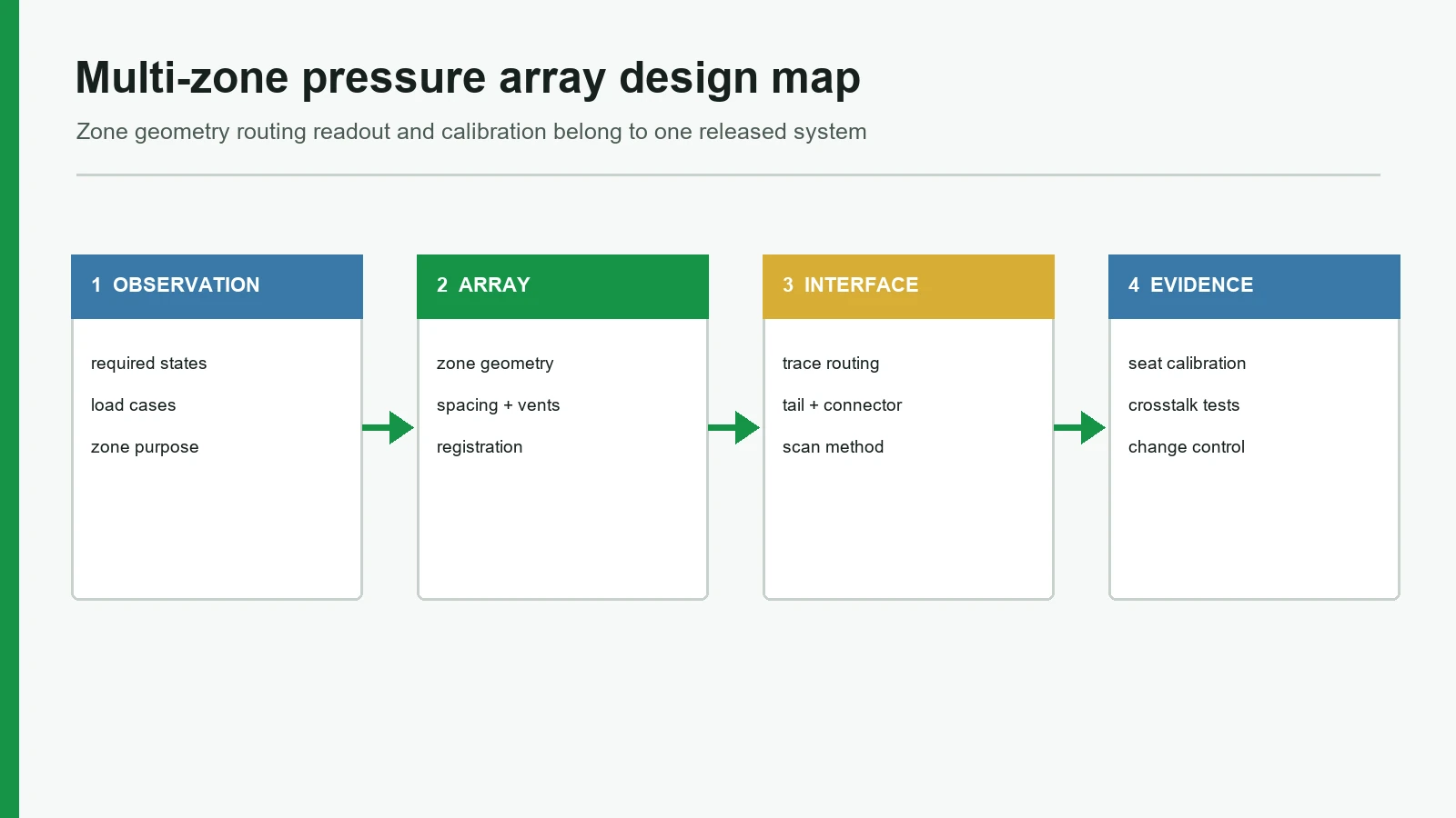
The framework below turns the application into ten reviewable decisions. It covers the observation contract, zone geometry, topology, printed routing, spacer and adhesive, tail, crosstalk, readout, calibration, and controlled validation. A supplier should be able to point to the drawing, test, or interface document that closes each item.
3.1 Define the decision before the zone count
Start with the output contract. A zone may need to report open/closed state, resistance, voltage, relative load, or a calibrated pressure estimate. Those are different products. The system requirements should also state whether simultaneous loads matter, whether a bag or child restraint is an intended challenge case, how quickly a state may change, and what happens when a channel is open, shorted, stuck, or implausible.
a truth table connects physical cases, raw channel behavior, derived features, system state, response timing, and fault handling.
the request specifies “8 zones” or “12 zones” without stating what those zones must distinguish.
3.2 Derive zone geometry from the assembled load path
Equal rectangles are convenient to draw, not necessarily useful to sense. Foam thickness, trim seams, heating elements, ventilation passages, suspension structures, and occupant posture can move or spread load before it reaches the sensor. Force distribution, actuator shape, placement, material, and loading rate can materially change a resistive sensor response. Match evaluation conditions to final use conditions (Interlink Electronics, pp. 26–27).
Zone boundaries should therefore follow decision-sensitive load paths. Include boundary presses, off-center postures, cargo, kneeling, entry/exit transients, and unloaded trim preload in the layout study.
The pressure sensor mat design envelope provides the broader application path. For a seat program, however, the released zone geometry still has to come from the actual seat stack and labeled load cases.
the drawing overlays candidate zones on seat datums, foam features, trim seams, and defined load-case locations.
a flat-bench heat map is the only evidence for an installed geometry.
3.3 Select topology with simultaneous-load cases present
A topology that reads one pressed point correctly may still fail when several points conduct at once. Direct-wired zones simplify fault isolation but expand the tail. A shared matrix saves conductors but moves complexity into selection, biasing, and error correction. The topology review must use the highest and lowest expected channel impedances, every required simultaneous-load pattern, open/short faults, and connector/contact resistance.
a circuit model and prototype test compare selected and unselected channels across the full simultaneous-load set.
conductor savings are approved from the pin count alone, before a crosstalk budget exists.
3.4 Route printed conductors as both electrical and mechanical features
Trace width, spacing, length, crossings, insulation, and registration belong on the controlled drawing. A supplier's printable minimum is only a process capability; the design value needs margin for sheet registration, ink geometry, conductor resistance, lamination movement, and the strain created by installation. Keep routing corridors away from pressure-critical boundaries where practical, and show every crossover or dielectric bridge explicitly.
IPC-2292A (October 2022) covers design principles for printed electronics on flexible, non-stretchable substrates, including layout, materials, testability, tails, and connectors. IPC-2292A is not a performance specification or acceptance document, so it does not supply one universal line width or spacing for every ink, film, printer, and vehicle program. A related membrane circuit design guide can serve as an internal drawing reference without replacing project-specific limits.
3.5 Control the spacer, adhesive, sensing layer, and vent as one system
Spacer openings set where layers can interact. Adhesive lands hold registration and also change local stiffness. A vented air-gap design needs a controlled path to equalize pressure; a sealed construction has a different stack and failure model. These choices cannot be reviewed independently.
Air bubbles, contamination, kinks, blocked vents, and excessive shear can change response or damage a vented FSR construction (Interlink Electronics, p. 30). That warning should become inspection features: adhesive coverage, vent continuity where applicable, trapped-particle criteria, layer registration, and a flatness or preload check after lamination.
a layer table identifies material revision, thickness or coating callout, adhesive land, vent path, zone opening, registration tolerance, and controlled substitute policy.
the bill of materials names “PET + adhesive” but omits coating, cure, spacer geometry, venting, and approved equivalents.
3.6 Design the tail before freezing the sensing field
The tail is a flexing interconnect, connector interface, handling tab, and possible leak path. Define its exit direction from seat kinematics, not from vacant drawing space. Specify the static and moving bend regions, keep-out around the active area, conductor fan-out, pin numbering, stiffener, insertion direction, retention, strain relief, and connector datum.
Kinks or creases can break printed silver traces, and bending near the active area can create preload and false readings. Do not solder directly to exposed silver on flexible film (Interlink Electronics, p. 30). Its example bend radii are product-specific, so the drawing should use a value supported by the selected stack and flex test—not copied from a generic guide.
a 1:1 route check demonstrates nominal tail clearance through the full seat motion, and a tail coupon verifies the released bend condition and connector process. Final clearance still requires physical samples and the released tolerance stack.
the tail is sharply folded at the zone edge or clamped by seat hardware without a defined bend and retention feature.
3.7 Separate four forms of crosstalk
“Crosstalk” is not one defect. The correction depends on where the unwanted signal enters.
| Error source | Failure chain | Isolation test | Typical design response |
|---|---|---|---|
| Mechanical | Load spreads through foam, trim, adhesive, or a continuous sensing layer → adjacent zone deforms | Press one zone while logging unloaded neighbors and boundary locations | Move boundaries, change support/spacer geometry, isolate pixels, or revise the mechanical stack |
| Passive-matrix electrical | Selected row/column creates unintended current paths through other conducting pixels → ghost value | Exercise worst-case simultaneous low-resistance pixels and open/short faults | Change topology, bias unselected lines, add isolation, or use a verified reconstruction method |
| Acquisition-chain | Multiplexer switches channels → source and input capacitance do not settle → previous channel contaminates the next | Alternate near-minimum and near-maximum signals while sweeping acquisition delay and channel order | Buffer, change impedance, extend acquisition time, discard an unsettled sample, or revise the ADC path |
| Interpretation | Baseline, normalization, threshold, or feature logic combines valid channels incorrectly → false state | Replay labeled raw data through every software revision | Lock channel map, units, baseline rules, threshold direction, timing, and versioned test vectors |
Li and colleagues showed that electrical isolation and mechanical decoupling both mattered in a high-resolution research array; its measured values remain specific to that laser-formed device (Advanced Materials, 2022). The practical lesson is the test split, not the study's pixel pitch.
the validation plan names the crosstalk type, excitation location, neighbor channels, calculation, and acceptance limit.
one “noise filter” is expected to cure foam load spreading, matrix ghosting, and ADC settling.
3.8 Co-design the readout with the printed sensor array
The readout specification needs more than ADC resolution. Record excitation method, current limits, divider or amplifier values, multiplexer state, source impedance, input leakage, acquisition time, sample timing, channel order, filtering, update rate, and fault-detection strategy. Then test them with the actual tail and connector.
Texas Instruments explains that an unbuffered multiplexed ADC has source-impedance and sampling-time constraints (SPNA061). Its multiplexer guidance also identifies on-resistance, leakage, output capacitance, source/load impedance, and settling as error terms (SCDA034). Analog Devices AN-1024 relates settling to switch timing and circuit resistance-capacitance. None of these sources prescribes a seat-mat scan rate. They show why the complete channel must be timed and measured.
the acquisition report includes a full-scale channel step, the final source impedance, measured settle time, sample point, channel sequence, and raw-versus-filtered data.
the nominal ADC samples-per-second value is treated as the sensor's validated update rate.
3.9 Calibrate the flexible seat pressure sensor in the assembled seat
First decide whether the output is force, pressure, resistance, voltage, or an uncalibrated feature. Pressure is force divided by area; the two quantities cannot be swapped without the contact area (NIST Guide to the SI). A seat mat that detects state may not need to report pascals at all.
Calibration should use the released foam, trim, adhesives, support, curvature, tail, electronics, load applicator, dwell time, and environmental state. Tekscan's 2024 electrical-integration guide similarly recommends calibrating each sensor in or near the final assembly with application-relevant loads and loading duration (Tekscan, Rev. C). An automotive OCS study also identified foam stiffness, cover material, preload, occupant and child-restraint cases, seat position, and temperature as program variables (SAE 2005-01-0461).
Signal interpretation flow: raw channel values → integrity checks → unloaded baseline → per-zone normalization or curve → time filtering → features such as zone sum, ratios, or center of pressure → state logic → diagnostic output. Every arrow needs units, version, and test vectors.
calibration retains raw data, fixture drawings, applied load and area, loading/unloading direction, dwell time, temperature, sample identity, curve revision, and residual error.
one flat-bench threshold is copied to every zone, seat variant, temperature, and production lot.
3.10 Make validation and change control part of the drawing package
A design is not released when the artwork looks correct. The release package needs electrical limits, dimensional characteristics, visual criteria, materials, calibration status, sample identity, test methods, test records, and revalidation triggers. Changes to ink, film, adhesive, cure, spacer, zone shape, tail, connector, foam, trim, electronics, or algorithm can alter the observation chain.
ISO 16750-3:2023, ISO 16750-4:2023, and ISO 16750-5:2023 categorize mechanical, climatic, and chemical loads for vehicle E/E equipment. The mounting location and vehicle program set the actual severities. IPC-9204 lists bend, torsion, rolling, crease, and folding principles for flexible printed electronics. Referencing a title is not evidence that a sample passed it.
a requirement-to-evidence matrix maps each released requirement to a method, sample condition, acceptance limit, record, owner, and change trigger.
a supplier declaration lists standards without test clauses, conditions, results, sample revision, or system boundary.
4. Run a six-step design and sample-approval process
A six-step design-and-approval process converts sensor requirements into controlled evidence. Skipping ahead usually hides a system decision inside sensor artwork.
Step 1 — Freeze the observation contract
Write the physical cases, required output, units, timing, simultaneous loads, fault states, and system owner. Separate a binary occupancy input from a relative load feature or calibrated pressure map. Record what the sensor does not decide.
Step 2 — Map the real seat stack
Collect the foam, trim, seam, heater, ventilation, support, fastening, and moving-hardware geometry. Instrument representative seats or use a mapping tool to locate stable load regions. Include edge posture, cargo, entry/exit, kneeling, child-restraint, temperature, unloaded-baseline cases, and trim-preload cases defined by the program.
Step 3 — Select topology and route the complete layout
Compare direct zones and shared addressing with all simultaneous-load states. Release a preliminary outline, active and inactive areas, spacer openings, traces, crossovers, tail, pin map, connector, datums, materials, and test pads. A production-intent prototyping review should check fit, circuit, stack, handling, and measurable outputs before tooling or production release.
Step 4 — Build instrumented prototypes
Measure every zone individually, at its edges, and while neighboring zones are loaded. Capture raw resistance or voltage, not only the controller state. Inspect registration, adhesive coverage, vents where used, tail strain, connector retention, and unloaded baseline after installation.
Step 5 — Calibrate and challenge the assembled seat
Use the released electronics and representative seat stack. Exercise loading and unloading, dwell, repeat placements, position changes, environmental conditions, cargo, and faults. Keep the raw channel log linked to fixture, seat, sensor, software, and calibration revisions. A public seat occupancy sensor mat case presents an anonymized manufacturing example, not proof of vehicle approval or classification performance.
Step 6 — Approve evidence, not a golden sample alone
The approval package should bind the sample to a revision-controlled drawing, bill of materials, electrical interface, calibration record, test matrix, acceptance results, deviations, and revalidation triggers. Changes then follow a documented engineering change-control path instead of an informal material substitution.
| Approval item | Minimum record |
|---|---|
| Design definition | Released outline, stack, zones, nets, tail, connector, datums, and controlled notes |
| Electrical behavior | Per-zone raw limits, open/short behavior, channel map, and acquisition conditions |
| Mechanical build | Registration, lamination, vent or seal condition, tail route, and retention evidence |
| Calibration | Fixture, load/area, dwell, environment, curve or threshold revision, and residuals |
| Validation | Requirement-to-test matrix, sample IDs, results, failures, corrections, and retest |
| Change control | Approved materials/processes, substitute policy, change owner, and revalidation trigger |
5. Validate the multi-zone pressure mat with a requirement-to-evidence matrix
A multi-zone pressure mat should be tested as a sensor, an installed seat component, and an input to electronics. Acceptance limits must come from the vehicle program; the matrix names the evidence needed and leaves each limit explicitly project-defined. The testing and validation planning page can support component-level planning, while finished-system verification remains with the responsible OEM or Tier team.
| Test block | Stimulus and condition | Record | Acceptance criterion / limit | Acceptance owner |
|---|---|---|---|---|
| Zone activation | Center and edge loads for every zone; loading, hold, and unloading | Raw curve, onset, saturation behavior, hysteresis, creep/drift, repeat placements | Project-defined output, repeatability, hysteresis, and hold-drift limits | Sensor / system engineering |
| Neighbor rejection | One zone loaded; adjacent and distant zones unloaded; boundary loads | Mechanical and electrical crosstalk by named calculation | Project-defined adjacent-zone and boundary-error limits | System engineering |
| Simultaneous load | Worst-case combinations for the selected topology | Selected/unselected channel error and ghost states | Project-defined selected-channel error; no prohibited ghost state | Electronics / algorithm owner |
| Zero and preload | Flat, curved, laminated, trimmed, and fully installed conditions | Baseline distribution, settling, false triggers | Project-defined baseline window and false-trigger rule | Seat / sensor engineering |
| Acquisition timing | Alternating low/high channels, final harness, full channel sequence | Settle waveform, sample point, update period, filtered latency | Project-defined settle error, update period, and latency | Electronics owner |
| Tail and connector | Released bend, insertion, retention, seat motion, and handling | Continuity, conductor resistance, intermittent events, visual damage | Drawing limits; no intermittent event or prohibited damage | Sensor / seat engineering |
| Mechanical environment | Program-selected vibration, shock, flex, and repeated loading | Before/during/after electrical behavior and physical inspection | Vehicle-profile electrical and physical change limits | Vehicle program |
| Climatic and chemical environment | Program-selected temperature, humidity, condensation, and agents | Baseline shift, zone response, adhesion, corrosion, recovery | Vehicle-profile shift, recovery, adhesion, and corrosion limits | Vehicle program |
| Assembled-seat cases | Defined occupants/surrogates, cargo, child restraints, positions, temperature | Raw signals, features, states, false-positive/negative cases | Program scenario coverage and state/error limits | System / safety owner |
| Fault response | Open, short, stuck, swapped channel, supply and connector faults | Diagnostic coverage, reaction, recovery, stored fault evidence | Safety-concept diagnostic coverage and reaction | Functional-safety owner |
The component report must identify sample revision and conditions. “Pass” without those fields is not reusable evidence.
6. Release blockers—and when a printed membrane array is not the best choice
The following findings should stop sample approval until the missing evidence is supplied:
- Zone count precedes the decision table. No physical case explains why each region exists.
- A uniform grid replaces seat evidence. Foam, trim, seams, support, and off-center loads were not evaluated.
- Topology was selected from connector pin count. Simultaneous-load and fault models are absent.
- The artwork has no netlist or stack control. Crossovers, spacer openings, vents, and material revisions are ambiguous.
- The tail was added after zone release. Bend area, retention, pin map, connector process, and seat-motion clearance are undefined.
- Only flat-bench calibration exists. Final foam, trim, curvature, electronics, dwell, and temperature are missing.
- One filter is claimed to remove all crosstalk. Mechanical spread, matrix paths, acquisition settling, and interpretation errors were not separated.
- Standards are listed without evidence. No clause, test condition, sample revision, result, or system boundary accompanies the claim.
A printed membrane array is also the wrong starting point in several legitimate cases:
| Requirement | Consider instead | Why |
|---|---|---|
| Only one total-load variable is required | Screen a single-force architecture before specifying an array | This is a requirements-simplification check: a zone map adds routing and calibration without adding a needed decision |
| A research-grade continuous pressure image is required | A calibrated pressure-mapping system such as novel pliance | The system includes dense sensing, acquisition, calibration, and analysis rather than only a custom mat |
| The surface repeatedly stretches over compound curvature | A conformable or stretchable textile/elastomer array such as TactArray | A bendable PET construction is not automatically stretchable |
| Local switching or amplification is required at every pixel | Evaluate an active-matrix architecture | Active pixels can remove passive-matrix current paths, but transistor on-resistance, circuit area, and readout design create new trade-offs (Lee, Yoo, and Kim, 2024) |
These are decision boundaries, not a universal technology ranking.
7. Project input checklist for a layout review
Send a supplier enough information to reproduce the observation chain:
- Seat package: 2D/3D outline, datums, foam and trim stack, seams, heaters/ventilation, support, mounting surface, motion envelope, and forbidden areas.
- Detection cases: required states, load or surrogate definition, placement, contact area, posture, cargo, child-restraint, transition, dwell, temperature, and fault cases.
- Electrical interface: output type and range, supply/excitation, input circuit, ADC, multiplexer, scan order, timing, connector, pinout, harness, grounding, and diagnostics.
- Sensor drawing inputs: candidate zones, active/inactive boundaries, topology, trace and spacing rules, crossovers, spacer, adhesive, vent/seal, tail, stiffener, labels, and test pads.
- Evidence plan: prototype stages, raw-data format, calibration method, acceptance limits, environmental matrix, sample quantity, records, revision control, and revalidation triggers.
- Supplier proof: exact legal manufacturing entity and site, certificate standard/number/issuer/scope/validity, public verification record, customer category, application scope, production phase, evidence artifact, and written permission to name any customer.
If any input is unknown, mark it as an open decision with an owner. Do not bury it in a supplier assumption.
8. Frequently asked questions
What is the first decision in flexible pressure sensor array design?
Define what the complete system must decide and what raw output the sensor must provide. State the physical cases, units, simultaneous loads, timing, faults, and system owner before choosing zone count, shape, topology, or materials. This prevents sensor artwork from silently becoming the system specification.
How many zones should a multi-zone pressure mat have?
Use the fewest zones that reliably separate the required cases in the assembled seat. More zones increase routing, connector, scan, calibration, and fault-handling work. A uniform count is not an industry standard; it must follow the seat load paths and the decision features.
Is a row-column matrix better than independent zones?
Neither is universally better. Independent zones use more conductors but simplify isolation and fault tracing. A row-column matrix reduces tail conductors but can introduce unintended current paths and readout errors. Compare both architectures under simultaneous loads, faults, and final electronics before release.
How can crosstalk be reduced in a printed sensor array?
First identify whether the error is mechanical, matrix-electrical, acquisition-chain, or interpretive. Then change the matching cause: zone support or isolation, bias/readout topology, multiplexer and ADC settling, or signal logic. Verify the fix by loading one zone while recording named neighbors and boundary cases.
Should a flexible seat pressure sensor be calibrated before or after assembly?
Bench characterization is useful, but final calibration should reproduce the assembled seat as closely as practical. Foam, trim, curvature, adhesive, preload, tail, electronics, load area, dwell, and temperature can alter the signal. Keep both loading and unloading data linked to the exact sample and fixture revision.
What should the tail drawing specify?
Specify the exit direction, moving and static bend regions, keep-outs, conductor fan-out, nominal and minimum geometry, pin numbering, pitch, contact finish, stiffener, insertion direction, connector, retention, strain relief, test access, and seat-motion clearance. Validate the released stack at the released bend condition.
Can a pressure sensor array identify an occupant?
A pressure array can supply spatial load features, but occupant classification belongs to the complete seat, electronics, algorithm, diagnostics, restraint system, and vehicle validation. The mat alone cannot establish identity, classification accuracy, FMVSS No. 208 conformity, or ISO 26262 compliance.
Which tests should be included in sample approval?
Include per-zone activation, boundary and neighbor rejection, simultaneous loads, unloaded preload, hysteresis and dwell, acquisition settling, tail and connector stress, assembled-seat calibration, program-selected mechanical/climatic/chemical exposure, and defined fault response. Every result needs conditions, sample revision, acceptance limit, and owner.
9. Review a multi-zone sensor layout
Before requesting a quote, freeze the decision table and send the seat stack, load cases, preliminary zones, electronics, tail path, connector, and evidence plan. JASPER is one manufacturer that can review a multi-zone sensor layout for a custom flexible membrane seat sensor. After review, submit the released package through the request-for-quote form. Suitability, materials, dimensions, testing, and validation remain project-specific.
Technical References
- Source: IPC-2292A printed electronics design principles. Accessed 2026.
- Source: IPC-2223 flexible printed board design. Accessed 2026.
- Source: ISO 16750 road-vehicle environmental conditions. Accessed 2026.
- Source: Analog Devices multiplexed measurement guidance. Accessed 2026.
- Source: Peer-reviewed flexible pressure array research. Accessed 2026.
- Source: 49 CFR § 571.208. Accessed 2026.
- Source: ISO 26262-1:2018. Accessed 2026.
- Source: Interlink Electronics FSR Integration Guide. Accessed 2026.
- Source: Wu et al., 2016. Accessed 2026.
- Source: Zhang et al., 2022. Accessed 2026.
- Source: Zhu et al., 2023. Accessed 2026.
- Source: Interlink Electronics, pp. 26–27. Accessed 2026.
- Source: IPC-2292A (October 2022). Accessed 2026.
- Source: FSR 400 Series data sheet. Accessed 2026.
- Source: Interlink integration guide. Accessed 2026.
- Source: Interlink Electronics, p. 30. Accessed 2026.
- Source: Advanced Materials*, 2022. Accessed 2026.
- Source: SPNA061. Accessed 2026.
- Source: SCDA034. Accessed 2026.
- Source: Analog Devices AN-1024. Accessed 2026.
- Source: NIST Guide to the SI. Accessed 2026.
- Source: Tekscan, Rev. C. Accessed 2026.
- Source: SAE 2005-01-0461. Accessed 2026.
- Source: center of pressure. Accessed 2026.
- Source: ISO 16750-3:2023. Accessed 2026.
- Source: ISO 16750-4:2023. Accessed 2026.
- Source: ISO 16750-5:2023. Accessed 2026.
- Source: IPC-9204. Accessed 2026.
Review the complete multi-zone array drawing
Send the seat stack, zone map, simultaneous loads, conductor routing, tail, connector, readout, and validation matrix.