
Measurement architecture
Define intended measurement, two- or four-electrode method, frequencies, current and sense channels, body site, placement, wear time, movement, electronics, cable, connector, calibration, safety, and regulatory owner.
Bioimpedance systems depend on electrode placement, contact area, spacing, current injection, voltage sensing, skin interface, routing, shielding, electronics, algorithm, and use conditions. JASPER supports manufacture of the quoted printed and converted electrode component while the OEM owns measurement architecture, safety, calibration, interpretation, and finished-device claims.
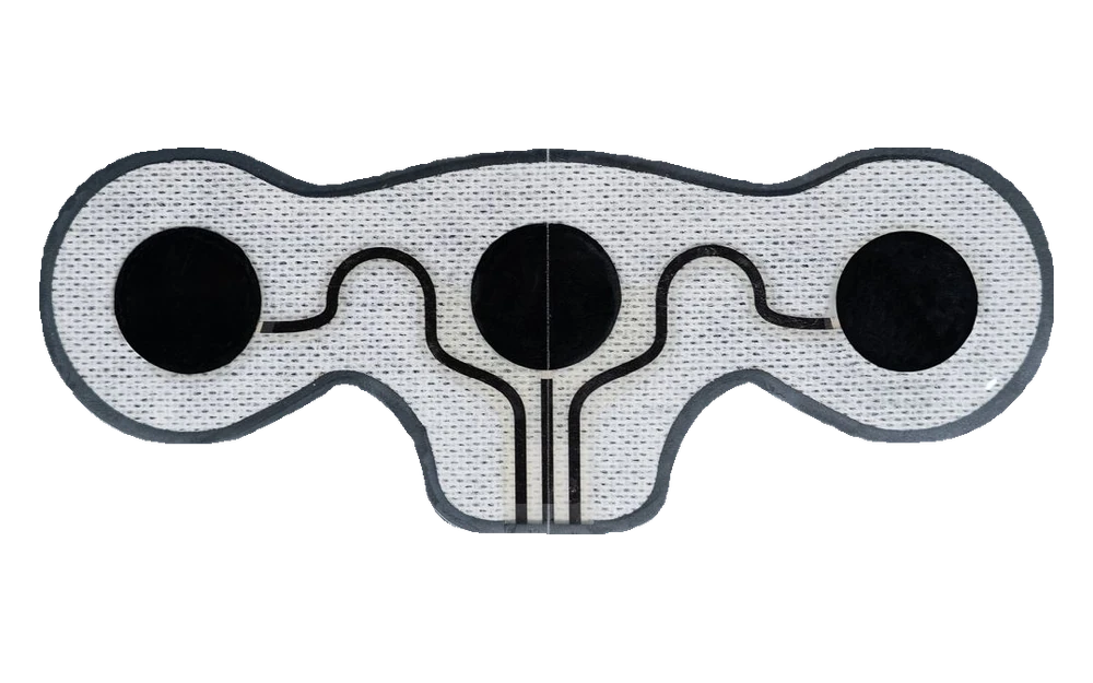
JASPER can manufacture custom bioimpedance and biopotential electrode-array components from controlled artwork and material specifications. Two-electrode, four-electrode, segmental, wearable, or research layouts can be reviewed without assuming that one arrangement fits every frequency, body site, movement condition, or algorithm. The OEM defines excitation, measurement range, safety limits, calibration, compensation, contact-quality detection, data processing, and intended interpretation.
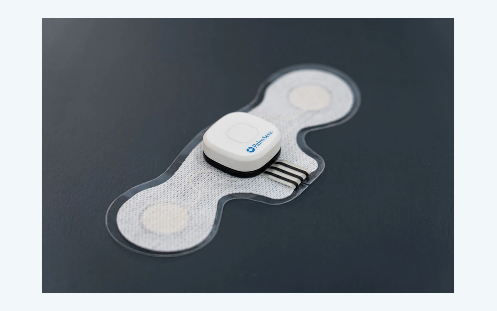
Placement and electronics should be reviewed before converting tooling fixes the electrode spacing, tail exit, adhesive footprint, and body-site geometry.
Define intended measurement, two- or four-electrode method, frequencies, current and sense channels, body site, placement, wear time, movement, electronics, cable, connector, calibration, safety, and regulatory owner.
Release electrode material and area, spacing, routing, dielectric, guards or shields, tail, connector pads, adhesive, spacer, liner, backing, outline, datums, skin-contact and packaging boundaries.
Build samples using proposed materials and process, inspect geometry, registration, continuity, isolation, route and connector, adhesive and conversion, then correlate with OEM impedance and contact-quality testing.
Maintain active files, materials, lots, process and inspection methods, approved samples, packaging, placement aids, traceability, deviations, and change notification linked to system validation.
Measured variation can originate in the patch, skin interface, placement, cable, electronics, environment, calibration, or algorithm. Acceptance criteria should identify the layer being tested.
| Variation source | Inputs and checks | Boundary to confirm |
|---|---|---|
| Electrode geometry | Area, spacing, shape, edge, channel identity, placement datum, registration and cut tolerance | Component drawing and body-site placement method |
| Printed circuit and interconnect | Ink, trace geometry, dielectric, shield or guard, tail, connector, continuity, isolation and resistance | Patch, cable, connector and electronics interface |
| Skin-contact stack | Electrode interface, gel if used, adhesive, spacer, liner, wear time, movement, moisture, pressure and removal | Final materials, biological safety and intended-use conditions |
| Measurement and interpretation | Frequency, excitation, instrument, calibration, contact detection, compensation, reference, algorithm and output claim | OEM system validation and legal-manufacturer responsibility |
A clear channel map and body-site drawing are as important as the outer patch shape.
JASPER can review two- and multi-electrode printed layouts with defined current and sense zones, spacing, routing, dielectric, tail, connector, adhesive, liner, body-site geometry, and inspection criteria.
No universal conclusion should be assumed. Electrode interface, area, spacing, routing, cable, connector, electronics, skin condition, placement, and algorithm can affect frequency-dependent behavior and must be validated for the intended system.
Project checks can include appearance, dimensions, registration, continuity, isolation, route or contact resistance, connector mapping, adhesive and conversion features, packaging, and other agreed methods. Frequency-dependent criteria require defined fixtures and conditions.
No. Accuracy depends on the complete measurement architecture, body site, placement, contact, excitation, electronics, calibration, population, environmental conditions, reference method, and algorithm owned by the OEM.
Send the channel map, patch stack, body-site and placement context, frequencies, electronics interface, quantities, and correlation criteria for review.
Share the project basics. JASPER will review the stack, materials, connector, quantity, and production risks.