
Home / Case Studies / Waterproof Outdoor Membrane Switch
Anonymous engineering case
Waterproof Outdoor Membrane Switch Designed Around the Complete Seal Path
A smooth overlay can shed water and the finished equipment can still leak. The real boundary runs through the printed face, laminated edges, windows, adhesive, tail exit, connector, gasket, housing joint, mounting surface and assembly process.
This page follows a representative outdoor control-panel project from exposure definition through sample and assembly review. It does not claim a customer, protection rating or field result.
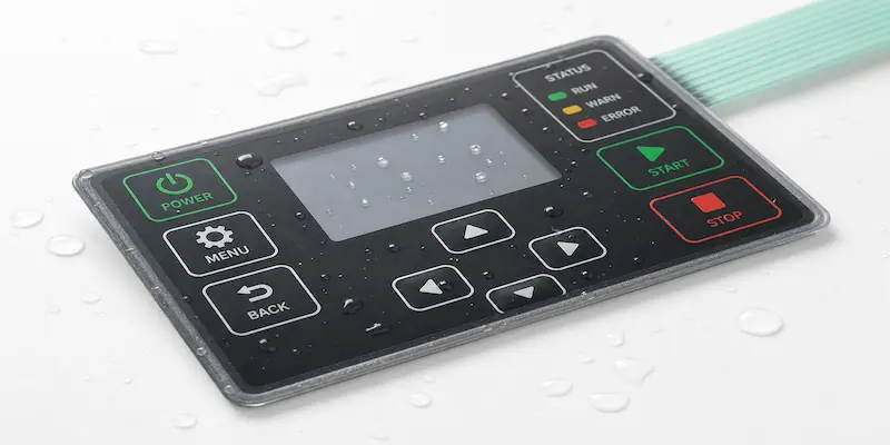
The protection result belongs to the evaluated assembly
A loose membrane switch does not establish the protection level of an equipment enclosure. The final result depends on the defined front surface, seal width, openings, tail and connector route, gasket or adhesive, enclosure geometry, assembly pressure, drainage, test method and production controls. This example describes the review process without publishing an unverified rating.
Project frame
The useful first question is how water reaches the interface, not which rating should appear on a drawing. These five inputs define the sealing review.
Start with the path water can take
Water rarely enters through the center of an intact overlay. It follows edges, narrow adhesive lands, window interfaces, cutouts, poorly supported corners, a folded tail, a cable entry or a housing seam. The design review should trace each path from the exposed side to the electronics.
The adhesive layer is both a bond and part of the boundary. Its performance changes with bond width, surface energy, texture, flatness, contamination, application pressure, dwell, temperature and the mechanical load created by the enclosure.
Condensation adds a different problem. Moisture may form inside a housing without crossing the front panel. Venting, drainage, cable routing, heat sources and cold surfaces therefore belong in the same discussion as the membrane switch.
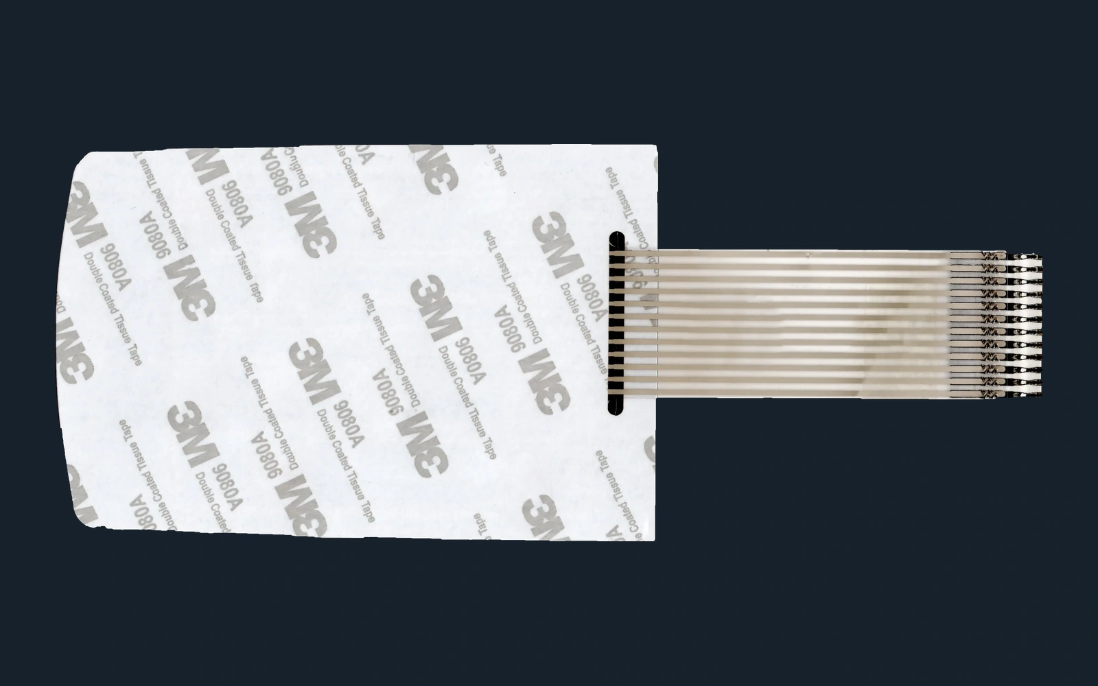
Six interfaces can interrupt one seal path
The page groups closely related front-surface decisions together, then follows the boundary through the five interfaces most likely to be overlooked.
Overlay, print and formed features
Film, reverse printing, texture, embossing and display areas must tolerate the stated exposure without creating cracks, lifting edges or hard-to-clean recesses.
Perimeter adhesive land
Seal width, corner shape, cutout clearance and pressure distribution matter as much as the adhesive family. A narrow or interrupted land creates a short route toward the circuit.
Windows and openings
Display windows, indicators, vents, fasteners and other penetrations need their own boundary. A clear front face does not protect an opening behind it.
Tail exit and connector route
The flexible tail crosses the panel edge and can channel water toward the housing. Exit geometry, bend, strain, connector location and cable entry must be reviewed together.
Enclosure and mounting surface
Flatness, texture, paint, molded ribs, recesses, seams, gasket compression and assembly access determine whether the released seal can actually be built.
Review the assembly through four exposure states
A single photograph taken after a water test says little about where moisture moved. The sample record should preserve the condition before, during and after exposure.
Dry reference
Record the assembled baseline before exposure
Inspect edge contact, adhesive wet-out, window and cutout boundaries, tail position, connector area, enclosure seams and the dry electrical state.
Directed exposure
Apply water from the directions the equipment will actually face
Use the agreed spray, splash, cleaning or pooling condition and observe upper edges, corners, recesses, openings and the tail route rather than treating the face as one uniform zone.
Temperature and moisture change
Separate external ingress from internal condensation
Review temperature transition, trapped humidity, venting and drainage in representative hardware. Moisture inside the enclosure does not automatically identify the front panel as the entry point.
Post-exposure
Inspect the boundary after the surface looks dry
Check electrical function, adhesive lift, edge whitening, water tracks, window fogging, connector moisture, corrosion evidence and any change in key feel or graphics.
The first assembly sample had to answer four sealing questions
These questions turn a general request for a waterproof membrane switch into an assembly that can be reviewed and improved.
Which component carries each part of the environmental boundary?
Mark the front film, adhesive perimeter, gasket, housing joint, connector opening and cable entry on the same section drawing. Unassigned gaps become visible before tooling.
Is there enough stable bonding area around every corner and opening?
Review land width, radius, recess depth, molded texture, coating, flatness and assembly access. The drawing should show where pressure is applied and where the bond can be inspected.
How does the circuit tail leave the sealed zone?
Define exit direction, slot or channel, bend support, strain relief, connector position and any secondary cable seal. Avoid creating a downhill route toward the electronics.
Where does water go if it reaches a recess or the inside of the housing?
Provide drainage, venting or isolation where the equipment needs it. A membrane switch should not be expected to correct an enclosure that traps water against its edge.
What the buyer should approve during sampling
The approved sample should include the real mounting surface and a written exposure method. Testing a loose panel on a flat laboratory plate leaves the most important interfaces unexamined.
Inspect the panel, adhesive and enclosure before assembly
Confirm artwork revision, perimeter geometry, openings, liner condition, bonding surface, cleanliness, flatness, texture, gasket and tail route.
Assemble with the intended process and support
Use the planned fixture, pressure sequence, dwell, fasteners, gasket compression, cable routing and connector installation. Record any area that cannot be pressed or inspected.
Run the agreed exposure on representative hardware
Apply water and temperature conditions from defined directions while monitoring the intended electrical state and the interfaces most likely to collect moisture.
Release a controlled assembly reference
Link the accepted panel, adhesive, enclosure revision, surface preparation, assembly work instruction, exposure method and post-test inspection record.
Production controls that protect the approved boundary
Sealing depends on repeatable cut geometry, clean lamination, correct adhesive handling, controlled tail features and traceable electrical inspection. A visually small defect can create a direct path toward the circuit.

Material and lamination control
Edges, openings and adhesive surfaces need deliberate visual inspection
Printing, die cutting, adhesive conversion and lamination should preserve the released perimeter and keep contamination, wrinkles, trapped particles and liner damage away from the bonding path.
- Overlay, spacer and adhesive revisions matched before lamination
- Perimeter, window, cutout and tail geometry checked against the released drawing
- Bonding surfaces and liners protected from particles, fingerprints and damage

Circuit and tail control
Electrical testing does not replace inspection of the exit path
Continuity and switch checks confirm the circuit. Tail position, conductor coverage, connector termination, reinforcement, bend condition and edge relationship still need separate acceptance criteria.
- Open, short, continuity and switch function checked to the released circuit
- Tail exit, reinforcement, connector and strain area inspected by revision
- Panel, test record and assembly reference kept under the same identification
What to send before the seal path is fixed
An enclosure section and an honest exposure description are more useful than a rating request with no hardware context.
Water source, direction, duration, frequency, cleaning method, pooling, dust, sunlight, temperature change and condensation concerns
Section drawing, mounting ledge, recess, surface material, coating, texture, flatness, seams, fasteners, gasket and drainage features
Outline, corners, windows, key embossing, openings, keep-outs, target thickness, edge clearances and available adhesive land
Exit direction, bend zone, slot or channel, reinforcement, cable route, connector position, strain relief and enclosure entry
Cleaning method, fixture, applied pressure, sequence, dwell, gasket compression, fastener torque controls and inspection access
Representative hardware, exposure method, electrical monitoring, moisture-detection approach, post-test checks and required documentation
Continue the review with the underlying technical pages
These pages cover the product, adhesive, sealing and engineering decisions behind an outdoor membrane switch assembly.
Questions that usually come up before a similar RFQ
Can JASPER manufacture waterproof membrane switches for outdoor equipment?
JASPER can manufacture custom membrane switches for outdoor and wet environments when the exposure, panel construction, adhesive, openings, tail route, enclosure and validation method are defined. The finished equipment still requires project-specific assembly testing.
Does a waterproof membrane switch give the enclosure a protection rating?
Not by itself. A protection result belongs to the evaluated enclosure assembly, including the panel bond, gasket, seams, openings, connector or cable entries, assembly process and test configuration.
Where do outdoor membrane switch assemblies most often need extra review?
Common review points are narrow perimeter bonds, sharp corners, display windows, cutouts, tail exits, connector openings, textured or contaminated mounting surfaces, unsupported edges, housing seams and locations where water can pool.
How should the flexible tail be handled in a sealed design?
Define the exit direction, bend support, reinforcement, slot or channel, strain relief, connector location and any secondary cable seal. The tail should not create an uncontrolled path from the exposed edge to the electronics.
What is the minimum information needed for a first sealing review?
Send the panel and enclosure drawings, the exposure and cleaning conditions, mounting-surface details, windows and openings, tail and connector route, assembly method and the evidence required after sample testing.
Design the boundary before asking the sample to prove it
Send the exposure profile, panel artwork, enclosure section, mounting surface, openings, tail and connector route, assembly process and approval method. JASPER can review the open seal-path decisions before they become tooling or equipment-level test changes.