
Intended system definition
Identify intended treatment or research use, active and return function, formulation owner, current controller, body site, contact duration, environment, user, packaging, shelf life, standards, and legal manufacturer.
Iontophoresis patches combine an electrical path, active and return electrode zones, reservoir or interface media, skin-contact materials, packaging, electronics, and often a drug-device or treatment-specific regulatory strategy. JASPER supports only the quoted printed and converted component boundary against OEM-controlled artwork and specifications.
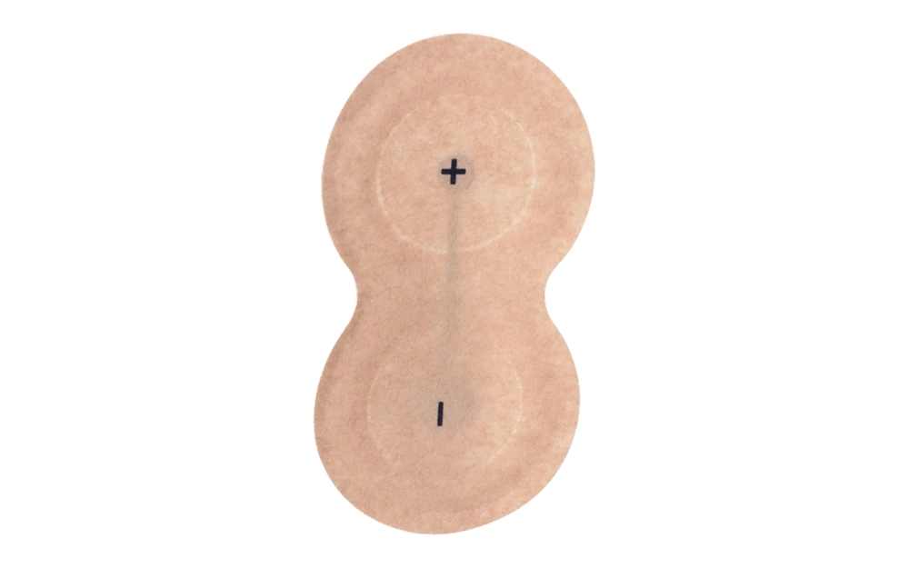
JASPER can print and convert electrode patch platforms with defined active and return zones, conductors, dielectric, spacers, adhesive patterns, liners, tails, and connectors. The OEM or legal manufacturer controls formulation, polarity, current profile, dose, reservoir loading, release kinetics, controller, risk management, biological safety, packaging, shelf life, use instructions, and finished-device or combination-product validation.
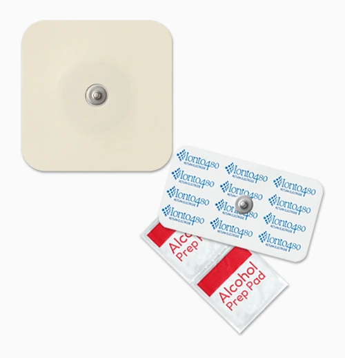
The most serious errors occur when a manufacturing drawing hides formulation, electrical, skin-contact, or packaging assumptions that belong to another owner.
Identify intended treatment or research use, active and return function, formulation owner, current controller, body site, contact duration, environment, user, packaging, shelf life, standards, and legal manufacturer.
Release conductor and dielectric artwork, materials, electrode areas, spacer or reservoir geometry, adhesive, backing, liner, tail, connector, polarity marking, outline, datums, filling and sealing boundaries.
Build the quoted dry or loaded component stage, inspect dimensions, registration, circuit, connector, reservoir and adhesive geometry, assembly and packaging fit, then correlate with OEM current and delivery studies.
Maintain active files, material and lot identity, process and inspection records, loading or downstream handoff, packaging, storage, approved references, deviations, and change notification.
The same physical patch can behave differently with another formulation, controller, skin site, loading process, storage condition, or use duration.
| System area | Inputs to define | Evidence owner |
|---|---|---|
| Printed electrode component | Ink and substrate, polarity, area, spacing, routing, dielectric, tail, connector, resistance, geometry and conversion | JASPER within quoted manufacturing checks |
| Reservoir and formulation | Drug or active material, vehicle, gel, membrane, loading, uniformity, compatibility, release and stability | OEM/formulation and combination-product owner |
| Controller and energy | Current profile, voltage compliance, monitoring, fault handling, contact detection, timing, cable and connector | OEM electrical and software validation |
| Skin use and final product | Body site, duration, dose, adhesion, irritation, heating, packaging, shelf life, usability, labeling and clinical claim | Legal manufacturer and finished-product validation |
Confidential formulation details can remain controlled, but the manufacturing boundary and interfaces must be clear enough to prevent an unsafe assumption.
JASPER can review multi-zone printed and converted artwork with defined materials, polarity, spacing, routing, dielectric, spacer, adhesive, tail, connector, and downstream reservoir or loading boundary.
Component geometry and circuit checks can be performed, but delivery, heating, fault response, current distribution, dose, and treatment performance require the intended controller, loaded patch, placement, and use conditions.
Provide the zone artwork, stack, materials, reservoir and adhesive boundaries, tail and connector, electrical envelope, body-contact context, downstream loading, packaging, quantities, standards, and validation ownership.
Send the electrode and reservoir artwork, material stack, controller interface, contact conditions, downstream operations, quantities, and validation ownership for review.
Share the project basics. JASPER will review the stack, materials, connector, quantity, and production risks.