PCB and FPC Membrane Switch Assemblies
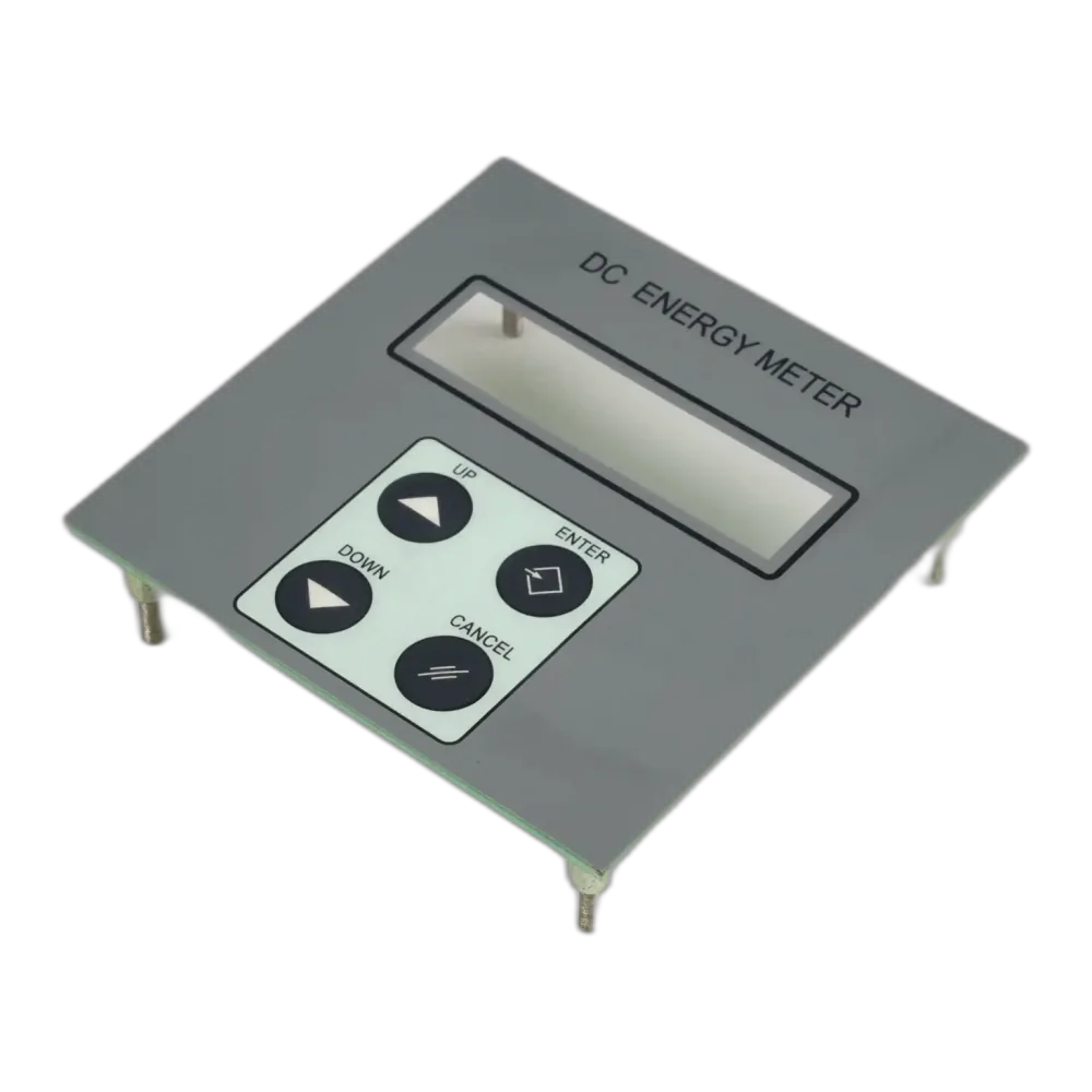
PCB and FPC membrane switch assemblies are used when a simple printed silver circuit is not enough. They can support components, tighter connector requirements, LEDs, shielding, or a more controlled electrical interface.
- switch panels with LEDs or mounted components
- assemblies needing stronger connector retention
- interfaces with tight routing or EMI constraints
- control panels supplied as tested electrical subassemblies
Engineering reference
When this product fits
PCB and FPC membrane switch assemblies are used when a simple printed silver circuit is not enough. They can support components, tighter connector requirements, LEDs, shielding, or a more controlled electrical interface.
- switch panels with LEDs or mounted components
- assemblies needing stronger connector retention
- interfaces with tight routing or EMI constraints
- control panels supplied as tested electrical subassemblies
Engineering reference
Engineering notes before tooling
Choose PCB when component mounting or rigidity helps. Choose FPC when bending and compact routing matter.
Connector orientation should be checked in the installed position, not only on a flat drawing.
Printed silver circuits remain cost-effective for many simple key matrices.
Continuity testing should include tail and connector handling, not only the key matrix.
Engineering reference
Common failure points
connector height conflicts with housing depth
bend radius too tight at FPC exit
LED polarity not aligned with the harness
test pads missing from the final layout
Engineering reference
What to send for RFQ
Engineering reference
Related design guidance
FAQ
Questions buyers usually ask
What affects the cost of PCB and FPC membrane switch assemblies?
Main drivers include material, printed colors, tooling, dome or LED count, connector, adhesive stack, test requirement, and order quantity.
What should be tested at sample stage?
Check continuity, appearance, actuation feel, tail bend, adhesive fit, window clarity, LED visibility, and any IP or cleaning requirement in the real enclosure.
When is this design not recommended?
It is not recommended when the required travel, current load, serviceability, temperature, or mechanical abuse exceeds what a thin interface stack can handle.
RFQ support
Send a drawing before the design is locked.
For PCB and FPC membrane switch assemblies, the useful review happens before tail exit, connector, adhesive, and artwork decisions become expensive to change.